1999 DODGE NEON fuse box
[x] Cancel search: fuse boxPage 526 of 1200

BATT A0
POWER
DISTRIBUTION
CENTER
13 14
10A
FUSE
13 2FUSE
15A
2
22
BATT A3
BLOCK FUSE
299
4A
FUSE
9
14
F33
20
PK/RDE1
20
TN
13C103
M1
18
PK
M1
22
PK
2
1
GLOVE
BOX
LAMP
AND
SWITCH
Z3
20
BK/OR
S203
M1
22
PK
BK/OR20 Z3
LAMP PRNDL
E2
22
OR
1
2
Z3
20
BK/OR
E2
20
OR
Z3
14
BK/OR
G204
LAMP RECEIVER
ASH S210
S201
2
1 0
LAMPS READING
MAP/
B
Z3
18
BK/OR
Z3
20
BK/OR
3C225
M2
22
YL
M23
18
YL/BK
2C225
M1
22
PK
E2
22
OR
2
1M1
18
PK
M1
18
PK
1C225
S309
CA
2 HEAD 1 PARK
0 OFF
HEADLAMP
SWITCH
TO
S224
(8W-10-6)
(8W-10-13) (8W-11-9)(8W-11-4)
(8W-11-19)
(8W-10-13)
(8W-15-11)(8W-11-19)
(8W-15-11) (8W-10-8) (8W-10-6)
(8W-10-13)(8W-50-4)
(8W-44-6)
PL8W-44 INTERIOR LIGHTING
RHD8W - 44 - 5
8295J988W-1
Page 527 of 1200

SWITCH AJAR
DOOR
FRONT
LEFT RIGHT
FRONT
DOOR
AJAR
SWITCH
LEFT
REAR
DOOR
AJAR
SWITCH
SWITCH AJAR
DOOR
REAR
RIGHT
S304
13FUSE10A
BATT A0
M1
18
PK
M2
20
YLM2
20
YLM2
20
YLM2
20
YL
M1
20
PK
M1
22
PK
13C103
3C105
21
M1
22
PK
1
3
M2
20
YL
M4
18
GY/BK
TRUNK
SWITCH
S224
M2
20
YL
3
SWITCH HEADLAMP
M2
20
YL
Z1
20
BK
Z1
20
BK
S202
G204
2
AND LAMP
BOX
GLOVE
M1
22
PK
M1
22
PK
S203
DOME
LAMP LAMP TRUNK
M2
20
YL
16C230
CENTER DISTRIBUTION
POWER
13 14
SWITCH
A
M23
18
YL/BK
M2
22
YL
MAP/
READING
LAMPS
2C225
GY/BK22 M4
PK22 M2
1
IMMOBILIZER
3C309
1C242
M23
20
YL/BK
(8W-10-13)(8W-10-6)
(8W-50-4)
(8W-15-11)
(8W-15-11) (8W-10-13)(8W-10-6)
(8W-44-5)(8W-44-5)
(8W-61-8)
8W - 44 - 6 8W-44 INTERIOR LIGHTING
RHDPL
J988W-18296
Page 629 of 1200

CAV CIRCUIT FUNCTION
1 K13 18YL/WT FUEL INJECTOR NO. 3 DRIVER
2 A142 18DG/OR AUTOMATIC SHUT DOWN RELAY OUTPUT
CAV CIRCUIT FUNCTION
1 K14 18LB/BR
2 A142 18DG/OR AUTOMATIC SHUT DOWN RELAY OUTPUT
CAV CIRCUIT FUNCTION
1 Z1 18BK GROUND
2 Z2 18BK GROUND
3 G4 18DB FUEL LEVEL SENSOR SIGNAL
4 A141 18DG/WT FUEL PUMP RELAY OUTPUT
LT GRAY
4
1
BLACK
CAV CIRCUIT FUNCTION
1
A142 18DG/OR AUTOMATIC SHUT DOWN RELAY OUTPUT 2K20 18DG GENERATOR FIELD DRIVER 2
1
CAV CIRCUIT FUNCTION
1
M1 22PK FUSED B(+) 2Z3 20BK/OR GROUND
1 2GRAY (LHD)
BLACK
12
BLACK
12
FUEL
INJECTOR NO. 3
INJECTOR NO. 4FUEL
FUEL PUMP
MODULE
GENERATOR
BLACK (RHD)
AND SWITCH GLOVE BOX LAMP
FUEL INJECTOR NO. 4 DRIVER
8W - 80 - 20 8W-80 CONNECTOR PIN-OUTSPL
J988W-1PL008020
Page 655 of 1200

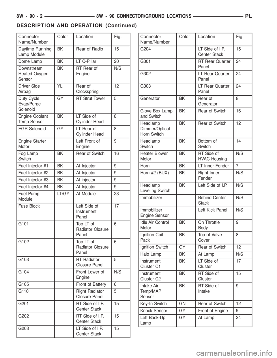
Connector
Name/NumberColor Location Fig.
Daytime Running
Lamp ModuleBK Rear of Radio 15
Dome Lamp BK LT C-Pillar 20
Downstream
Heated Oxygen
SensorBK RT Rear of
EngineN/S
Driver Side
AirbagYL Rear of
Clockspring12
Duty Cycle
Evap/Purge
SolenoidGY RT Strut Tower 5
Engine Coolant
Temp SensorBK LT Side of
Cylinder Head8
EGR Solenoid GY LT Rear of
Cylinder Head8
Engine Starter
MotorLeft Front of
Engine9
Fog Lamp
SwitchBK Rear of Switch 16
Fuel Injector #1 BK At Injector 9
Fuel Injector #2 BK At Injector 9
Fuel Injector #3 BK At injector 9
Fuel Injector #4 BK At Injector 9
Fuel Pump
ModuleLT/GY At Module 23
Fuse Block Left Side of
Instrument
Panel17
G101 Top LT of
Radiator Closure
Panel6
G102 Top LT of
Radiator Closure
Panel6
G103 RT Radiator
Closure Panel5
G104 Front Lower of
EngineN/S
G105 Front of Battery 6
G110 Right Radiator
Closure Panel5
G201 RT Side of I.P.
Center Stack15
G202 RT Side of I.P.
Center Stack15
G203 LT Side of I.P.
Center Stack15
Connector
Name/NumberColor Location Fig.
G204 LT Side of I.P.
Center Stack15
G301 RT Rear Quarter
Panel24
G302 LT Rear Quarter
Panel24
G303 LT Rear Quarter
Panel24
Generator BK Rear of
Generator8
Glove Box Lamp
and SwitchBK Rear of Switch 16
Headlamp
Dimmer/Optical
Horn SwitchBK Rear of Switch 12
Headlamp
SwitchBK Bottom of
Switch14
Heater Blower
MotorBK RT Side of
HVAC HousingN/S
Horn BK LT Inner Fender 7
Horn #2 (BUX) BK Right Inner
FenderN/S
Headlamp
Leveling SwitchBK Left Side of I.P. N/S
Immobilizer Behind Center
StackN/S
Immobilizer
Engine SensorLeft Kick Panel N/S
Idle Air Control
MotorBK On Throttle
Body9
Ignition Coil
PackBK Top of Valve
Cover8
Ignition Switch GY Rear of Switch 12
Halo Lamp BK At Lamp N/S
Instrument
Cluster C1BK LT Side of
Cluster17
Instrument
Cluster C2BK RT Side of
Cluster15
Intake Air
Temp/MAP
SensorBK RT Side of
Intake9
Key-In Switch GN Rear of Switch 12
Knock Sensor GY Front of Engine 9
Left Back-Up
LampGY At Lamp 24
8W - 90 - 2 8W - 90 CONNECTOR/GROUND LOCATIONSPL
DESCRIPTION AND OPERATION (Continued)
Page 677 of 1200

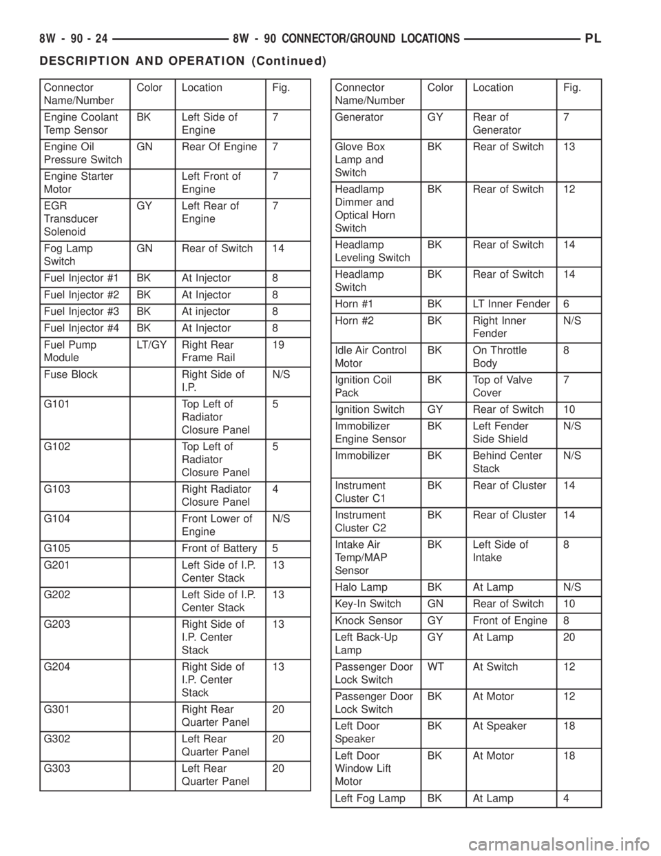
Connector
Name/NumberColor Location Fig.
Engine Coolant
Temp SensorBK Left Side of
Engine7
Engine Oil
Pressure SwitchGN Rear Of Engine 7
Engine Starter
MotorLeft Front of
Engine7
EGR
Transducer
SolenoidGY Left Rear of
Engine7
Fog Lamp
SwitchGN Rear of Switch 14
Fuel Injector #1 BK At Injector 8
Fuel Injector #2 BK At Injector 8
Fuel Injector #3 BK At injector 8
Fuel Injector #4 BK At Injector 8
Fuel Pump
ModuleLT/GY Right Rear
Frame Rail19
Fuse Block Right Side of
I.P.N/S
G101 Top Left of
Radiator
Closure Panel5
G102 Top Left of
Radiator
Closure Panel5
G103 Right Radiator
Closure Panel4
G104 Front Lower of
EngineN/S
G105 Front of Battery 5
G201 Left Side of I.P.
Center Stack13
G202 Left Side of I.P.
Center Stack13
G203 Right Side of
I.P. Center
Stack13
G204 Right Side of
I.P. Center
Stack13
G301 Right Rear
Quarter Panel20
G302 Left Rear
Quarter Panel20
G303 Left Rear
Quarter Panel20Connector
Name/NumberColor Location Fig.
Generator GY Rear of
Generator7
Glove Box
Lamp and
SwitchBK Rear of Switch 13
Headlamp
Dimmer and
Optical Horn
SwitchBK Rear of Switch 12
Headlamp
Leveling SwitchBK Rear of Switch 14
Headlamp
SwitchBK Rear of Switch 14
Horn #1 BK LT Inner Fender 6
Horn #2 BK Right Inner
FenderN/S
Idle Air Control
MotorBK On Throttle
Body8
Ignition Coil
PackBK Top of Valve
Cover7
Ignition Switch GY Rear of Switch 10
Immobilizer
Engine SensorBK Left Fender
Side ShieldN/S
Immobilizer BK Behind Center
StackN/S
Instrument
Cluster C1BK Rear of Cluster 14
Instrument
Cluster C2BK Rear of Cluster 14
Intake Air
Temp/MAP
SensorBK Left Side of
Intake8
Halo Lamp BK At Lamp N/S
Key-In Switch GN Rear of Switch 10
Knock Sensor GY Front of Engine 8
Left Back-Up
LampGY At Lamp 20
Passenger Door
Lock SwitchWT At Switch 12
Passenger Door
Lock SwitchBK At Motor 12
Left Door
SpeakerBK At Speaker 18
Left Door
Window Lift
MotorBK At Motor 18
Left Fog Lamp BK At Lamp 4
8W - 90 - 24 8W - 90 CONNECTOR/GROUND LOCATIONSPL
DESCRIPTION AND OPERATION (Continued)
Page 1141 of 1200

(3) Close all doors, windows and vents to the pas-
senger compartment.
(4) Set Heater-A/C control to A/C, full heat, floor,
RECIRC. and high blower.
(5) Start the engine and hold the idle speed (1000
rpm). After the engine has reached running temper-
ature, allow the passenger compartment to heat up.
This will create the need for maximum refrigerant
flow into the evaporator.
(6) If the refrigerant charge is sufficient, discharge
(high pressure) gauge should read 965 to 2620 kPa
(140 to 380 psi). Suction (low pressure) gauge should
read 103 to 2417 kPa (15 to 35 psi). If system cannot
achieve proper pressure readings, replace the expan-
sion valve. If pressure is correct, proceed with test.
WARNING: PROTECT SKIN AND EYES FROM CON-
TACTING CO2 PERSONAL INJURY CAN RESULT.
(7) If suction side low pressure is within specified
range, freeze the expansion valve control head (Fig.
10) for 30 seconds. Use a super cold substance (liquid
CO2).Do not spray refrigerant on the expansion
valve for this test.Suction side low pressure should
drop to 34.5 kPa (5 psi) If not, replace expansion
valve.
(8) Allow expansion valve to thaw. The low pres-
sure gauge reading should stabilize at 103 to 241
kPa (15 to 35 psi). If not, replace expansion valve.
(9) When expansion valve test is complete, test
A/C overall performance. Refer to the Heater and A/C
Performance Test in this section. Remove all test
equipment before returning vehicle to use.
BLOWER MOTOR ELECTRICAL DIAGNOSIS
Refer to the Blower Motor Electrical System Diag-
nosis chart in this section. Also refer to Group 8W,
Wiring Diagrams for more information.
BLOWER MOTOR VIBRATION AND/OR NOISE
DIAGNOSIS
The resistor block supplies the blower motor with
varied voltage (low and middle speeds) or battery
voltage (high speed).
CAUTION: Stay clear of the blower motor and resis-
tor block (Hot). Do not operate the blower motor
with the resistor block removed from the heater-A/C
housing.
Refer to the Blower Motor Vibration/Noise chart
for diagnosis.
EVAPORATOR PROBE TEST
The work area and vehicle must be between 16É C
(60É F) and 32É C (90É F) when testing the switch.(1) Disconnect the three wire connector from the
evaporator probe lead located behind the glove box.
(2) Start engine and set A/C to low blower motor
speed, panel, full cool, and RECIRC.
(3) Using a voltmeter, check for battery voltage
between Pin 1 and 2. If no voltage is detected, there
is no power to the switch. Check wiring and fuses.
Refer to Group 8W, Wiring Diagrams for circuit diag-
nosis.
(4) Using a voltmeter, check for battery voltage
between Pin 1 and Pin 3. If no voltage is detected,
there is no voltage from the Powertrain Control Mod-
ule. Refer to Group 8W, Wiring Diagrams. If voltage
is OK, connect a jumper wire between Pin 1 and Pin
3. The compressor clutch should engage. If the clutch
engages, remove the jumper wire immediately and go
to Step 5. If the compressor clutch does not engage,
check the operation of the clutch and repair as nec-
essary.
(5) If compressor clutch engages, connect the evap-
orator probe 3-way connector. The compressor clutch
should engage or cycle depending on evaporator tem-
perature. If OK, go to Step 6. If not OK, replace the
clutch cycling switch.
(6) The engine running and the A/C set to:
²Blower motor on low speed
²Panel position
²Full cool
²RECIRC.
Close all doors and windows. Place a thermometer
in the center discharge vent.
(7) If the clutch does not begin to cycle off between
2É C to 7É C (35É F to 45É F), verify that the evapo-
rator probe is fully installed and not loose in evapo-
rator. If it is not properly installed, install probe and
retest outlet temperature. If the evaporator probe is
properly installed, replace the clutch cycling switch.
HEATER PERFORMANCE TEST
PRE-DIAGNOSTIC PREPARATIONS
Review Safety Precautions and Warnings in this
group before performing the following procedures.
Check the coolant level, drive belt tension, vacuum
line connections, radiator air flow and fan operation.
Start engine and allow to warm up to normal tem-
perature.
WARNING: DO NOT REMOVE RADIATOR CAP
WHEN ENGINE IS HOT, PERSONAL INJURY CAN
RESULT.
If vehicle has been run recently, wait 15 minutes
before removing cap. Place a rag over the cap and
turn it to the first safety stop. Allow pressure to
escape through the overflow tube. When the system
stabilizes, remove the cap completely.
24 - 8 HEATING AND AIR CONDITIONINGPL
DIAGNOSIS AND TESTING (Continued)