Page 17 of 51
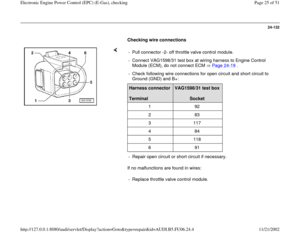
24-125
Display fields
1 2 3 4
Display group 060: Adaptation of throttle valve control module
Display xx % xx %
x
---
Indicated Throttle
valve angle
(angle
sensor 1) Throttle
valve angle
(angle
sensor 2) Adaptation step counter
Adaptation condition
Functional
range
0 to 8
ADP in progress
ADP OK
ERROR
Specified
value 3 to 93 % 97 to 3 %
8
ADP OK
Note
After adaptation, the adaptation step
counter reaches the number 8 (it is OK for
numbers to be skipped). If "ERROR." is displayed:
Check DTC memory Page
01
-16
.
If specified value is not
obtained: Note, Page 24
-
126
Note:
The abbreviation "ADP" in display field 4 stands for "Adaptation".
Pa
ge 17 of 51 Electronic En
gine Power Control
(EPC
) (E-Gas
), checkin
g
11/21/2002 htt
p://127.0.0.1:8080/audi/servlet/Dis
play?action=Goto&t
yp
e=re
pair&id=AUDI.B5.FU06.24.4
Page 18 of 51
24-126
Note:
The control module can abort adaptation for the
following reasons:
Throttle valve cannot be closed completely (e.g.
contamination).
Battery voltage is too low.
Throttle valve control module or wire connection
is faulty.
Engine is started during adaptation or
accelerator pedal is operated.
Tension of throttle valve housing (check
bolts).
After termination, tester displays "Function is
unknown or cannot be performed at the
moment". The next time the ignition is switched
on (several seconds), adaptation will be
automatically repeated.
- End basic adjustment of the engine by pressing
the key.
Rapid data transfer
HELP
Indicated on display (function selection):
Pa
ge 18 of 51 Electronic En
gine Power Control
(EPC
) (E-Gas
), checkin
g
11/21/2002 htt
p://127.0.0.1:8080/audi/servlet/Dis
play?action=Goto&t
yp
e=re
pair&id=AUDI.B5.FU06.24.4
Page 19 of 51
Select function XX
Pa
ge 19 of 51 Electronic En
gine Power Control
(EPC
) (E-Gas
), checkin
g
11/21/2002 htt
p://127.0.0.1:8080/audi/servlet/Dis
play?action=Goto&t
yp
e=re
pair&id=AUDI.B5.FU06.24.4
Page 20 of 51
24-127
Angle sensor -1- for throttle drive,
checking
Special tools and equipment
VAG1526A
VAG1594A
VAG1598/31
VAS5051 with VAG5051/1
- or
VAG1551 with VAG1551/3A
Pa
ge 20 of 51 Electronic En
gine Power Control
(EPC
) (E-Gas
), checkin
g
11/21/2002 htt
p://127.0.0.1:8080/audi/servlet/Dis
play?action=Goto&t
yp
e=re
pair&id=AUDI.B5.FU06.24.4
Page 21 of 51
 -G187- and angle sensor 1
for throttle drive (power accelerator actuation) -
G188- inform the Engine Control Module (ECM")
24-128
Angle sensor 1 for throttle drive (power
accelerator actuation) -G187- and angle sensor 1
for throttle drive (power accelerator actuation) -
G188- inform the Engine Control Module (ECM)
about the position of the throttle valve. Both
angle sensors are located in the throttle valve
control module.
Test sequence
- Connect VAS5051 tester or VAG1551 scan tool
and select control module for engine electronics
using "address word" 01 Page 01
-10
. Ignition
must remain switched on.
Rapid data transfer
HELP
Select function XX
When indicated on display
- Press buttons -0- and -8- to select "Read Measuring Value Block" and
press -Q- button to confirm input.
Read measuring value block
Q
Enter displa
y group number XXX
When indicated on display
- Press buttons -0-, -6- and -2- to select "display group number 062" and
press -Q- button to confirm input.
Read Measuring Value Block 62
1
2
3
4
Indicated on display
- Check specified values for E-gas potentiometer voltages in display
fields 1 and 2.
Pa
ge 21 of 51 Electronic En
gine Power Control
(EPC
) (E-Gas
), checkin
g
11/21/2002 htt
p://127.0.0.1:8080/audi/servlet/Dis
play?action=Goto&t
yp
e=re
pair&id=AUDI.B5.FU06.24.4
Page 22 of 51
 Throttle va")
24-129
Display fields
1 2 3 4
Display group 062: E-Gas potentiometer voltages
Display
xx %
xx % xx % xx %
Indicated
Throttle valve angle
(angle sensor 1) Throttle valve angle
(angle sensor 2) Sensor 1 for
Pedal position Sensor 2 for
Pedal position
Specified value
3 to 93 %
97 to 3 % 12 to 97 % 4 to 49 %
Note:
Engine Control Module (ECM) calculates the
voltage values of the angle sensors in percent
relative to 5 volts and displays these percentage
values. (5 volts supply voltage represents 100
%).
- Observe display field 1 and 2.
- Slowly depress accelerator pedal completely.
Percent indication in display field 1 must rise
uniformly. In the process, the tolerance range of
3 to 93% is not completely utilized.
Percent indication in display field 2 must
decrease uniformly. The tolerance range 97 to 3
% is not used completely during this.
Pa
ge 22 of 51 Electronic En
gine Power Control
(EPC
) (E-Gas
), checkin
g
11/21/2002 htt
p://127.0.0.1:8080/audi/servlet/Dis
play?action=Goto&t
yp
e=re
pair&id=AUDI.B5.FU06.24.4
Page 23 of 51

24-130
Note:
The reason why the value indicated in display
field 1 climbs, while the value indicated in
display field 2 decreases, has to do with the fact
that the potentiometers (angle sensors) in the
throttle valve control unit run in opposite
directions.
This means that the voltage tap of angle sensor
1 runs from 0 to 5 volts. (The more the throttle
valve is opened, the larger the voltage; percent
indication climbs).
The voltage tap of angle sensor 2 runs from 5
to 0 volts. (The more the throttle valve is
opened, the lower the voltage; the percentage
decreases).
If indications do not resemble description:
- Check voltage supply and wire connections of
throttle valve control module Page 24
-131
.
Pay particular attention to harness connectors
that could be loose or corroded.
- Check accelerator pedal position sensor Page
24
-133
.
Pa
ge 23 of 51 Electronic En
gine Power Control
(EPC
) (E-Gas
), checkin
g
11/21/2002 htt
p://127.0.0.1:8080/audi/servlet/Dis
play?action=Goto&t
yp
e=re
pair&id=AUDI.B5.FU06.24.4
Page 24 of 51
24-131
Check voltage supply throttle valve control
module
- Pull connector -2- off throttle valve control
module.
- Switch ignition on.
If specified values are not obtained: - Connect multimeter for voltage measurement as follows:Harness connector
Terminal
Specified value
2 + Ground (GND) about 5 V
2 + 6 about 5 V
- Check wire connections from Engine Control Module (ECM) to throttle
valve control module Page 24
-132
.
Pa
ge 24 of 51 Electronic En
gine Power Control
(EPC
) (E-Gas
), checkin
g
11/21/2002 htt
p://127.0.0.1:8080/audi/servlet/Dis
play?action=Goto&t
yp
e=re
pair&id=AUDI.B5.FU06.24.4


")
.
Battery voltage is too low")
 (E-Gas
), checkin
g
11/21/2002 htt
p://127.0.0.1:8080/audi/servlet/Dis
play?action=Goto&t
yp
e=re
pair&id=AUDI.B5.FU06.24.4")

