Page 3 of 64

3
Contents
Principles
Vehicle suspension.................................................................. 4
The suspension system .......................................................... 6
Vibration ................................................................................... 8
Characteristic values of springs .......................................... 12
Conventional running gear without self-levelling ............ 14
The self-study programme is not intended as a workshop manual.
The self-study programme will provide you with
information on design and functions.
New
NoteImportant:
Note
Page
For maintenance and repairs please refer to the current
technical literature.
Principles of air suspension
Self-levelling air suspension ............................................... 16
Characteristic values of air spring ...................................... 21
Vibration damping................................................................. 23
Shock absorbers (vibration dampers) ................................ 25
PDC shock absorbers ........................................................... 33
System overview ................................................................... 38
Air springs .............................................................................. 40
Air supply unit ........................................................................ 42
Diagram of pneumatic system ............................................. 43
Compressor ........................................................................... 44
Air dryer ................................................................................. 47
Discharge valve N111 ........................................................... 48
Valve for suspension struts N150 and N151....................... 51
Self-levelling suspension sender G84 ................................ 52
Self-levelling suspension control unit J197 ....................... 54
Self-levelling suspension warning lamps K134 ................ 55
Function diagram ................................................................... 56
Interfaces................................................................................ 57
The control concept .............................................................. 58
Other features of the control concept ................................ 60
Self-levelling suspension, A6
Page 4 of 64
4
Vehicle suspension
When a vehicle travels over irregular road
surfaces, impact forces are transmitted to the
wheels. These forces pass to the bodywork
via the suspension system and the wheel
suspension.
The purpose of the vehicle suspension is to
absorb and reduce these forces.
Principles
Wheel contact with the road surface, which
is essential for braking and steering, is
maintained.
The vehicle components are protected
against excessive stresses. Unpleasant and unhealthy stresses to vehicle
passengers are minimised, and damage to
fragile loads is avoided.
242_003
Driving safety
Operating safety
Driving comfort
When we talk about the vehicle suspension
we can basically distinguish between the
suspension system
and the
vibration
damping system
.
By means of the interaction of the two
systems, the following is achieved:
Page 10 of 64

10
The degree of damping of the vibration
damper has no signiÞcant inßuence on the
value of the natural frequency of the
bodywork. It inßuences only how quickly the
vibrations cease (damping coefÞcient). For
further information, see chapter ÒVibration
dampingÓ.
Matching of the natural frequency of the
bodywork
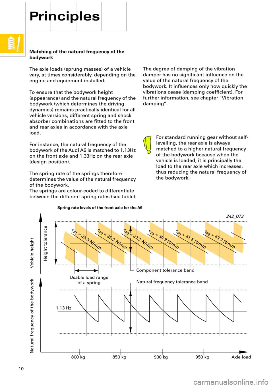
The axle loads (sprung masses) of a vehicle
vary, at times considerably, depending on the
engine and equipment installed.
To ensure that the bodywork height
(appearance) and the natural frequency of the
bodywork (which determines the driving
dynamics) remains practically identical for all
vehicle versions, different spring and shock
absorber combinations are Þtted to the front
and rear axles in accordance with the axle
load.
For instance, the natural frequency of the
bodywork of the Audi A6 is matched to 1.13Hz
on the front axle and 1.33Hz on the rear axle
(design position).
The spring rate of the springs therefore
determines the value of the natural frequency
of the bodywork.
The springs are colour-coded to differentiate
between the different spring rates (see table).
Principles
For standard running gear without self-
levelling, the rear axle is always
matched to a higher natural frequency
of the bodywork because when the
vehicle is loaded, it is principally the
load to the rear axle which increases,
thus reducing the natural frequency of
the bodywork.
242_073
Vehicle height Natural frequency of the bodyworkComponent tolerance band
Natural frequency tolerance band Usable load range
of a spring
Height tolerance
Axle load 800 kg 850 kg 900 kg 950 kg 1.13 Hz
c
F1
= 33.3 N/mmc
F2
= 35.2 N/mmc
F3
= 37.2 N/mmc
F4
= 39.3 N/mmc
F5
= 41.5 N/mmc
F6
= 43.7 N/mm
Spring rate levels of the front axle for the A6
Page 13 of 64
13
-120 -80-400 0 3 6
9 12 15
4080 120
(Example: Suspension strut with auxiliary
polyurethane springs).
Advantages of progressive characteristic
curve of spring:
¥ Better matching of the suspension system
from normal to full load.
¥ The natural frequency of the bodywork
remains practically constant during
loading.
¥ The suspension is not so prone to impacts
in the case of signiÞcant irregularities in
the road surface.
¥ Better use of the available spring travel.
Rebound in mm Compression in mm
Parallel springing
Lower stop
Upper stop Rebound stop insert (in shock absorber)
Un-laden position
Design position
Auxiliary spring insert Lower stop
242_020
Spring
Auxiliary spring
Page 19 of 64
19
Design of the air springs:
In passenger vehicles, air springs with
U-bellows are used as suspension elements.
These allow greater spring travel in restricted
spaces.
The air springs consist of:
¥ Upper housing closure
¥ U-bellows
¥ Piston (lower housing closure)
¥ Retaining rings
The construction of the U-bellows can be
seen in Þg. 242_032.
242_032
The outer and inner surfaces are made of an
elastomer material. The material is resistant
to all weather inßuences and is largely oil-
resistant. The inner surface Þnish is designed
to be particularly air-tight.
The stability supports absorb the forces
produced by the internal pressure in the air
springs.
Upper housing closure
Retaining ring
Internal surface coating
Woven insert 1
Woven insert 2
External surface coating
Piston
Coaxial arrangement of the air springs
Page 20 of 64

20
Principles of air suspension
High-quality elastomer material and
polyamide cord woven inserts (stability
supports) provide the U-bellows with good
unrolling characteristics and a sensitive
response of the spring system.
The necessary properties are ensured over a
wide temperature range between
-35 ¡C and +90 ¡C.
Metal retaining rings tension the U-bellows
between the upper housing closure and the
piston. The retaining rings are machine-
pressed by the manufacturer.
The U-bellows unrolls onto the piston.
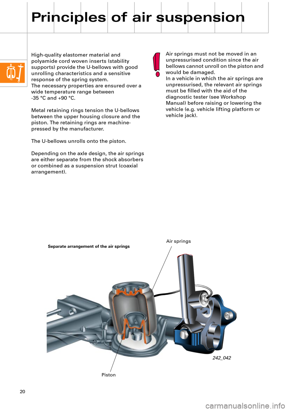
Depending on the axle design, the air springs
are either separate from the shock absorbers
or combined as a suspension strut (coaxial
arrangement).Air springs must not be moved in an
unpressurised condition since the air
bellows cannot unroll on the piston and
would be damaged.
In a vehicle in which the air springs are
unpressurised, the relevant air springs
must be Þlled with the aid of the
diagnostic tester (see Workshop
Manual) before raising or lowering the
vehicle (e.g. vehicle lifting platform or
vehicle jack).
242_042
Separate arrangement of the air springs
PistonAir springs
Page 23 of 64
23
Example of the contour of a piston
(suspension strut in the Audi allroad quattro)
Vibration dampers are available in different
designs but their basic function and purpose
are the same.
Hydraulic/mechanical damping has found
widespread application in modern vehicle
design. The telescopic shock absorber is now
particularly favoured due to its small
dimensions, minimum friction, precise
damping and simple design.
Vibration damping
Without vibration damping, the vibration of
the masses during driving operation would
be increased to such an extent by repeated
road irregularities, that bodywork vibration
would build up increasingly and the wheels
would lose contact with the road surface.
The purpose of the vibration damping system
is to eliminate vibrations (energy) as quickly
as possible via the suspension.
For this purpose, hydraulic vibration dampers
(shock absorbers) are located parallel to the
springs.
242_079
U-bellows
Piston
Compressed
Page 24 of 64
24
Principles of air suspension
As previously mentioned, vibration damping
has a fundamental effect on driving safety
and comfort.
However, the requirements of driving safety
(driving dynamics) and driving comfort are
conßicting.
Within certain limits, the following applies in
principle:
¥ A higher rate of damping improves driving
dynamics and reduces driving comfort.
¥ A lower rate of damping lessens driving
dynamics and improves driving comfort.The term Òshock absorbersÓ is
misleading as it does not precisely
describe the function.
For this reason we shall use the term
Òvibration damperÓ instead.
242_022 Damped vibration
Un-damped vibrationUneven groundDirection of
travel Sprung mass
Unsprung mass