Page 42 of 64

42
Self-levelling suspension, A6
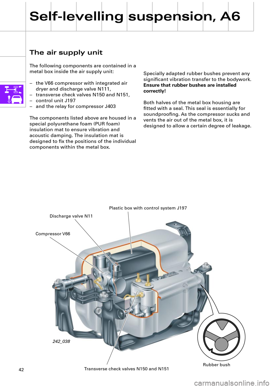
Specially adapted rubber bushes prevent any
signiÞcant vibration transfer to the bodywork.
Ensure that rubber bushes are installed
correctly!
Both halves of the metal box housing are
Þtted with a seal. This seal is essentially for
soundprooÞng. As the compressor sucks and
vents the air out of the metal box, it is
designed to allow a certain degree of leakage.
The air supply unit
The following components are contained in a
metal box inside the air supply unit:
Ð the V66 compressor with integrated air
dryer and discharge valve N111,
Ð transverse check valves N150 and N151,
Ð control unit J197
Ð and the relay for compressor J403
The components listed above are housed in a
special polyurethane foam (PUR foam)
insulation mat to ensure vibration and
acoustic damping. The insulation mat is
designed to Þx the positions of the individual
components within the metal box.
242_038Plastic box with control system J197
Discharge valve N11
Transverse check valves N150 and N151 Compressor V66
Rubber bush
Page 43 of 64
43
Diagram of pneumatic
system
1 Suction Þlter
2 Compressor with motor V66
3 Non-return valve 1
4 Air dryer
5 Non-return valve 2
6 Non-return valve 3
7 Throttle
8 Discharge Þlter
9 Pneumatic discharge valve
123
465
7
9
11
10 Discharge valve N11
11 Valve for suspension strut HL N150
12 Valve for suspension strut HL N151
13 Rear left air spring
14 Rear right air spring
from the relay for
compressor J403from control unit
J197
10
1213242_034
from control unit J197
14
8
Page 44 of 64
44
Self-levelling suspension, A6
The compressor
The compressed air is generated by means of
a single stage piston compressor with
integrated air dryer. In order to avoid oil
contamination of the U-bellows and the dryer
cartridge, the compressor is a so-called dry
running compressor.
Permanently lubricated bearings and a PTFE
(polytetraßuoroethylene) piston ring ensure a
long service life.The discharge valve N111 and the pneumatic
discharge valve are integrated into the dryer
cartridge housing.
In order to protect the compressor from
overheating, it switches off at excess
temperatures (see Overheating protection
chapter, page 61).
Discharge valve N11Pneumatic discharge valve
with pressure limiting valve
Non-return valve 3Air dryer
Non-return valve 1
PTFE piston ring
Suction Þlter
Discharge Þlter
Pressure connector
242_013
Non-return valve 2
Page 46 of 64
46
Self-levelling suspension, A6
Discharge/lowering
The air spring valves N150 and N151 and
discharge valve N111 open during
compression. The air spring pressure ßows to
the pneumatic discharge valve and out of the
system from there via the air dryer and the
pressure limiting valve (see description of
pneumatic discharge valve).
242_056 Pneumatic discharge valve
with pressure limiting valve
Diagram of pneumatic system, discharge
11
12
107
64
9
8
4 Air dryer
6 Non-return valve 3
7 Throttle
8 Discharge Þlter
9 Pneumatic
discharge valve
10 N111
11 N150
12 N151
from control unit J197from control unit J197
242_059
Page 48 of 64
48
Self-levelling suspension, A6
Regeneration
As outlined above, the compressed air is
initially fed through the air dryer and dried.
The moisture is temporarily stored in the air
dryer and the dried compressed air passes
into the system.
Discharge valve N111
The discharge valve N111 is a 3/2 way valve
(three connections and two switching
positions) and is closed without current. The
N111 is used only for discharge purposes
(lowering).
For lowering, the discharge valve is controlled
by the control unit J197 together with valves
N150 and 151.
(see description of the Pneumatic discharge
valve and under Discharge)
242_097
The air dryer is regenerated during discharge
(lowering). During discharge, the dried
compressed air (Òwaste airÓ) is fed back into
the air dryer where it re-absorbs the moisture
stored there and discharges it into the
ambient air.
Air dryer
242_016
Page 49 of 64

49
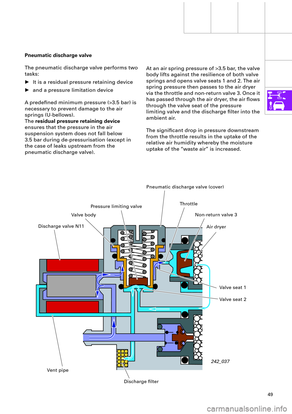
At an air spring pressure of >3.5 bar, the valve
body lifts against the resilience of both valve
springs and opens valve seats 1 and 2. The air
spring pressure then passes to the air dryer
via the throttle and non-return valve 3. Once it
has passed through the air dryer, the air ßows
through the valve seat of the pressure
limiting valve and the discharge Þlter into the
ambient air.
The signiÞcant drop in pressure downstream
from the throttle results in the uptake of the
relative air humidity whereby the moisture
uptake of the Òwaste airÓ is increased. Pneumatic discharge valve
The pneumatic discharge valve performs two
tasks:
¥ It is a residual pressure retaining device
¥ and a pressure limitation device
A predeÞned minimum pressure (>3.5 bar) is
necessary to prevent damage to the air
springs (U-bellows).
The residual pressure retaining device
ensures that the pressure in the air
suspension system does not fall below
3.5 bar during de-pressurisation (except in
the case of leaks upstream from the
pneumatic discharge valve).
242_037 Discharge valve N11Pneumatic discharge valve (cover)
Valve bodyPressure limiting valve
Valve seat 1
Valve seat 2
Discharge Þlter Vent pipeNon-return valve 3
Air dryer Throttle
Page 51 of 64

51
Valve for suspension strut
rear left N150 and rear
right N151
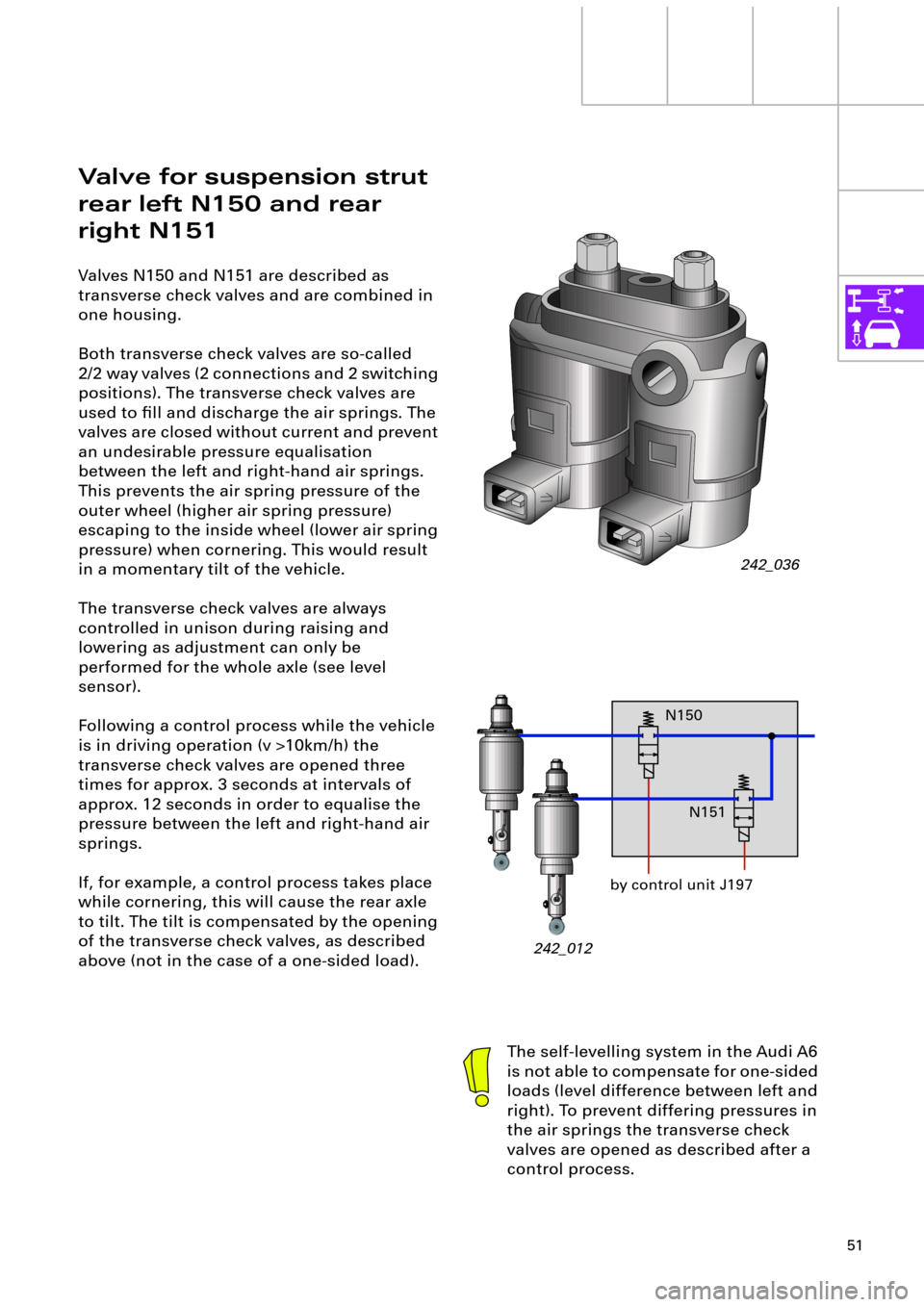
Valves N150 and N151 are described as
transverse check valves and are combined in
one housing.
Both transverse check valves are so-called
2/2 way valves (2 connections and 2 switching
positions). The transverse check valves are
used to Þll and discharge the air springs. The
valves are closed without current and prevent
an undesirable pressure equalisation
between the left and right-hand air springs.
This prevents the air spring pressure of the
outer wheel (higher air spring pressure)
escaping to the inside wheel (lower air spring
pressure) when cornering. This would result
in a momentary tilt of the vehicle.
The transverse check valves are always
controlled in unison during raising and
lowering as adjustment can only be
performed for the whole axle (see level
sensor).
Following a control process while the vehicle
is in driving operation (v >10km/h) the
transverse check valves are opened three
times for approx. 3 seconds at intervals of
approx. 12 seconds in order to equalise the
pressure between the left and right-hand air
springs.
If, for example, a control process takes place
while cornering, this will cause the rear axle
to tilt. The tilt is compensated by the opening
of the transverse check valves, as described
above (not in the case of a one-sided load).
242_036
The self-levelling system in the Audi A6
is not able to compensate for one-sided
loads (level difference between left and
right). To prevent differing pressures in
the air springs the transverse check
valves are opened as described after a
control process.
242_012by control unit J197N150
N151
Page 58 of 64

58
Self-levelling suspension, A6
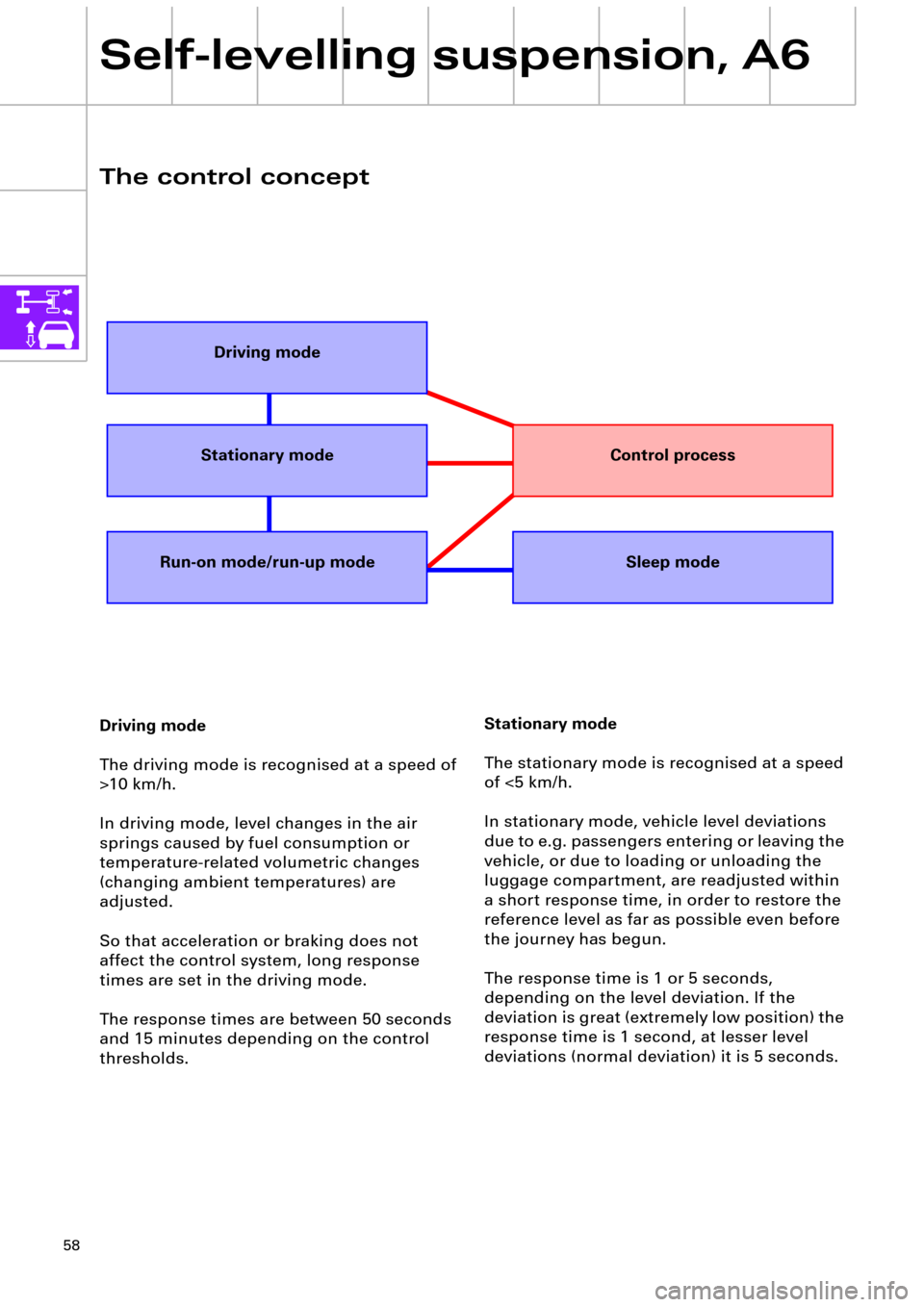
The control concept
Stationary mode
The stationary mode is recognised at a speed
of <5 km/h.
In stationary mode, vehicle level deviations
due to e.g. passengers entering or leaving the
vehicle, or due to loading or unloading the
luggage compartment, are readjusted within
a short response time, in order to restore the
reference level as far as possible even before
the journey has begun.
The response time is 1 or 5 seconds,
depending on the level deviation. If the
deviation is great (extremely low position) the
response time is 1 second, at lesser level
deviations (normal deviation) it is 5 seconds. Driving mode
The driving mode is recognised at a speed of
>10 km/h.
In driving mode, level changes in the air
springs caused by fuel consumption or
temperature-related volumetric changes
(changing ambient temperatures) are
adjusted.
So that acceleration or braking does not
affect the control system, long response
times are set in the driving mode.
The response times are between 50 seconds
and 15 minutes depending on the control
thresholds.
Driving mode
Stationary mode
Run-on mode/run-up modeSleep mode
Control process