Page 33 of 64
33
The PDC damper
In order to maintain the degree of damping
and thereby the handling characteristics at a
constant level between partially and fully
laden, the Audi A6 self-levelling air suspen-
sion and the Audi allroad quattro 4-level air
suspension both have a continuously variable
load recognition system Þtted to the rear axle.
Along with the constant natural frequency of
the bodywork, the vehicle bodywork
maintains virtually constant vibration
characteristics irrespective of the load thanks
to the air springs.
When the vehicle is partially-laden, good
driving comfort is achieved and body
movements are damped sufÞciently Þrmly at
full load.
The PDC damper (Pneumatic Damping
Control) is responsible for this. The damping
force can be varied according to the air spring
pressure.
242_043
PDC valve
Hoses
Air springs
1 1,2 1,4 1,6 1,82,0Body weight ratio
Degree of damping D
PDC damper
Conventional dampers242_057
Coaxial arrangement of air springs/PDC damper
Page 38 of 64

38
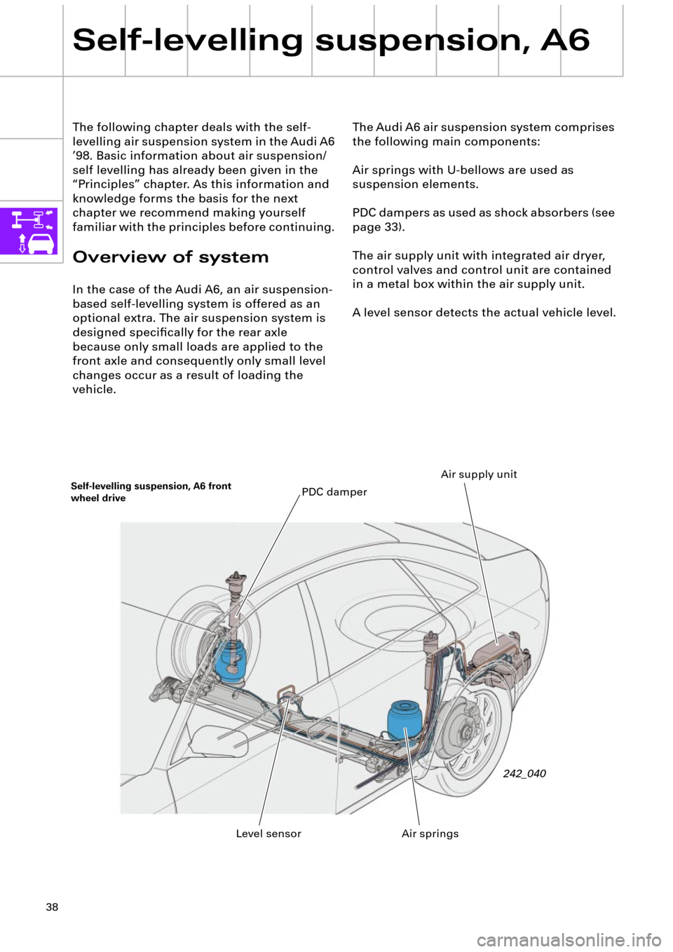
The Audi A6 air suspension system comprises
the following main components:
Air springs with U-bellows are used as
suspension elements.
PDC dampers as used as shock absorbers (see
page 33).
The air supply unit with integrated air dryer,
control valves and control unit are contained
in a metal box within the air supply unit.
A level sensor detects the actual vehicle level. The following chapter deals with the self-
levelling air suspension system in the Audi A6
Õ98. Basic information about air suspension/
self levelling has already been given in the
ÒPrinciplesÓ chapter. As this information and
knowledge forms the basis for the next
chapter we recommend making yourself
familiar with the principles before continuing.
Overview of system
In the case of the Audi A6, an air suspension-
based self-levelling system is offered as an
optional extra. The air suspension system is
designed speciÞcally for the rear axle
because only small loads are applied to the
front axle and consequently only small level
changes occur as a result of loading the
vehicle.
Self-levelling suspension, A6
Self-levelling suspension, A6 front
wheel drive
242_040
Air springs PDC damper
Level sensorAir supply unit
Page 39 of 64
39
¥ Environmentally friendly, uses air
¥ Good operating safety due to great
stability.
¥ Electronic control system with
comprehensive self-diagnosis functions
¥ Maintenance-free Along with the principle advantages of self-
levelling (see Principles), the system realised
in the A6 has the following advantages:
¥ Virtually load-independent suspension
and vibration behaviour.
¥ Little space requirement due to compact
design, especially in the axle area.
¥ Self-levelling even available when engine
is off.
¥ Rapid raising and lowering times
¥ Low energy requirement
Air springs with PDC damperSelf-levelling suspension, A6 quattro
drive
Air supply unit242_041
Page 40 of 64

40
The air springs
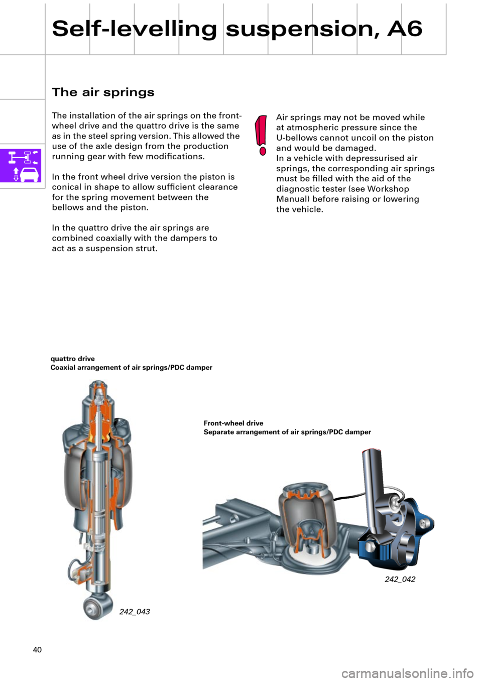
The installation of the air springs on the front-
wheel drive and the quattro drive is the same
as in the steel spring version. This allowed the
use of the axle design from the production
running gear with few modiÞcations.
In the front wheel drive version the piston is
conical in shape to allow sufÞcient clearance
for the spring movement between the
bellows and the piston.
In the quattro drive the air springs are
combined coaxially with the dampers to
act as a suspension strut.
Self-levelling suspension, A6
242_043
quattro drive
Coaxial arrangement of air springs/PDC damper
242_042
Front-wheel drive
Separate arrangement of air springs/PDC damper
Air springs may not be moved while
at atmospheric pressure since the
U-bellows cannot uncoil on the piston
and would be damaged.
In a vehicle with depressurised air
springs, the corresponding air springs
must be Þlled with the aid of the
diagnostic tester (see Workshop
Manual) before raising or lowering
the vehicle.
Page 42 of 64

42
Self-levelling suspension, A6
Specially adapted rubber bushes prevent any
signiÞcant vibration transfer to the bodywork.
Ensure that rubber bushes are installed
correctly!
Both halves of the metal box housing are
Þtted with a seal. This seal is essentially for
soundprooÞng. As the compressor sucks and
vents the air out of the metal box, it is
designed to allow a certain degree of leakage.
The air supply unit
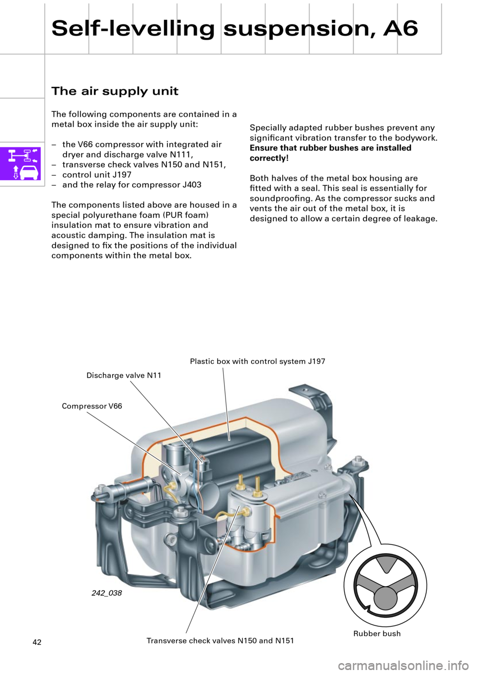
The following components are contained in a
metal box inside the air supply unit:
Ð the V66 compressor with integrated air
dryer and discharge valve N111,
Ð transverse check valves N150 and N151,
Ð control unit J197
Ð and the relay for compressor J403
The components listed above are housed in a
special polyurethane foam (PUR foam)
insulation mat to ensure vibration and
acoustic damping. The insulation mat is
designed to Þx the positions of the individual
components within the metal box.
242_038Plastic box with control system J197
Discharge valve N11
Transverse check valves N150 and N151 Compressor V66
Rubber bush
Page 44 of 64
44
Self-levelling suspension, A6
The compressor
The compressed air is generated by means of
a single stage piston compressor with
integrated air dryer. In order to avoid oil
contamination of the U-bellows and the dryer
cartridge, the compressor is a so-called dry
running compressor.
Permanently lubricated bearings and a PTFE
(polytetraßuoroethylene) piston ring ensure a
long service life.The discharge valve N111 and the pneumatic
discharge valve are integrated into the dryer
cartridge housing.
In order to protect the compressor from
overheating, it switches off at excess
temperatures (see Overheating protection
chapter, page 61).
Discharge valve N11Pneumatic discharge valve
with pressure limiting valve
Non-return valve 3Air dryer
Non-return valve 1
PTFE piston ring
Suction Þlter
Discharge Þlter
Pressure connector
242_013
Non-return valve 2
Page 46 of 64
46
Self-levelling suspension, A6
Discharge/lowering
The air spring valves N150 and N151 and
discharge valve N111 open during
compression. The air spring pressure ßows to
the pneumatic discharge valve and out of the
system from there via the air dryer and the
pressure limiting valve (see description of
pneumatic discharge valve).
242_056 Pneumatic discharge valve
with pressure limiting valve
Diagram of pneumatic system, discharge
11
12
107
64
9
8
4 Air dryer
6 Non-return valve 3
7 Throttle
8 Discharge Þlter
9 Pneumatic
discharge valve
10 N111
11 N150
12 N151
from control unit J197from control unit J197
242_059
Page 48 of 64
48
Self-levelling suspension, A6
Regeneration
As outlined above, the compressed air is
initially fed through the air dryer and dried.
The moisture is temporarily stored in the air
dryer and the dried compressed air passes
into the system.
Discharge valve N111
The discharge valve N111 is a 3/2 way valve
(three connections and two switching
positions) and is closed without current. The
N111 is used only for discharge purposes
(lowering).
For lowering, the discharge valve is controlled
by the control unit J197 together with valves
N150 and 151.
(see description of the Pneumatic discharge
valve and under Discharge)
242_097
The air dryer is regenerated during discharge
(lowering). During discharge, the dried
compressed air (Òwaste airÓ) is fed back into
the air dryer where it re-absorbs the moisture
stored there and discharges it into the
ambient air.
Air dryer
242_016