Page 9 of 26
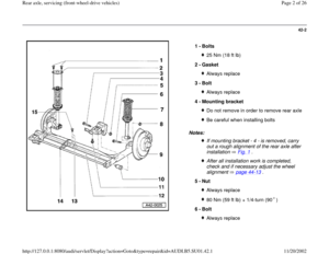
42-7
Fig. 2 Installing retaining strap
- Press center of stabilizer bar toward axle beam.
Dimension -a-: approx. 8 mm (5/16 in.)
Note:
If the axle beam is supplied with pre-drilled holes for mounting retaining
strap guide -b-, the guide must be used. Guide -b- correctly positions the
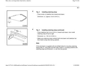
retaining strap and dimension -a- can then be ignored. Fig. 3 Installing retaining strap (continued)
- Press stabilizer bar 8 mm (5/16 in.) toward axle beam, then install
retaining strap off-set to right.
Dimension -a-: 100 mm (3.94 in.)
- Make sure retaining strap contacts both axle beam and stabilizer bar
then fasten strap (lock facing upward).
Pa
ge 9 of 26 Rear axle, servicin
g (front-wheel-drive vehicles
)
11/20/2002 htt
p://127.0.0.1:8080/audi/servlet/Dis
play?action=Goto&t
yp
e=re
pair&id=AUDI.B5.SU01.42.1
Page 10 of 26
42-8
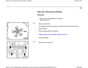
Rear axle, removing and installing
Removing
Vehicle must be standing on its wheels
above vehicle lift
Repair Manual, Brake System, Repair Group 47
- Remove wheel trim.
On light alloy wheels use puller in vehicle tool kit to remove trim cap
- Raise vehicle.
- Extract brake fluid from reservoir:
- Remove wheels.
- Remove cover (arrows).
Pa
ge 10 of 26 Rear axle, servicin
g (front-wheel-drive vehicles
)
11/20/2002 htt
p://127.0.0.1:8080/audi/servlet/Dis
play?action=Goto&t
yp
e=re
pair&id=AUDI.B5.SU01.42.1
Page 11 of 26
42-9
- Unbolt heat shield cover (arrows indicate bolted connections) and push
forward until parking brake cable adjuster becomes accessible.
- Loosen both cable adjusters as follows:
- Remove locking clip -D-.
- Screw in adjusting nut -C- up to stop.
- Push adjuster together.
Pa
ge 11 of 26 Rear axle, servicin
g (front-wheel-drive vehicles
)
11/20/2002 htt
p://127.0.0.1:8080/audi/servlet/Dis
play?action=Goto&t
yp
e=re
pair&id=AUDI.B5.SU01.42.1
Page 12 of 26
42-10
- Remove locking plates -1- on left and right-sides, slightly loosen bolts -
2- for cable retaining plate, and remove cables from axle beam.
- Disconnect brake lines at rear axle (arrow) on both sides.
Pa
ge 12 of 26 Rear axle, servicin
g (front-wheel-drive vehicles
)
11/20/2002 htt
p://127.0.0.1:8080/audi/servlet/Dis
play?action=Goto&t
yp
e=re
pair&id=AUDI.B5.SU01.42.1
Page 13 of 26
42-11
- Pull ABS wheel speed sensors out of mounting
holes on both sides.
- Detach ABS wheel speed sensor wiring from
rear axle.
- On vehicles with headlight range control remove
linkage from axle beam.
Note:
Use VAG1383 gearbox lifter together with 1359/2
attachment for removing and installing the axle
beam.
- Unbolt and remove suspension strut from axle beam.
- Remove bolts from guide bushings ( page 42
-2 , items -3- and -5-)
and remove axle beam.
Pa
ge 13 of 26 Rear axle, servicin
g (front-wheel-drive vehicles
)
11/20/2002 htt
p://127.0.0.1:8080/audi/servlet/Dis
play?action=Goto&t
yp
e=re
pair&id=AUDI.B5.SU01.42.1
Page 14 of 26
42-12
Installing
- Install axle together with guide bushings into
mounting brackets and install bolts hand-tight.
- Install suspension struts and hand-tighten
suspension strut to axle beam bolts.
- Coat O-ring for ABS wheel speed sensor with
brake cylinder paste.
Repair Manual, Brake System, Repair Group 46
Repair Manual, Brake System, Repair Group 47 - Push ABS wheel speed sensors into wheel bearing housings up to
stop.
- Install locking plates for ABS wheel speed sensors.
- Route parking brake cables and attach to brake calipers.
- Connect brake lines.
- Adjust parking brake:
- Install heat shield.
- Bleed brakes:
Pa
ge 14 of 26 Rear axle, servicin
g (front-wheel-drive vehicles
)
11/20/2002 htt
p://127.0.0.1:8080/audi/servlet/Dis
play?action=Goto&t
yp
e=re
pair&id=AUDI.B5.SU01.42.1
Page 15 of 26
42-13
CAUTION!
Vehicle must be standing on its wheels when
tightening guide bushing to rear axle bolts.
Otherwise bonded rubber bushings will be
subjected to torsion resulting in shortened
service life
- Tighten guide bushing bolts ( page 42
-2 ,
items -3- and -5-).
Tightening torque: 80 Nm (59 ft lb) + 1/4-turn
(90 )
CAUTION!
Vehicle must be standing on its wheels when
tightening suspension strut to rear axle bolts.
Otherwise bonded rubber bushings will be
subjected to torsion resulting in shortened
service life
- Tighten suspension strut to axle beam bolts (
page 42
-2 , items -6- and -8-).
Tightening torque: 50 Nm (37 ft lb) + 1/4-turn
(90 )
-
On vehicles with headlight range control, tighten
bolted connection between headlight range
Pa
ge 15 of 26 Rear axle, servicin
g (front-wheel-drive vehicles
)
11/20/2002 htt
p://127.0.0.1:8080/audi/servlet/Dis
play?action=Goto&t
yp
e=re
pair&id=AUDI.B5.SU01.42.1
Page 16 of 26
control linkage to axle beam.
Tightening torque: 3 Nm +1/-0 Nm (27 in. lb +9/-
0 in. lb)
- Install cover below rear axle.
- Check wheel alignment and adjust if necessary
page 44
-6 .
Pa
ge 16 of 26 Rear axle, servicin
g (front-wheel-drive vehicles
)
11/20/2002 htt
p://127.0.0.1:8080/audi/servlet/Dis
play?action=Goto&t
yp
e=re
pair&id=AUDI.B5.SU01.42.1


Note:
If the axle beam is supplied with pre-drilled")

 and push
forward until parking brake cable adjuster becomes accessible.
- Loosen both cable adjusters as follows:")


- Install cover below rear axle.
- Check wheel alignment and adjust if necessary
pag")