Page 9 of 23
39-80
- Remove heat shields above driveshaft.
- Unbolt heat shield for driveshaft from cover for Torsen differential
(arrows).
Note:
Only mark location, if same driveshaft is going to be reinstalled. - Check whether there is a factory marking (colored dot -arrows-) on
driveshaft and at flange/driveshaft at rear final drive. If not, mark
location of driveshaft flange -A- to rear final drive -B- with color.
Pa
ge 9 of 23 Driveshaft, servicin
g
11/20/2002 htt
p://127.0.0.1:8080/audi/servlet/Dis
play?action=Goto&t
yp
e=re
pair&id=AUDI.B5.AT01.39.5
Page 10 of 23
39-81
- Remove mounting bolts for both driveshaft
flanges.
- Remove upper three mounting bolts for each
driveshaft constant velocity joint.
- Back off mounting bolts for center support
slightly.
Only for carbon fiber driveshafts:
Spacer pieces are attached to 3405 alignment fixture via a chain.
Arrow -A- points in direction of travel.
WARNING!
Assembly tool must rest on both steel rings -1- before tightening
plastic nut -A-. If that is not the case, the surface of the carbon fiber
driveshaft can be damaged and must be replaced see Important
notes Page 39
-74
- Place spacer pieces -2- onto 3405 alignment fixture (distance
dimension = 10 mm).
- Using spacer pieces -2-, hook in 3405 alignment fixture according to
illustration.
Pa
ge 10 of 23 Driveshaft, servicin
g
11/20/2002 htt
p://127.0.0.1:8080/audi/servlet/Dis
play?action=Goto&t
yp
e=re
pair&id=AUDI.B5.AT01.39.5
Page 11 of 23
39-82
Note:
Never set alignment fixture on balance plates.
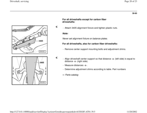
For all driveshafts except for carbon fiber driveshafts: - Carefully tighten plastic nuts -A- and -B-.
Note:
Never set alignment fixture on balance plates.
For all driveshafts, also for carbon fiber driveshafts:
Note:
Only store and move driveshaft fully extended. - Attach 3405 alignment fixture and tighten plastic nuts.
- Remove mounting bolts for flanges to transmission and to rear final
drive as well as mounting bolts of center support.
- Push driveshaft to rear final drive together. The constant velocity joints
can be adjusted axially.
- Guide driveshaft out of transmission flange using assembly tool.
Pa
ge 11 of 23 Driveshaft, servicin
g
11/20/2002 htt
p://127.0.0.1:8080/audi/servlet/Dis
play?action=Goto&t
yp
e=re
pair&id=AUDI.B5.AT01.39.5
Page 12 of 23
39-83
Installing
Installation is reverse of removal, noting the
following:
- Observe important notes page 39
-73
Notes:
After removing driveshaft, always remove any
remaining locking fluid from thread holes in the
transmission drive flanges and the rear final
drive. Otherwise there is a possibility that the
new bolts may get jammed when installed and
shear when removed.
Cleaning can be performed with a tap.
Replace gaskets on drive flanges (remove
protective film and attach gasket to drive
flanges). Adhesive surface must be free of
grease.
To prevent imbalance, driveshaft flanges -A- and rear final drive
flanges -B- must be installed so that the factory color markings or
markings which were made afterward are aligned (arrows).
Pa
ge 12 of 23 Driveshaft, servicin
g
11/20/2002 htt
p://127.0.0.1:8080/audi/servlet/Dis
play?action=Goto&t
yp
e=re
pair&id=AUDI.B5.AT01.39.5
Page 13 of 23
39-84
Repair Manual, Engine Mechanical, Repair Group 26; removing and
installing exhaust system If a new driveshaft is installed and the factory color marking on the
rear final drive flange is no longer visible, check radial run out at
flange/driveshaft page 39
-86
and adjust color marking at driveshaft
to new marking at flange.
After disconnecting driveshaft from rear final drive, an additional
balance washer (thick washer) that may be located between shim and
bolt head may not be reinstalled. Replace driveshaft bolts (self-locking).
- Adjust driveshaft after installing page 39
-88
.
- Install exhaust system free of stress:
Pa
ge 13 of 23 Driveshaft, servicin
g
11/20/2002 htt
p://127.0.0.1:8080/audi/servlet/Dis
play?action=Goto&t
yp
e=re
pair&id=AUDI.B5.AT01.39.5
Page 14 of 23
39-85
Tightening torques
Component
Nm
Driveshaft to transmission
(Output flange) 55
Driveshaft to final drive
(Input flange) 55
Center driveshaft support to body 23
Heat shield for driveshaft to transmission 23
Crossmember to body 25
Nuts for clamping sleeve 40
Pa
ge 14 of 23 Driveshaft, servicin
g
11/20/2002 htt
p://127.0.0.1:8080/audi/servlet/Dis
play?action=Goto&t
yp
e=re
pair&id=AUDI.B5.AT01.39.5
Page 15 of 23
39-86
Radial play at driveshaft flange,
measuring and marking
Special tools and equipment
VW387 dial gauge holder
2024A Engine SlingDial gage Bolt M10 x 85
Pa
ge 15 of 23 Driveshaft, servicin
g
11/20/2002 htt
p://127.0.0.1:8080/audi/servlet/Dis
play?action=Goto&t
yp
e=re
pair&id=AUDI.B5.AT01.39.5
Page 16 of 23

39-87
Notes:
Always measure radial run-out if torque tube
has been removed. Make new color marking
and remove old color marking.
If a new driveshaft is installed and the color
marking on the drive flange of the rear final
drive is no longer visible, location of largest
radial run-out must be determined and marked
with a color marking.
Align this colored dot with colored dot on
driveshaft page 39
-83
.
Radial run-out can also be measured with the
rear final drive installed, for this the driveshaft
must be disconnected from the rear final drive.
Observe notes page 39
-73
.
- Remove left front bolt at transmission mount for
rear final drive.
- Remove strap from 2024A engine sling and tighten at empty hole using
an M10 x 85 mm -2- bolt. Place 5 M12 nuts -1- under strap.
- Bolt VW387 dial gauge holder to strap in this position.
- Set dial indicator onto ground diameter (arrow) in driveshaft flange and
set to "0" with 1 mm preload.
Pa
ge 16 of 23 Driveshaft, servicin
g
11/20/2002 htt
p://127.0.0.1:8080/audi/servlet/Dis
play?action=Goto&t
yp
e=re
pair&id=AUDI.B5.AT01.39.5


.
Note:
Only mark location, if same driveshaft is go")


 55
Driveshaft to final drive
(Input flange) 55
Center driveshaft support to body 23
He")
