Page 1487 of 3115

F05340
TOYOTA Hand-held Tester
DLC3
DI239-15
N09214
DLC3 DI-658
- DIAGNOSTICSPOWER TILT AND POWER TELESCOPIC STEERING
COLUMN
851 Author�: Date�:
2004 LAND CRUISER (RM1071U)
PRE-CHECK
1. DESCRIPTION
(a) DIAGNOSIS SYSTEM
When troubleshooting Multiplex OBD (M-OBD) vehicles,
the only difference from the usual troubleshooting proce-
dure is that you connect the TOYOTA hand-held tester
to vehicle, and read off various data output from the ve-
hicle's Power Tilt and Telescopic Steering ECU.
The Power Tilt and Telescopic Steering ECU records the
applicable DTCs when the computer detects a malfunc-
tion in the computer itself or its circuit.
To check the DTCs, connect a TOYOTA hand-held tester
to DLC3 on the vehicle. The TOYOTA hand-held tester
enables you to erase the DTCs and activate the several
actuators and check freeze frame data and various forms
on steering data.
(b) DATA LINK CONNECTOR 3 (DLC3)
The Power Tilt and Telescopic Steering ECU uses ISO
14230 for communication. The terminal arrangement of
DLC3 complies with SAE J1962 and matches the ISO
14230 format.
Terminal No.ConnectionVoltage or ResistanceCondition
7Bus + LinePulse generationDuring transmission
4Chassis Grounde Body Ground 1 W or lessAlways
5Signal Grounde Body Ground 1 W or lessAlways
16Battery Positivee Body Ground 9 - 14 VAlways
HINT:
If your display shows ºUNABLE TO CONNECT TO VEHICLEº
when you have connected the cable of TOYOTA hand-held
tester to DLC3, turned the ignition switch ON and operated the
TOYOTA hand-held tester, there is a problem on the vehicle
side or tester side.
�If communication is normal when the tester is connected
to another vehicle, inspect DLC3 on the original vehicle.
�If communication is still not possible when the tester is
connected to another vehicle, the problem is probably in
the tester itself, so consult the Service Department listed
in the tester's Operator's Manual.
Page 1488 of 3115
F05340
TOYOTA Hand-held Tester
DLC3
- DIAGNOSTICSPOWER TILT AND POWER TELESCOPIC STEERING
COLUMNDI-659
852 Author�: Date�:
2004 LAND CRUISER (RM1071U)
2. DIAGNOSIS INSPECTION
(a) Check the DTC.
(1) Prepare the TOYOTA hand-held tester.
(2) Connect the TOYOTA hand-held tester to DLC3 at
the lower of the instrument panel.
(3) Turn the ignition switch ON and turn the TOYOTA
hand-held tester switch ON.
(4) Use the TOYOTA hand-held tester to check the
DTCs and freeze frame data, note or print them
(See the Operator's Manual for operating instruc-
tions.).
(5) See page DI-660 to confirm the details of the DTC.
(b) Clear the DTC.
The following actions will erase the DTC and freeze frame
data.
�When using the TOYOTA hand-held tester:
Operating the TOYOTA hand-held tester to erase
the DTCs (See the Operator's Manual for operating
instructions.).
�When not using the TOYOTA hand-held tester:
Disconnecting the battery terminals.
Page 1489 of 3115

DI23D-13
- DIAGNOSTICSPOWER TILT AND POWER TELESCOPIC STEERING
COLUMNDI-663
856 Author�: Date�:
2004 LAND CRUISER (RM1071U)
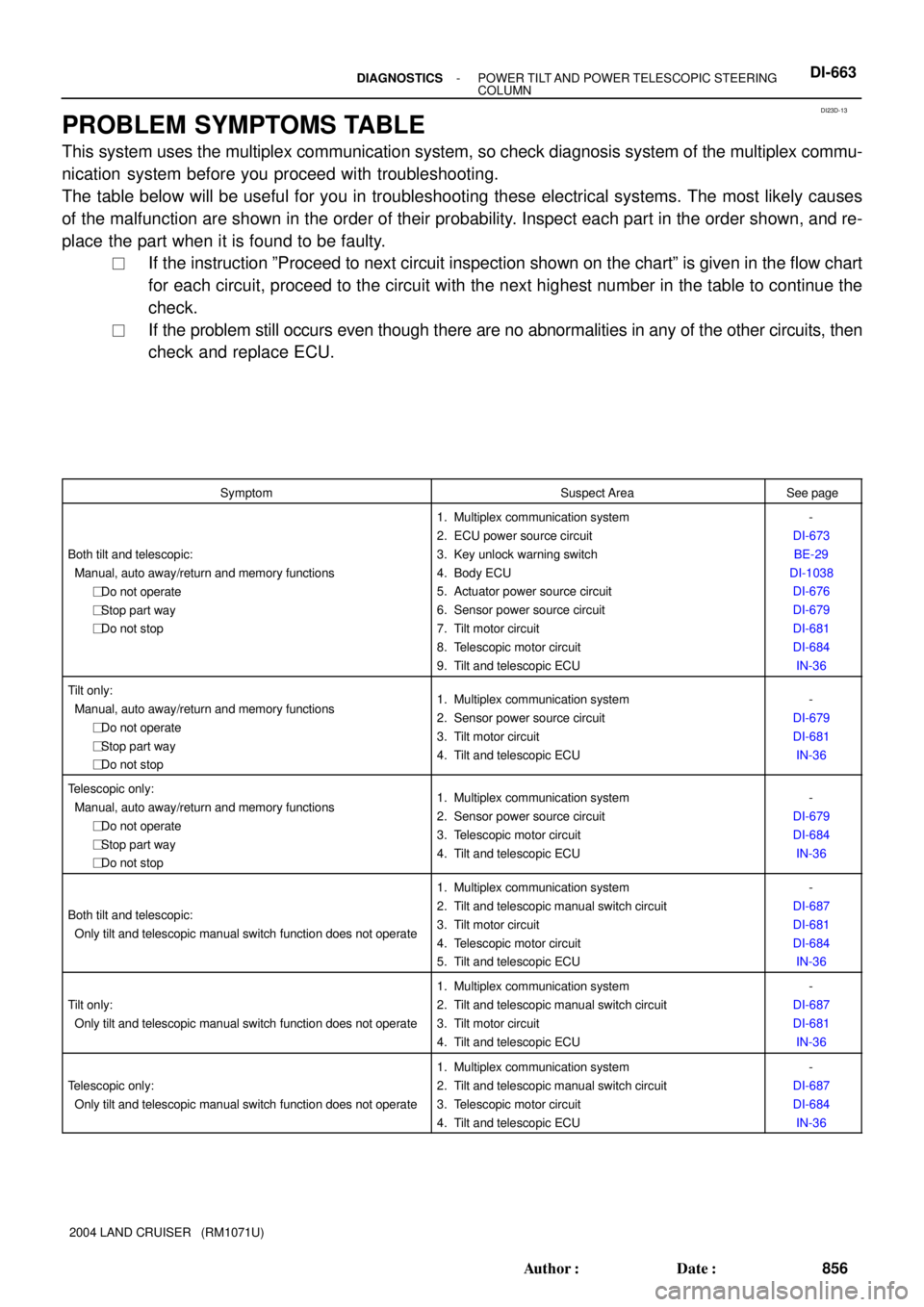
PROBLEM SYMPTOMS TABLE
This system uses the multiplex communication system, so check diagnosis system of the multiplex commu-
nication system before you proceed with troubleshooting.
The table below will be useful for you in troubleshooting these electrical systems. The most likely causes
of the malfunction are shown in the order of their probability. Inspect each part in the order shown, and re-
place the part when it is found to be faulty.
�If the instruction ºProceed to next circuit inspection shown on the chartº is given in the flow chart
for each circuit, proceed to the circuit with the next highest number in the table to continue the
check.
�If the problem still occurs even though there are no abnormalities in any of the other circuits, then
check and replace ECU.
SymptomSuspect AreaSee page
Both tilt and telescopic:
Manual, auto away/return and memory functions
��� Do not operate
��� Stop part way
��� Do not stop
1. Multiplex communication system
2. ECU power source circuit
3. Key unlock warning switch
4. Body ECU
5. Actuator power source circuit
6. Sensor power source circuit
7. Tilt motor circuit
8. Telescopic motor circuit
9. Tilt and telescopic ECU-
DI-673
BE-29
DI-1038
DI-676
DI-679
DI-681
DI-684
IN-36
Tilt only:
Manual, auto away/return and memory functions
��� Do not operate
��� Stop part way
��� Do not stop1. Multiplex communication system
2. Sensor power source circuit
3. Tilt motor circuit
4. Tilt and telescopic ECU-
DI-679
DI-681
IN-36
Telescopic only:
Manual, auto away/return and memory functions
��� Do not operate
��� Stop part way
��� Do not stop1. Multiplex communication system
2. Sensor power source circuit
3. Telescopic motor circuit
4. Tilt and telescopic ECU-
DI-679
DI-684
IN-36
Both tilt and telescopic:
Only tilt and telescopic manual switch function does not operate
1. Multiplex communication system
2. Tilt and telescopic manual switch circuit
3. Tilt motor circuit
4. Telescopic motor circuit
5. Tilt and telescopic ECU-
DI-687
DI-681
DI-684
IN-36
Tilt only:
Only tilt and telescopic manual switch function does not operate
1. Multiplex communication system
2. Tilt and telescopic manual switch circuit
3. Tilt motor circuit
4. Tilt and telescopic ECU-
DI-687
DI-681
IN-36
Telescopic only:
Only tilt and telescopic manual switch function does not operate
1. Multiplex communication system
2. Tilt and telescopic manual switch circuit
3. Telescopic motor circuit
4. Tilt and telescopic ECU-
DI-687
DI-684
IN-36
Page 1490 of 3115
DI-664- DIAGNOSTICSPOWER TILT AND POWER TELESCOPIC STEERING
COLUMN
857 Author�: Date�:
2004 LAND CRUISER (RM1071U)Symptom
Suspect AreaSee page
Both away and return:
Only auto away/return function does not operate
1. Check status of auto away function using TOYOTA
hand-held tester
2. Multiplex communication system
3. Ignition switch
4. Key unlock warning switch
5. Tilt motor circuit
6. Telescopic motor circuit
7. Tilt and telescopic ECU
-
-
BE-29
BE-29
DI-681
DI-684
IN-36
Only away:
Only Auto away/return function does not operate
1. Multiplex communication system
2. Key unlock warning switch
3. Ignition switch
4. Tilt motor circuit
5. Telescopic motor circuit
6. Tilt and telescopic ECU-
BE-29
BE-29
DI-681
DI-684
IN-36
Only return:
Only auto away/return function does not operate
1. Multiplex communication system
2. Key unlock warning switch
3. Ignition switch
4. Tilt motor circuit
5. Telescopic motor circuit
6. Tilt and telescopic ECU-
BE-29
BE-29
DI-681
DI-684
IN-36
Page 1491 of 3115

DI23C-14
F05341
1
1 3
8 2
2
9 3 4
10 11 12 13 14 15 16765
4 5 6 87
T7T8
DI-662- DIAGNOSTICSPOWER TILT AND POWER TELESCOPIC STEERING
COLUMN
855 Author�: Date�:
2004 LAND CRUISER (RM1071U)
TERMINALS OF ECU
Symbols (Terminals No.)Wiring ColorConditionSTD Voltage (V)
IG (T7 4) GND (T7 6)BW WBIG switch ON10 - 14 (DC)IG (T7-4) - GND (T7-6)B-W - W-BIG switch LOCKBelow 1 (DC)
VC (T7-2) - GND (T7-6)V - W-BAlways4.5 - 5.5 (DC)
GND (T7-6) - Body GroundW-B -
Body GroundAlwaysBelow 1 (DC)
ECUB (T7-1) - Body GroundL-W -
Body GroundAlways10 - 14 (DC)
ECUB (T7-1) - GND (T7-6)L-W - W-BAlways10 - 14 (DC)
Tilt up by manual switch1.30 - 1.70 (DC)
Tilt down by manual switch0.30 - 0.50 (DC)
MSW (T7-5) - GND (T7-6)V-Y - W-BTelescopic extended by manual switch2.05 - 2.75 (DC)MSW (T7 5) GND (T7 6)VY WB
Telescopic contracted by manual switch0.65 - 0.95 (DC)
Manual switch is not operatingBelow 0.20 (DC)
+B (T8-4) - GND (T7-6)G-B - W-BAlways10 - 14 (DC)
S5V1 (T8-13) - SG1 (T8-14)G-W - G-YIG switch ON4.5 - 5.5 (DC)
S5V2 (T8-12) - SG2 (T8-10)B-W - B-YIG switch ON4.5 - 5.5 (DC)
A1 (T8-7) - COM1 (T8-15)P - GIG switch ON, tilt up or down by manual switch190 - 230 (AC)
B1 (T8-16) - COM1 (T8-15)V - GIG switch ON, tilt up or down by manual switch190 - 230 (AC)
A2 (T8-1) - COM2 (T8-9)W - BIG switch ON, telescopic extend or contracted by manual switch190 - 230 (AC)
B2 (T8-8) - COM2 (T8-9)G - BIG switch ON, telescopic extend or contracted by manual switch190 - 230 (AC)
Page 1492 of 3115
DI3IY-09
H05146
A28
D Squib
Spiral CableY-B
Y1
II4
2
II4Y-B
YAirbag Sensor Assembly
14
C26
13D+
D- 1
2
C26
- DIAGNOSTICSSUPPLEMENTAL RESTRAINT SYSTEM
DI-71 1
904 Author�: Date�:
2004 LAND CRUISER (RM1071U)
CIRCUIT INSPECTION
DTC B0100/13 Short in D Squib Circuit
CIRCUIT DESCRIPTION
The D squib circuit consists of the airbag sensor assembly, the spiral cable and the steering wheel pad.
It causes the airbag to deploy when the airbag deployment conditions are satisfied.
For details of the function of each component, see OPERATION on page RS-3.
DTC B0100/13 is recorded when a short is detected in the D squib circuit.
DTC No.DTC Detecting ConditionTrouble Area
B0100/13
�Short in D squib circuit
�D squib malfunction
�Spiral cable malfunction
�Airbag sensor assembly malfunction�Steering wheel pad (D squib)
�Spiral cable
�Airbag sensor assembly
�Dash wire
�Column wire
WIRING DIAGRAM
Page 1493 of 3115
H19229H21259H20678
D Squib
D+
(-) (+) D-
Spiral
CableAirbag
Sensor
Assembly
DI-712
- DIAGNOSTICSSUPPLEMENTAL RESTRAINT SYSTEM
905 Author�: Date�:
2004 LAND CRUISER (RM1071U)
INSPECTION PROCEDURE
1 Prepare for inspection (See step 1 on page DI-923).
2 Check connector.
CHECK:
Make sure that the orange spiral cable connector is not damaged.
OK:
The lock button is not disengaged, or the claw of the lock is not deformed or damaged.
NG Replace spiral cable.
OK
3 Check D squib circuit.
PREPARATION:
Release the airbag activation prevention mechanism built in the
connector on the airbag sensor assembly side between the
steering wheel pad (D squib) and the airbag sensor assembly
(See page DI-692).
CHECK:
Measure the resistance between D+ and D- of the orange con-
nector on the steering wheel pad (D squib) side between the air-
bag sensor assembly and the steering wheel pad (D squib).
OK:
Resistance: 1 MW or Higher
NG Go to step 6.
OK
Page 1495 of 3115

AB0119FI1390H10600
H21267
H20680
D Squib
Airbag
Sensor
Assembly
CG
TCON
DTC B0100/13
DLC3
" uSpiral
Cable
DI-714
- DIAGNOSTICSSUPPLEMENTAL RESTRAINT SYSTEM
907 Author�: Date�:
2004 LAND CRUISER (RM1071U)
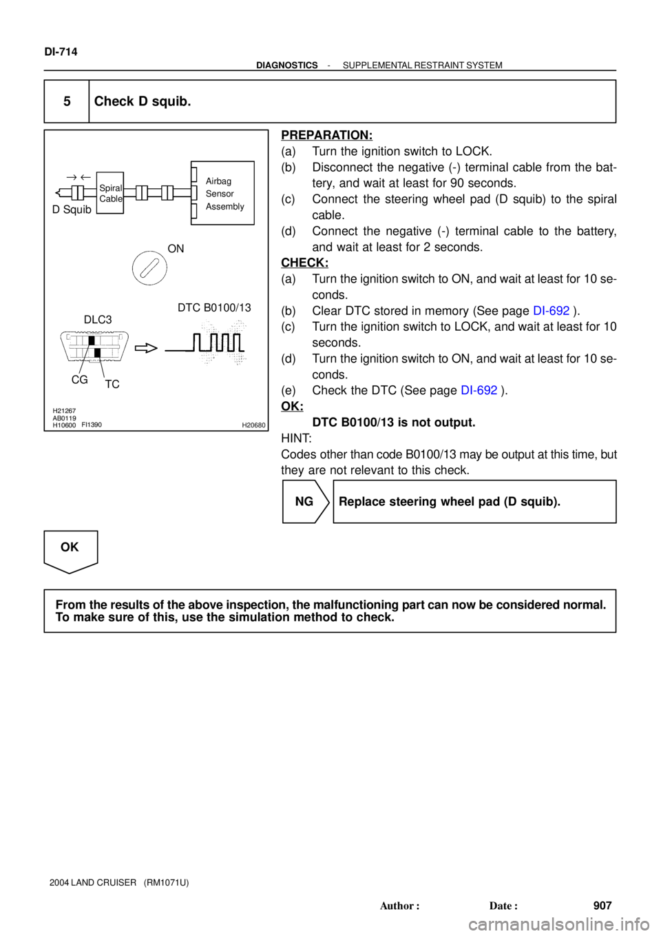
5 Check D squib.
PREPARATION:
(a) Turn the ignition switch to LOCK.
(b) Disconnect the negative (-) terminal cable from the bat-
tery, and wait at least for 90 seconds.
(c) Connect the steering wheel pad (D squib) to the spiral
cable.
(d) Connect the negative (-) terminal cable to the battery,
and wait at least for 2 seconds.
CHECK:
(a) Turn the ignition switch to ON, and wait at least for 10 se-
conds.
(b) Clear DTC stored in memory (See page DI-692).
(c) Turn the ignition switch to LOCK, and wait at least for 10
seconds.
(d) Turn the ignition switch to ON, and wait at least for 10 se-
conds.
(e) Check the DTC (See page DI-692).
OK:
DTC B0100/13 is not output.
HINT:
Codes other than code B0100/13 may be output at this time, but
they are not relevant to this check.
NG Replace steering wheel pad (D squib).
OK
From the results of the above inspection, the malfunctioning part can now be considered normal.
To make sure of this, use the simulation method to check.