Page 1587 of 3115

3 Check airbag sensor assembly.
PREPA")
H15222
ON
Airbag
Sensor
Assembly
DLC3
CGTC
DTC B1135/24
H17184
DI-806
- DIAGNOSTICSSUPPLEMENTAL RESTRAINT SYSTEM
999 Author�: Date�:
2004 LAND CRUISER (RM1071U)
3 Check airbag sensor assembly.
PREPARATION:
(a) Connect the connectors to the airbag sensor assembly.
(b) Connect the negative (-) terminal cable to the battery,
and wait at least for 2 seconds.
CHECK:
(a) Turn the ignition switch to ON, and wait at least for 10 se-
conds.
(b) Clear the DTC stored in memory (See page DI-692).
(c) Turn the ignition switch to LOCK, and wait at least for 10
seconds.
(d) Turn the ignition switch to ON, and wait at least for 10 se-
conds.
(e) Check the DTC (See page DI-692).
OK:
DTC B1135/24 is not output.
HINT:
Codes other than code B1135/24 may be output at this time, but
they are not relevant to this check.
OK Complete.
NG
4 Perform a visual check of the disconnection detection pin.
OK:
No deformation is identified.
HINT:
Compare it with the other 2 connector pins.
NG Repair or replace wire harness.
OK
Replace airbag sensor assembly.
Page 1588 of 3115

(*1)
(*1)
(*1)
*1: w/ Side Air")
H01450
S12
Side and Curtain Shield
Airbag Sensor Assembly RHAirbag Sensor Assembly
GR LG
L-Y
P SSR-
ESR
SSR+
VUPR4 3 2
1C2713
15
16
17SSR-
ESR
SSR+
VUPR C27
C27
C27 (*1)
(*1)
(*1)
(*1)
*1: w/ Side Airbag
- DIAGNOSTICSSUPPLEMENTAL RESTRAINT SYSTEM
DI-807
1000 Author�: Date�:
2004 LAND CRUISER (RM1071U)
DTC B1140/32 Side and Curtain Shield Airbag Sensor
Assembly RH Malfunction
CIRCUIT DESCRIPTION
The side and curtain shield airbag sensor assembly RH consists of the safing sensor, diagnosis circuit and
lateral deceleration sensor, etc.
It receives signals from the lateral deceleration sensor, judges whether or not the SRS must be activated,
and detects diagnosis system malfunction.
DTC B1140/32 is recorded when occurrence of a malfunction in the side and curtain shield airbag sensor
assembly RH is detected.
DTC No.DTC Detecting ConditionTrouble Area
B1140/32�Side and curtain shield airbag sensor assembly RH mal-
function�Side and curtain shield airbag sensor assembly RH
�Floor No. 2 wire
�Airbag sensor assembly
HINT:
DTC B1140/32 is indicated only for the vehicle equipped with the side airbag.
WIRING DIAGRAM
DIB3T-01
Page 1589 of 3115
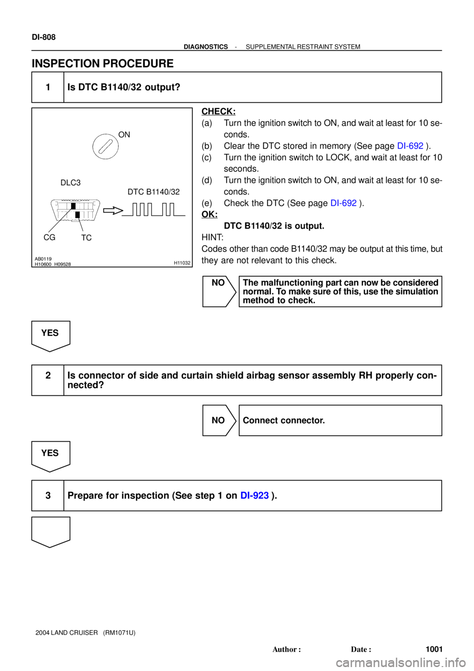
H09528AB0119H10600H11032
ON
CG
TCDTC B1140/32
DLC3
DI-808
- DIAGNOSTICSSUPPLEMENTAL RESTRAINT SYSTEM
1001 Author�: Date�:
2004 LAND CRUISER (RM1071U)
INSPECTION PROCEDURE
1 Is DTC B1140/32 output?
CHECK:
(a) Turn the ignition switch to ON, and wait at least for 10 se-
conds.
(b) Clear the DTC stored in memory (See page DI-692).
(c) Turn the ignition switch to LOCK, and wait at least for 10
seconds.
(d) Turn the ignition switch to ON, and wait at least for 10 se-
conds.
(e) Check the DTC (See page DI-692).
OK:
DTC B1140/32 is output.
HINT:
Codes other than code B1140/32 may be output at this time, but
they are not relevant to this check.
NO The malfunctioning part can now be considered
normal. To make sure of this, use the simulation
method to check.
YES
2 Is connector of side and curtain shield airbag sensor assembly RH properly con-
nected?
NO Connect connector.
YES
3 Prepare for inspection (See step 1 on DI-923).
Page 1590 of 3115
H01015H16862H19233H19263
Airbag
Sensor
Assembly
(-) (+) Side and Curtain
Shield Airbag
Sensor Assembly RH
Airbag Sensor
Assembly
SSR-
SSR+
SSR-
SSR+
Floor No. 2 Wire
- DIAGNOSTICSSUPPLEMENTAL RESTRAINT SYSTEM
DI-809
1002 Author�: Date�:
2004 LAND CRUISER (RM1071U)
4 Check floor No. 2 wire.
PREPARATION:
Using a service wire, connect SSR+ and SSR- of the floor No.
2 wire connector on the side and curtain shield airbag sensor
assembly RH side.
CHECK:
Measure the resistance between SSR+ and SSR- of the floor
No. 2 wire connector on the airbag sensor assembly side.
OK:
Resistance: Below 1 W
NG Repair or replace floor No. 2 wire.
OK
Page 1591 of 3115
H01015
H16863H19234H19264
Airbag
Sensor
Assembly
(-)(+)VUPRAirbag Sensor
Assembly
ESR
VUPRESR Side and Curtain
Shield Airbag
Sensor Assembly RH
Floor No. 2 Wire
DI-810
- DIAGNOSTICSSUPPLEMENTAL RESTRAINT SYSTEM
1003 Author�: Date�:
2004 LAND CRUISER (RM1071U)
5 Check floor No. 2 wire.
PREPARATION:
Using a service wire, connect VUPR and ESR of the floor No.
2 wire connector on the side and curtain shield airbag sensor
assembly RH side.
CHECK:
Measure the resistance between VUPR and ESR of the floor
No. 2 wire connector on the airbag sensor assembly side.
OK:
Resistance: Below 1 W
NG Repair or replace floor No. 2 wire.
OK
Page 1592 of 3115
 (-)
Side and Curtain
Shield Airbag
Sensor Assembly RH
SSR+
VUPRSSR- Floor No. 2 Wire
AB0119
H01013
H16865H17101
Airbag
Sensor
A")
H01013H16864H17100
Airbag
Sensor
Assembly
Airbag Sensor Assembly
(+) (-)
Side and Curtain
Shield Airbag
Sensor Assembly RH
SSR+
VUPRSSR- Floor No. 2 Wire
AB0119
H01013
H16865H17101
Airbag
Sensor
Assembly
Airbag Sensor Assembly
ON
Side and Curtain
Shield Airbag
Sensor Assembly RH
(-) (+) SSR+ESR
SSR-
VUPR
Floor No. 2 Wire
- DIAGNOSTICSSUPPLEMENTAL RESTRAINT SYSTEM
DI-81 1
1004 Author�: Date�:
2004 LAND CRUISER (RM1071U)
6 Check floor No. 2 wire (to ground).
CHECK:
Measure the resistance between the body ground and each of
VUPR, SSR+ and SSR- of the floor No. 2 wire connector on the
airbag sensor assembly side.
OK:
Resistance: 1 MW or Higher
NG Repair or replace floor No. 2 wire.
OK
7 Check floor No. 2 wire (to B+).
PREPARATION:
Connect the negative (-) terminal cable to the battery, and wait
at least for 2 seconds.
CHECK:
(a) Turn the ignition switch to ON.
(b) Measure the voltage between the body ground and each
of VUPR, SSR+, SSR- and ESR of the floor No. 2 wire
connector on the airbag sensor assembly side.
OK:
Voltage: Below 1 V
NG Repair or replace floor No. 2 wire.
OK
Page 1593 of 3115

H01012AB0119H10600H01065H01066H21139
Airbag
Sensor
Assembly
CG
TCON
" u
DTC B1140/32 " u
DLC3 Side and Curtain
Shield Airbag
Sensor Assembly LH
DTC B1141/33
DI-812
- DIAGNOSTICSSUPPLEMENTAL RESTRAINT SYSTEM
1005 Author�: Date�:
2004 LAND CRUISER (RM1071U)
8 Check airbag sensor assembly.
PREPARATION:
(a) Turn the ignition switch to LOCK.
(b) Disconnect the negative (-) terminal cable from the bat-
tery, and wait at least for 90 seconds.
(c) Connect the connector to the airbag sensor assembly.
(d) Change the side and curtain shield airbag sensor assem-
bly LH position with RH position.
(e) Connect the negative (-) terminal cable to the battery,
and wait at least for 2 seconds.
CHECK:
(a) Turn the ignition switch to ON, and wait at least for 10 se-
conds.
(b) Clear the DTC stored in memory (See page DI-692).
(c) Turn the ignition switch to LOCK, and wait at least for 10
seconds.
(d) Turn the ignition switch to ON, and wait at least for 10 se-
conds.
(e) Check the DTC (See page DI-692).
OK:
Neither DTC B1140/32 nor B1141/33 are not output.
HINT:
Codes other than code B1140/32 or B1141/33 may be output
at this time, but they are not relevant to this check.
NG Replace airbag sensor assembly
(DTC B1140/32 is output).
NG Replace side and curtain shield airbag sensor
assembly RH (DTC B1141/33 is output).
OK
From the results of the above inspection, the malfunctioning part can now be considered normal.
To make sure of this, use the simulation method to check.
Page 1594 of 3115

(*1)
(*1)
(*1)
*1: w/ Side AirbagC")
H01450
Airbag Sensor Assembly
L-W VUPL
SSL+
ESL
SSL-4
3
2 116
17
18
20 GR-LC25 S11
Side and Curtain Shield
Airbag Sensor Assembly LH
VUPL
SSL+
ESL
SSL- P-L
LG-B(*1)
(*1)
(*1)
(*1)
*1: w/ Side AirbagC25
C25
C25
- DIAGNOSTICSSUPPLEMENTAL RESTRAINT SYSTEM
DI-813
1006 Author�: Date�:
2004 LAND CRUISER (RM1071U)
DTC B1141/33 Side and Curtain Shield Airbag Sensor
Assembly LH Malfunction
CIRCUIT DESCRIPTION
The side and curtain shield airbag sensor assembly LH consists of the safing sensor, diagnosis circuit and
lateral deceleration sensor, etc.
It receives signals from the lateral deceleration sensor, judges whether or not the SRS must be activated,
and detects diagnosis system malfunction.
DTC B1141/33 is recorded when occurrence of a malfunction in the side and curtain shield airbag sensor
assembly LH is detected.
DTC No.DTC Detecting ConditionTrouble Area
B1141/33�Side and curtain shield airbag sensor assembly LH mal-
function�Side and curtain shield airbag sensor assembly LH
�Floor No. 1 wire
�Airbag sensor assembly
HINT:
DTC B1141/33 is indicated only for the vehicle equipped with the side airbag.
WIRING DIAGRAM
DIB3U-01
 (+) Side and Curtain
Shield Airbag
Sensor Assembly RH
Airbag Sensor
Assembly
SSR-
SSR+
SSR-
SSR+
Floor No. 2 Wire
- DIAGNOSTICSSUPPLEMENTAL RESTR")
(+)VUPRAirbag Sensor
Assembly
ESR
VUPRESR Side and Curtain
Shield Airbag
Sensor Assembly RH
Floor No. 2 Wire
DI-810
- DIAGNOSTICSSUPPLEMENTAL RES")