Page 2171 of 3115

2004 LAND CRUISER (EWD548U)
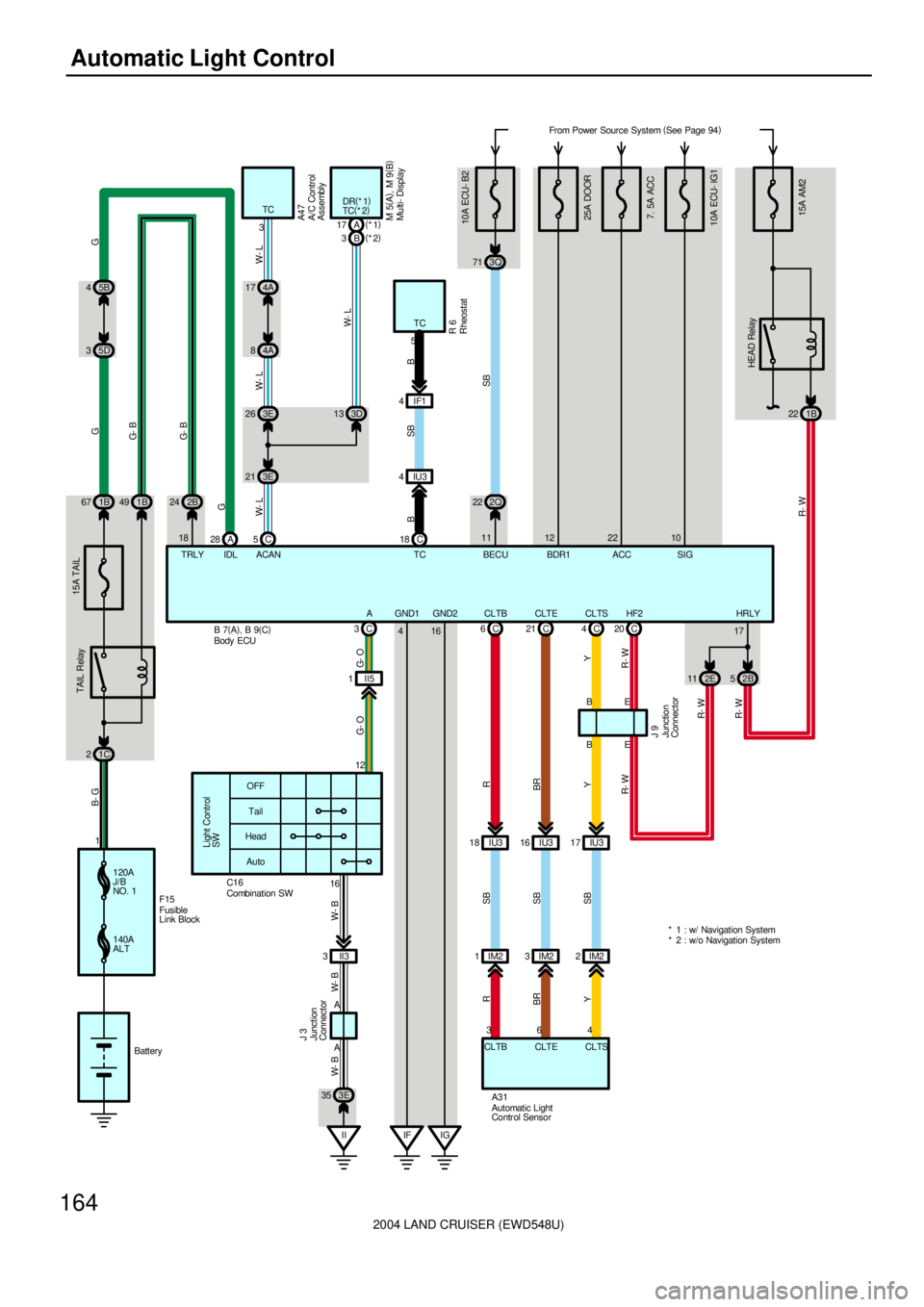
164Automatic Light Control
B 7(
A)
, B 9(
C) 5B 4
5D 3
15A AM2
From Power Source System (
See Page 94)
1C 2
TAIL Relay
G 15A TAIL
120A
J/B
NO. 1
140A
ALTF15
Battery 11B 67
A 28 2B 24 1B 49
HEAD Relay
22 1B
52B 11 2E C 20
HeadTail OFF
Light Control
SW
Auto
II3 316
A A
II 3E 35
J 3
W- B W- B W- B
C 3
II5 1
IU3 17 IU3 18 IU316 C 6C21 C4
CLTS CLTB CLTE4 36B
A31B
YSB SB
SB YR
BR
Y
CLTS CLTB CLTE
E
E C 53E 26
3E 213D 13 4A 17
4A 8A 17(
*1)
B 3(
*2)
10A ECU- IG17. 5A ACC B- G
G- B
G- B
G
W- LG
W- L W- L
W- L
IDL TRLY 183TCDR(
*1)
TC(
*2)
ACAN
A47
M 5(
A)
, M 9(
B)
R- W R- W R- WR- W R- W
17HRLY HF2
J 9G- O G- O
A
12
C16
10A ECU- B2
SB
2Q 223Q 71
11 22 10
SIG ACC BECU TCC 18 4IF1
IU3 4
BSB
TC
5R 6 B
* 2 : w/o Navigation System * 1 : w/ Navigation System
Automatic Light
Contr ol Sensor Combination SW
Multi- Display
RheostatA/C Control
Assembly
Body ECU
Junction
Connector Junction
Connector
Fusible
Link Block16 GND1 GND2
4
IG IF
BRR
25A DOOR
12
BDR1
IM2 1IM23IM22
Page 2173 of 3115
2004 LAND CRUISER (EWD548U)
166Light Auto Turn Off
B 7(
A)
, B 8(
B)
, B 9(
C) 5B 4
5D 3
15A AM2
1C 2
TAIL Relay
G 15A TAIL
120A
J/B
NO. 1
140A
ALTF15
Battery 11B 67
A 28 2B 24 1B 493
HEAD Relay
22 1B
52B 11 2E C 20
HeadTa il OFF
Light Control
SW
Auto
II3 316
A A
II 3E 35
J 3
W- B W- B W- B
C 8
II5 5
E
E
10A
ECU- IG1 7. 5A ACC B- G
G- B
G- B
GG
IDL TRL Y 18
R- W R- W R- WR- W R- W
17HRLY HF2
J 9G- B G- B
TAI L
14
C16
10A ECU- B2 SB
2Q 223Q 71
11 22 10
SIG ACC BECUFrom Power Source System (
See Page 94)
25A DOOR
12
BDR1
1 10 2K82EB 23
D14R- Y R- Y
DCTY
II5 2
13 HEAD
C 1
R- W R- W
Combination SW
Door Courtesy SW
Front LH
Body ECU
Junction
Connector Junction
Connector
Fusible Link
Block16 GND1 GND2
4
IG IF 2 23 3E 18 3EC 14
U 1R- B R- B
KSW
Unlock Warning SW
13P 33P
2E 18
W- B W- B
1
Page 2179 of 3115
2004 LAND CRUISER (EWD548U)
172Multiplex Communication System
120A
J/B
NO. 1
140A
ALTF15 From Power Source System (
See Page 94)
7. 5A
IDLE UP
2G 2B 7(
A)
, B 8(
B)
, B 9(
C)
A 27 A3
Battery15 232G 1
2K 92Q79
1 4
3
OFF
DOOR ON
BR1 8
BR1 9 BR1 11
F11
F1 0
G- W
B- G
SB
L- Y B- GR
R- W L- Y
SB
R
R W W- B
W
W W- BDOME Relay
DEF LMRY
W- B
R
G- W
B 7 B 7
B 7
IF 2L 11
W- B
2 1
1R 2L 8
25A DOOR12BDR1
Front Personal Light
Body ECU
Fr ont Interior Light
Rear Per sonal Light
Fusible Link Block
B
120A
MAIN 2B- G
B- G
Page 2181 of 3115
2004 LAND CRUISER (EWD548U)
174Multiplex Communication System
B- G
SB
L- YB 7(
A)
, B 8(
B)
, B 9(
C)
10A
DOME
3Q 17 3Q45 5B 4
5D 32B 24 A 28
2A 16
2Q 53 From Power Source System (
See Page 94)
1C 21B59 1B 49 1A 62 1A 64
15A
FR FOG
FR FOG RelayTAIL Relay
1B 67
EAR- L
SB
W- B
SB
L- Y IDL TRLY
G G
G- B
SB
R- B
R- B
G- B
G
B- G
G- Y SB W- B
18
SB
1 2
F 2 W- B
15A
TAI L
1 2
F 1 W- B
E15
W- BG- Y
LP
B 6
G- Y
Front Fog Light LH
Front Fog Light RH
Body ECU
1A 61
B- G
B- G
Page 2182 of 3115
2004 LAND CRUISER (EWD548U)
175
B 7(
A)
, B 8(
B)
, B 9(
C)
10A
HEAD
LH- LWR
1A 1912 1A20A
HEAD
LH- UPR 10A
HEAD
RH- LWR
1A 91B22 1B102B 72G 9
1A 26
1 2
1 2
1 2
24 1A
30 1AA 7DRL
R- L
SB
W- B
SB
L- YW- B
R- W
SB
R- B
W- B
SB
L- Y
W- B R- L
R- B R- B W- B
R- G R- W
W- B W- B
R- Y R- Y H 2
H 4
H 1HEAD Relay
HEAD HI Relay
R- B
E 1
W- B E 220A
HEAD
RH- UPR
1A 8
R- WR- W Headlight LH
(
High) Headlight LH
(
Low)
Headlight RH
(
Low)
Body ECU
1C 1
B- G
R- L
B- G
Page 2183 of 3115
2004 LAND CRUISER (EWD548U)
176Multiplex Communication System
B 7(
A)
, B 8(
B)
, B 9(
C)
W- B
R- W
SB
R- B
W- B
SB
L- Y2B 52E11 17HRLY
C 20
A 5A1B4B2
1 2B 1
1B 131A 22 D 2(
A)
, D 3(
B) J 9
EE R- W R- WC 1C8C3C7
D D
II5 3 II5 1 II5 2
J 9 H 3
II5 5
G- O
G- B
R- W
SB
R- Y
W- B
W- B
R- Y
W- B
W- B
W- B
R- Y
R- W
G- B
G- O
R- B R- B R- BG- OG- B R- W R- Y
W- B
R- Y
W- B
W- B
HF2
W- B W- B
L- YSB
R- W
HEAD TAIL A HF
E 2E 2E 2
E 1
SB A3A 2B3
E 1
R- Y
R- W
R- W
W- BDaytime Running
Light Relay
No. 3
Headlight RH (
High)
Body ECU
Junction Connector
Junction
Connector
R- B
Page 2185 of 3115
2004 LAND CRUISER (EWD548U)
178Multiplex Communication System
B 7(
A)
, B 8(
B)
, B 9(
C)
W- B
SB
R- Y
SB
L- Y10A
HORN
1B 21
2B 9
2Q 24C CT 5
2Q 26
2Q 22 2I2 IL3 12 IL322 IL36 10A
ECU- B2 From Power Source System
(
See Page 94)
3Q 44 3Q71
IF 2Q 20
2E18LP(
*1) B 14(
*2) A 21(
*1)
A 3(
*1)
B 8(
*2) 3Q 76
3D 12IL3 5IL320
3Q 73
3E 13
4D 14
4D 5
J14
M 5(
A)
, M 9(
B)
3E 20
3E 12
7B 7
7B 8
9
7
HORN Relay
C 17
D 7
OBD2
+B2 E HORN IND REV
329525 23
SB G- O SB
SB
B
W- B
G- O
G- R
B SBV- W V- W V- W
SB
L- W
SB
SB
SB B G- RSB
W- B
B
V- WL- W
SB
TAC
SIL
L- YSB R- YSB
W- B W- B
SB SB
11BECU
SECURITY(
*2)
GND(
*2) GN D1(
*1)
GN D1(
*1)
Data Link
Connector 3Multi- Display
Theft Deterrent ECU Body ECU
Junction
Connector
Page 2204 of 3115

2004 LAND CRUISER (EWD548U)
197
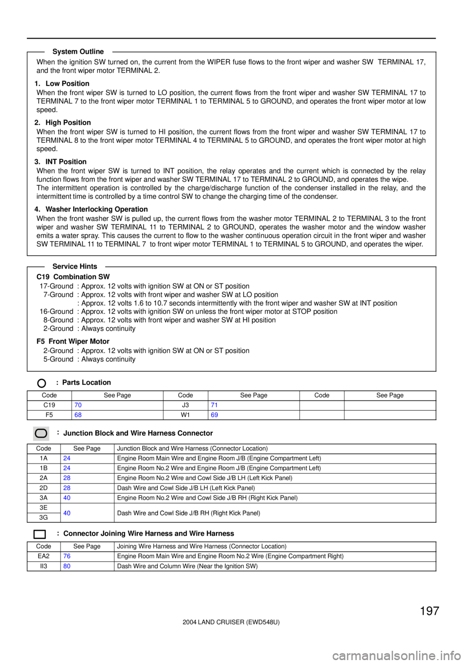
When the ignition SW turned on, the current from the WIPER fuse flows to the front wiper and washer SW TERMINAL 17,
and the front wiper motor TERMINAL 2.
1. Low Position
When the front wiper SW is turned to LO position, the current flows from the front wiper and washer SW TERMINAL 17 to
TERMINAL 7 to the front wiper motor TERMINAL 1 to TERMINAL 5 to GROUND, and operates the front wiper motor at low
speed.
2. High Position
When the front wiper SW is turned to HI position, the current flows from the front wiper and washer SW TERMINAL 17 to
TERMINAL 8 to the front wiper motor TERMINAL 4 to TERMINAL 5 to GROUND, and operates the front wiper motor at high
speed.
3. INT Position
When the front wiper SW is turned to INT position, the relay operates and the current which is connected by the relay
function flows from the front wiper and washer SW TERMINAL 17 to TERMINAL 2 to GROUND, and operates the wipe.
The intermittent operation is controlled by the charge/discharge function of the condenser installed in the relay, and the
intermittent time is controlled by a time control SW to change the charging time of the condenser.
4. Washer Interlocking Operation
When the front washer SW is pulled up, the current flows from the washer motor TERMINAL 2 to TERMINAL 3 to the front
wiper and washer SW TERMINAL 11 to TERMINAL 2 to GROUND, operates the washer motor and the window washer
emits a water spray. This causes the current to flow to the washer continuous operation circuit in the front wiper and washer
SW TERMINAL 11 to TERMINAL 7 to front wiper motor TERMINAL 1 to TERMINAL 5 to GROUND, and operates the wiper.
C19 Combination SW
17-Ground : Approx. 12 volts with ignition SW at ON or ST position
7-Ground : Approx. 12 volts with front wiper and washer SW at LO position
: Approx. 12 volts 1.6 to 10.7 seconds intermittently with the front wiper and washer SW at INT position
16-Ground : Approx. 12 volts with ignition SW on unless the front wiper motor at STOP position
8-Ground : Approx. 12 volts with front wiper and washer SW at HI position
2-Ground : Always continuity
F5 Front Wiper Motor
2-Ground : Approx. 12 volts with ignition SW at ON or ST position
5-Ground : Always continuity
: Parts Location
CodeSee PageCodeSee PageCodeSee Page
C1970J371
F568W169
:Junction Block and Wire Harness Connector
CodeSee PageJunction Block and Wire Harness (Connector Location)
1A24Engine Room Main Wire and Engine Room J/B (Engine Compartment Left)
1B24Engine Room No.2 Wire and Engine Room J/B (Engine Compartment Left)
2A28Engine Room No.2 Wire and Cowl Side J/B LH (Left Kick Panel)
2D28Dash Wire and Cowl Side J/B LH (Left Kick Panel)
3A40Engine Room No.2 Wire and Cowl Side J/B RH (Right Kick Panel)
3E40Dash Wire and Cowl Side J/B RH (Right Kick Panel)3G40Dash Wire and Cowl Side J/B RH (Right Kick Panel)
:Connector Joining Wire Harness and Wire Harness
CodeSee PageJoining Wire Harness and Wire Harness (Connector Location)
EA276Engine Room Main Wire and Engine Room No.2 Wire (Engine Compartment Right)
II380Dash Wire and Column Wire (Near the Ignition SW)
System Outline
Service Hints