Page 230 of 3115
BE0GS-19
I24745
Mirror Assenbly
� Mirror Heater
Rear Window Defogger
Cowl Side J/B LH
� DEFOG Fuse
� DEFOG Relay
Ignition Switch Integration Control Panel Assembly
� Defogger Switch
� Mirror Heater Switch Engine Room R/B
� MIR HTR Fuse
� MIR HTR Relay
BE-74
- BODY ELECTRICALDEFOGGER SYSTEM
2447 Author�: Date�:
2004 LAND CRUISER (RM1071U)
DEFOGGER SYSTEM
LOCATION
Page 231 of 3115

INSPECTION
1. INSPECT D")
BE2EE-01
I25790
w/o Navigation System:
w/ Navigation System:
ABC
I01200
2 1
35
2 5
1 3
- BODY ELECTRICALDEFOGGER SYSTEM
BE-75
2448 Author�: Date�:
2004 LAND CRUISER (RM1071U)
INSPECTION
1. INSPECT DEFOGGER SWITCH CIRCUIT
Disconnect the connector from the panel switch and inspect the
connector on wire harness side, as shown in the chart.
w/ Navigation:
Tester connectionConditionSpecified condition
B12 (GND) - GroundConstantContinuity
B11 (+B) - GroundConstantBattery positive voltage
B22 (IG) - GroundIgnition switch LOCK or ACCNo voltage
B22 (IG) - GroundIgnition switch ONBattery positive voltage
A10 (RDFGR) - GroundConstantBattery positive voltage
w/o Navigation:
Tester connectionConditionSpecified condition
16 (GND) - GroundConstantContinuity
8 (IG) - GroundIgnition switch LOCK or ACCNo voltage
8 (IG) - GroundIgnition switch ONBattery positive voltage
2 (DEFC) - GroundConstantBattery positive voltage
If the circuit is not as specified, replace the switch.
2. INSPECT DEFOGGER RELAY CONTINUITY
ConditionTester connectionSpecified condition
Constant1 - 2Continuity
Apply B+ between
terminals 1 and 2.3 - 5Continuity
If continuity is not as specified, replace the relay.
Page 232 of 3115

I25040
Built in relayExcept built in relay
I01291
Tester Probe
Tin FoilHeat Wire
I01292
At Center
I01293
0 Volts
Broken
WireSeveral
Volts
Battery
side Ground sideFoil strip
� � BE-76
- BODY ELECTRICALDEFOGGER SYSTEM
2449 Author�: Date�:
2004 LAND CRUISER (RM1071U)
3. INSPECT ENGINE ROOM R/B RELAY CIRCUIT (See
Pase BE-15)
HINT:
The mirror heater relay is built in engine room junction block.
Also the relay is constructed with a relay block that is in the junc-
tion block as a unit. To disconnect the wire harness connecting
with relay block is impossible. If the relay has a malfunction, re-
place it with junction block assembly wire harness together.
4. INSPECT DEFOGGER WIRE
NOTICE:
�When cleaning the glass, use a soft, dry cloth, and wipe the
glass in the direction of the wire. Take care not to damage
the wires.
�Do not use detergents or glass cleaners with abrasive in-
gredients.
�When measuring voltage, wrap a piece of tin foil around the
tip of the negative probe and press the foil against the wire
with your finger, as shown.
(a) Turn the ignition switch ON.
(b) Turn the defogger switch ON.
(c) Inspect the voltage at the center of each heat wire, as
shown.
VoltageCriteria
Approx. 5VOkay (No break in wire)
Approx. 10V or 0VBroken wire
HINT:
If there is approximately 10 V, the wire is broken between the
center of the wire and the positive (+) end. If there is no voltage,
the wire is broken between the center of the wire and ground.
(d) Place the voltmeter positive (+) lead against the defogger
wire on the battery side.
(e) Place the voltmeter negative (-) lead with the foil strip
against the wire on the ground side.
(f) Slide the positive (+) lead from battery to ground side.
(g) The point where the voltmeter deflects from several V to
zero V is the place where the defogger wire is broken.
HINT:
If the heat wire is not broken, the voltmeter indicates 0 V at the
positive (+) end of the heat wire but voltage gradually increases
to about 12 V as the meter probe moves to the other end.
Page 234 of 3115
BE0GS-19
I24745
Mirror Assenbly
� Mirror Heater
Rear Window Defogger
Cowl Side J/B LH
� DEFOG Fuse
� DEFOG Relay
Ignition Switch Integration Control Panel Assembly
� Defogger Switch
� Mirror Heater Switch Engine Room R/B
� MIR HTR Fuse
� MIR HTR Relay
BE-74
- BODY ELECTRICALDEFOGGER SYSTEM
2447 Author�: Date�:
2004 LAND CRUISER (RM1071U)
DEFOGGER SYSTEM
LOCATION
Page 236 of 3115
BE02Q-23
I25526 I06215
ECM Transponder Key CoilEngine Room R/B
� EFI Fuse
� EFI and ECD Relay
DLC3
Transponder Key Amplifier
Passenger Side Junction Block
� IGN Fuse
- BODY ELECTRICALENGINE IMMOBILISER SYSTEM
BE-195
2568 Author�: Date�:
2004 LAND CRUISER (RM1071U)
LOCATION
Page 242 of 3115
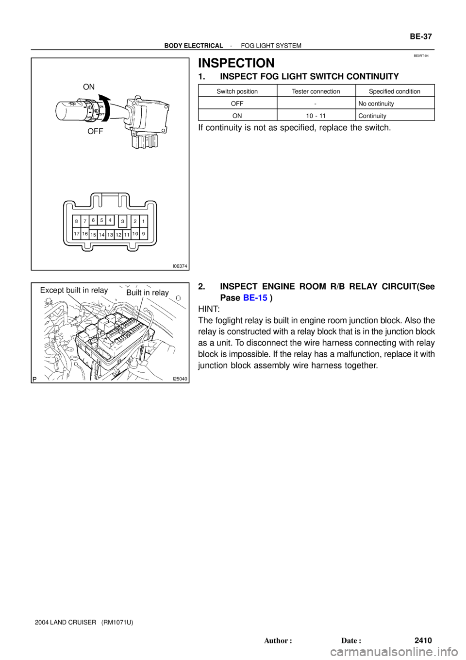
BE0RT-04
I06374
ON
OFF
I25040
Built in relayExcept built in relay
- BODY ELECTRICALFOG LIGHT SYSTEM
BE-37
2410 Author�: Date�:
2004 LAND CRUISER (RM1071U)
INSPECTION
1. INSPECT FOG LIGHT SWITCH CONTINUITY
Switch positionTester connectionSpecified condition
OFF-No continuity
ON10 - 11Continuity
If continuity is not as specified, replace the switch.
2. INSPECT ENGINE ROOM R/B RELAY CIRCUIT(See
Pase BE-15)
HINT:
The foglight relay is built in engine room junction block. Also the
relay is constructed with a relay block that is in the junction block
as a unit. To disconnect the wire harness connecting with relay
block is impossible. If the relay has a malfunction, replace it with
junction block assembly wire harness together.
Page 243 of 3115
BE0H2-16
I24736
Front Fog Light
Combination Switch
� Front Fog Light Switch
Engine Room R/B
� FR FOG Relay
� FR FOG Fuse
BE-36
- BODY ELECTRICALFOG LIGHT SYSTEM
2409 Author�: Date�:
2004 LAND CRUISER (RM1071U)
FOG LIGHT SYSTEM
LOCATION
Page 252 of 3115

I06426
HI
Flash OFFTAIL HEAD AUTO
LO
BE2EH-01
I04036
1 2
3 41 2 3
4 5 6 Connector ºBº Connector ºAº
A2 B3 B1
A3
A5 A1 B4 B2 BE-32
- BODY ELECTRICALHEADLIGHT AND TAILLIGHT SYSTEM
2405 Author�: Date�:
2004 LAND CRUISER (RM1071U)
INSPECTION
1. INSPECT LIGHT CONTROL SWITCH CONTINUITY
Switch positionTester connectionSpecified condition
OFF-No continuity
TAIL14 - 16Continuity
HEAD13 - 14 - 16Continuity
AUTO12 - 16Continuity
If continuity is not as specified, replace the switch.
2. INSPECT HEADLIGHT DIMMER SWITCH CONTINU-
ITY
Switch positionTester connectionSpecified condition
Low beam16 - 17Continuity
High beam7 - 16Continuity
Flash7 - 8 - 16Continuity
If continuity is not as specified, replace the switch.
3. INSPECT DAYTIME RUNNING LIGHT NO.3 AND NO.4
RELAY CONTINUITY
Tester connectionConditionSpecified condition
A1 - B3ConstantContinuity
A3 - A5ConstantContinuity
B3 - B4ConstantContinuity
A2 - A5Apply battery positive voltage between
terminals A1 and B3.Continuity
B1 - B2Apply battery positive voltage between
terminals B3 and B4.Continuity
If continuity is not as specified, replace the relay.