Page 288 of 3115
BE2EJ-01
I25272
Engine Room R/B:
HTR RelayABS MTR1 Relay
ABS MTR2 RelayC/OPN Relay
ABS SOL RelayF/PUMP Relay
EFI OR ECD RelaySTARTER Relay
- BODY ELECTRICALPOWER SOURCE
BE-15
2388 Author�: Date�:
2004 LAND CRUISER (RM1071U)
INSPECTION
1. INSPECT ENGINE ROOM R/B CIRCUIT
Page 292 of 3115

- BODY ELECTRICALPOWER SOURCE
BE-19
2392 Author�: Date�:
2004 LAND CRUISER (RM1071U)
(a) Remove the fuse from the junction block and inspect the
connector on junction block side.
Fuse Tester connectionConditionSpecified condition
TOWING 1 - GroundConstantBattery positive voltage
MIR HTR 3 - GroundConstantBattery positive voltage
RR HTR 5 - GroundConstantBattery positive voltage
HAZ-TRN 7 - GroundConstantBattery positive voltage
ALT-S 9 - GroundConstantBattery positive voltage
NV-IR 13 - GroundConstantBattery positive voltage
FR FOG 13 - GroundConstantBattery positive voltage
BRK CTRL 15 - GroundConstantBattery positive voltage
HEAD CLNER 17 - GroundIgnition switch ONBattery positive voltage
FR-IG 19 - GroundIgnition switch ONBattery positive voltage
PANEL 21 - GroundLight control switch HEAD or TAILBattery positive voltage
TOWING TAIL 23 - GroundLight control switch HEAD or TAILBattery positive voltage
TAIL 25 - GroundLight control switch HEAD or TAILBattery positive voltage
BAT 29 - GroundConstantBattery positive voltage
TEL 31 - GroundConstantBattery positive voltage
AMP 33 - GroundConstantBattery positive voltage
EFI or ECD NO.1 35 - GroundConstantBattery positive voltage
AM2 37 - GroundConstantBattery positive voltage
ETCS 39 - GroundConstantBattery positive voltage
HORN 41 - GroundConstantBattery positive voltage
HEAD LH-UPR 51 - GroundLight control switch HI or FlashBattery positive voltage
HEAD RH-UPR 49 - GroundLight control switch HI or FlashBattery positive voltage
HEAD LH-LWR 47 - GroundLight control switch HEADBattery positive voltage
HEAD RH-LWR 45 - GroundLight control switch HEADBattery positive voltage
ST1 1 - GroundConstantBattery positive voltage
AHC 1 - GroundConstantBattery positive voltage
ABS NO.1 1 - GroundConstantBattery positive voltage
ABS NO.2 1 - GroundConstantBattery positive voltage
STARTER 1 - GroundConstantBattery positive voltage
If the circuit is not as specified, inspect the circuits connected
to other parts.
(b) Remove the relay from the junction block and inspect the
connector on junction block side.
Relay Tester connectionConditionSpecified condition
AHC 1 - GroundIgnition switch ONBattery positive voltage
ABS SOL 1 - GroundIgnition switch ONBattery positive voltage
ABS MTR1 1 - GroundConstantBattery positive voltage
ABS MTR2 1 - GroundIgnition switch ONBattery positive voltage
STARTER 5 - GroundConstantContinuity
STARTER 2 - GroundIgnition switch ONBattery positive voltage
EFI or ECD 3 - GroundConstantBattery positive voltage
C/OPN SPIL VLV 5 - GroundConstantBattery positive voltage
C/OPN SPIL VLV 2 - GroundIgnition switch ONContinuity
Page 302 of 3115
I24921
Fuses:
1. TOWING
2. MIR HTR
3. RR HTR
4. HAZ-TEN
5. ALT-S
6. NV-IR
7. FR FOG
8. TOWING BRK
9. HEAD CLNER
10. FR-IG
11. PANEL
12. TOWING TAIL
13. TAIL
14. -
15. BAT
16. TEL
17. AMP
18. EFI or ECD NO.1
19. AM2
20. ETCS
21. HORN
22. HEAD RH-LWR
23. HEAD LH-LWR
24. HEAD RH-UPR
25. HEAD LH-UPR
26.STARTER
27. GLOW
28. ST1
29. AHC
30. ABS NO.1
31. ABS NO.2
Relays:
A. AHC
B. ABS SOL
C. ABS MTR1
D. ABS MTR2
E. STARTER
F. EFI or ECD
G. C/OPN
H. F/PUMP
I. HTR
J. IG1 NO.1
K. MIR HTR
L. RR HTR
M. FR FOG
N. TAIL
O. PANEL
P. CDS FAN
Q. MG CLT
R. W/TEMP CUT
S. HEAD
T. HEAD HI
U. HORN
A
1
B CD
E F
G
H I
J
KL
MN O
P
RST
U Q
2 3 4 5 6 7 8 9 10 11 12 13
14 15 16 17 18 19 20 21 22 23 24 25 26
2728 29 30 31
Engine Room R/B BE-12
- BODY ELECTRICALPOWER SOURCE
2385 Author�: Date�:
2004 LAND CRUISER (RM1071U)
Page 339 of 3115

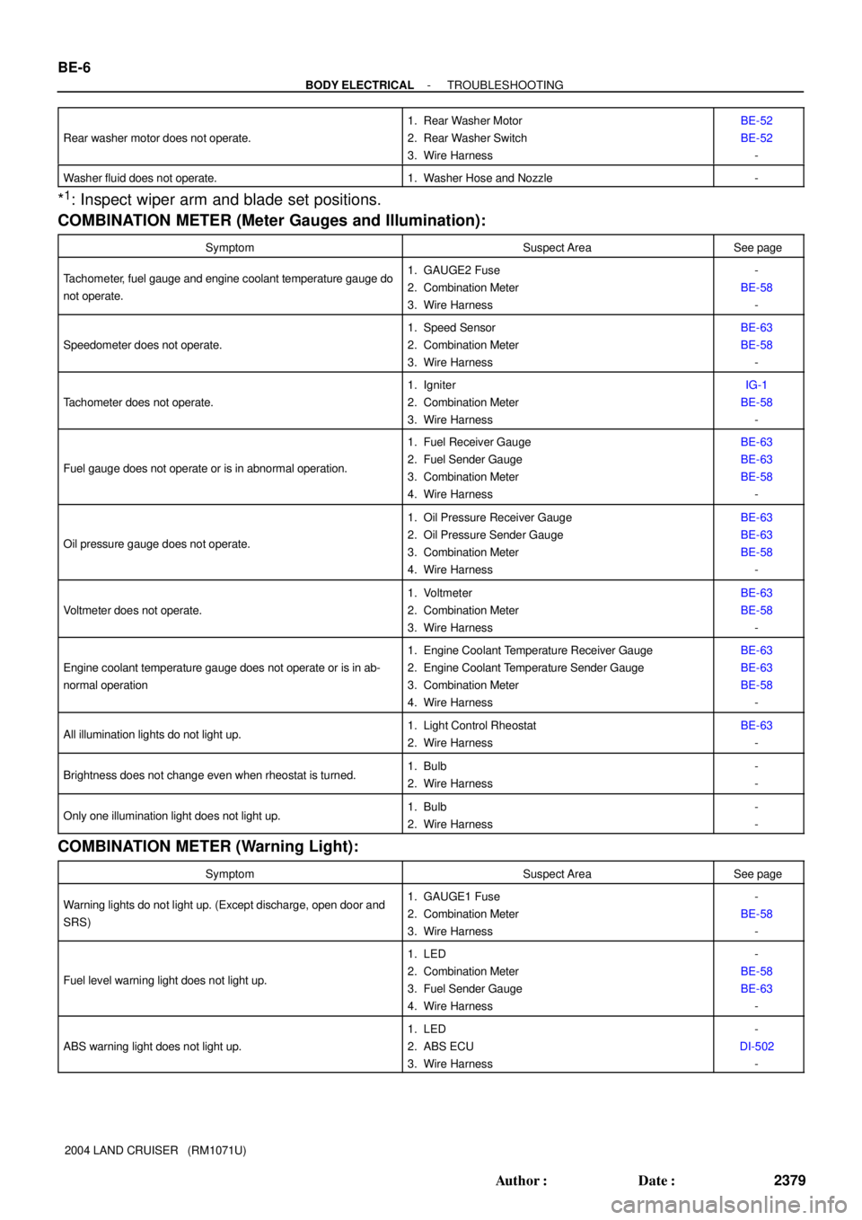
BE-6
- BODY ELECTRICALTROUBLESHOOTING
2379 Author�: Date�:
2004 LAND CRUISER (RM1071U) Rear washer motor does not operate.
1. Rear Washer Motor
2. Rear Washer Switch
3. Wire HarnessBE-52
BE-52
-
Washer fluid does not operate.1. Washer Hose and Nozzle-
*1: Inspect wiper arm and blade set positions.
COMBINATION METER (Meter Gauges and Illumination):
SymptomSuspect AreaSee page
Tachometer, fuel gauge and engine coolant temperature gauge do
not operate.1. GAUGE2 Fuse
2. Combination Meter
3. Wire Harness-
BE-58
-
Speedometer does not operate.
1. Speed Sensor
2. Combination Meter
3. Wire HarnessBE-63
BE-58
-
Tachometer does not operate.
1. Igniter
2. Combination Meter
3. Wire HarnessIG-1
BE-58
-
Fuel gauge does not operate or is in abnormal operation.
1. Fuel Receiver Gauge
2. Fuel Sender Gauge
3. Combination Meter
4. Wire HarnessBE-63
BE-63
BE-58
-
Oil pressure gauge does not operate.
1. Oil Pressure Receiver Gauge
2. Oil Pressure Sender Gauge
3. Combination Meter
4. Wire HarnessBE-63
BE-63
BE-58
-
Voltmeter does not operate.
1. Voltmeter
2. Combination Meter
3. Wire HarnessBE-63
BE-58
-
Engine coolant temperature gauge does not operate or is in ab-
normal operation
1. Engine Coolant Temperature Receiver Gauge
2. Engine Coolant Temperature Sender Gauge
3. Combination Meter
4. Wire HarnessBE-63
BE-63
BE-58
-
All illumination lights do not light up.1. Light Control Rheostat
2. Wire HarnessBE-63
-
Brightness does not change even when rheostat is turned.1. Bulb
2. Wire Harness-
-
Only one illumination light does not light up.1. Bulb
2. Wire Harness-
-
COMBINATION METER (Warning Light):
SymptomSuspect AreaSee page
Warning lights do not light up. (Except discharge, open door and
SRS)1. GAUGE1 Fuse
2. Combination Meter
3. Wire Harness-
BE-58
-
Fuel level warning light does not light up.
1. LED
2. Combination Meter
3. Fuel Sender Gauge
4. Wire Harness-
BE-58
BE-63
-
ABS warning light does not light up.
1. LED
2. ABS ECU
3. Wire Harness-
DI-502
-
Page 379 of 3115
BO1J6-03
H18901
Energy Absorber
Fog LightRadiator Grille
: Specified torque
N´m (kgf´cm, ft´lbf)
3.0 (31, 27 in.´lbf)
Front Bumper Cover
x 4
58 (590, 43)
58 (590, 43)
58 (590, 43)
8.5 (87, 76 in.´lbf)
3.0 (31, 27 in.´lbf)
4.9 (50, 43 in.´lbf)
4.9 (50, 43 in.´lbf)
Front Bumper Reinforcement
58 (590, 43)
Fog Light BO-4
- BODYFRONT BUMPER
2578 Author�: Date�:
2004 LAND CRUISER (RM1071U)
FRONT BUMPER
COMPONENTS
Page 520 of 3115

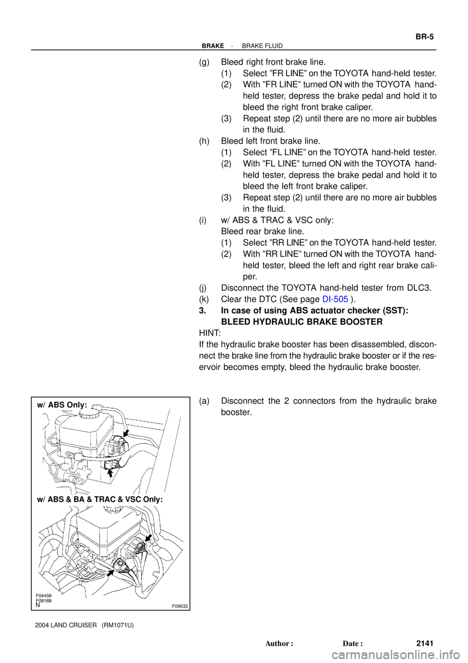
F04459F09169F09632
w/ ABS Only:
w/ ABS & BA & TRAC & VSC Only:
- BRAKEBRAKE FLUID
BR-5
2141 Author�: Date�:
2004 LAND CRUISER (RM1071U)
(g) Bleed right front brake line.
(1) Select ºFR LINEº on the TOYOTA hand-held tester.
(2) With ºFR LINEº turned ON with the TOYOTA hand-
held tester, depress the brake pedal and hold it to
bleed the right front brake caliper.
(3) Repeat step (2) until there are no more air bubbles
in the fluid.
(h) Bleed left front brake line.
(1) Select ºFL LINEº on the TOYOTA hand-held tester.
(2) With ºFL LINEº turned ON with the TOYOTA hand-
held tester, depress the brake pedal and hold it to
bleed the left front brake caliper.
(3) Repeat step (2) until there are no more air bubbles
in the fluid.
(i) w/ ABS & TRAC & VSC only:
Bleed rear brake line.
(1) Select ºRR LINEº on the TOYOTA hand-held tester.
(2) With ºRR LINEº turned ON with the TOYOTA hand-
held tester, bleed the left and right rear brake cali-
per.
(j) Disconnect the TOYOTA hand-held tester from DLC3.
(k) Clear the DTC (See page DI-505).
3. In case of using ABS actuator checker (SST):
BLEED HYDRAULIC BRAKE BOOSTER
HINT:
If the hydraulic brake booster has been disassembled, discon-
nect the brake line from the hydraulic brake booster or if the res-
ervoir becomes empty, bleed the hydraulic brake booster.
(a) Disconnect the 2 connectors from the hydraulic brake
booster.
Page 522 of 3115

F02823
F02824
F02825
- BRAKEBRAKE FLUID
BR-7
2143 Author�: Date�:
2004 LAND CRUISER (RM1071U)
(i) Bleed right front brake line.
(1) Turn the selector switch of the actuator checker to
the ºFRONT RHº position.
(2) Push and hold in MAIN push switch, depress the
brake pedal and hold it to bleed the right front brake
caliper.
NOTICE:
Do not keep the MAIN switch pushed in for more than 10
sec. When operating it continuously, set the interval of
more than 20 sec.
(3) Repeat step (2) until there are no more air bubbles
in the fluid.
(j) Bleed left front brake line.
(1) Turn the selector switch of the actuator checker to
the ºFRONT LHº position.
(2) Push and hold in the MAIN push switch, depress the
brake pedal and hold it to bleed the left front brake
caliper.
NOTICE:
Do not keep the MAIN switch pushed in for more than 10
sec. When operating it continuously, set the interval of
more than 20 sec.
(3) Repeat step (2) until there are no more air bubbles
in the fluid.
(k) w/ ABS & TRAC & VSC only:
Bleed right rear brake line.
(1) Push and hold in the ºSUB LHº and ºSUB RHº
switches, bleed the right rear brake caliper.
NOTICE:
Do not keep the MAIN switch pushed in for more than 10
sec. When operating it continuously, set the interval of
more than 20 sec.
(2) Repeat step (1) until there are no more air bubbles
in the fluid.
Page 524 of 3115
BR0X9-02
F08309
Pedal Pad Brake PedalReturn Spring
Cowl Side TrimLower No. 1 PanelLH Lower Panel
No. 2 Heater to Register Duct
ABS ECU or
ABS & BA & TRAC
& VSC ECU
N´m (kgf´cm, ft´lbf): Specified torque
Cushion
Stop Light Switch
20 (200, 14)
Hydraulic Brake Booster Assembly
MP Grease
Front Door Scuff Plate
5.0 (51, 44 in.´lbf)
Clevis PinClip
- BRAKEBRAKE PEDAL
BR-1 1
2147 Author�: Date�:
2004 LAND CRUISER (RM1071U)
COMPONENTS