Page 1277 of 1463
MANUAL & SEMIAUTO-HVAC 7B/C-3
Application
Type
Expansion Valve
Resistance
Thermo AmpDescription
Tank laminated
Uniform external pressure type (1.5 RT)
4 stage (Coil resistance)
Sensor type OFF : 2±0.5°C, DIFF : 2±0.5°C
EVAPORATOR
Application
Heater Core Type
Heating Capacity
Heater Core Size (LxWxT)Description
2-ROW
4,600 kcal/h (AT 300 CMH)
219.5 x 151.8 x 52.0
HEATER UNIT
Application
Condenser Bolt
Condenser Fan Nut
Condenser Bolt
Receiver Drier Pipe Bolt
Receiver Drier Pipe Bolt (Condenser)
Pressure Pipe Bolt
Pressure Mounting BoltNlm
4-6
4-6
4-6
5-8
4-6
20-30
20-26
FASTENER TIGHTENING SPECIFICATIONS
Page 1313 of 1463
SUPPLEMENTAL RESTRAINT SYSTEM(SRS) 8B-9
Diagnosis
Air bag control unit diagnoses each function in the intervals of 250ms - 20 sec. during start-up or driving to prevent
unwanted air bag deployment. If there is defect, it turns on or blinks warning lamp to indicate defects in the air bag
system to the driver. And fatal defect is found, air bag control unit enters overall or partial shutdown status and fault
code will be stored.
Air bag control unit diagnoses following items.
- Ignition TR
- Acceleration
- Microprocessor, RAM and ROM
- Watchdog
- Shutdown Switch
Diagnosis Condition Diagnosis Items
Start-up (ignition ON)
During Driving
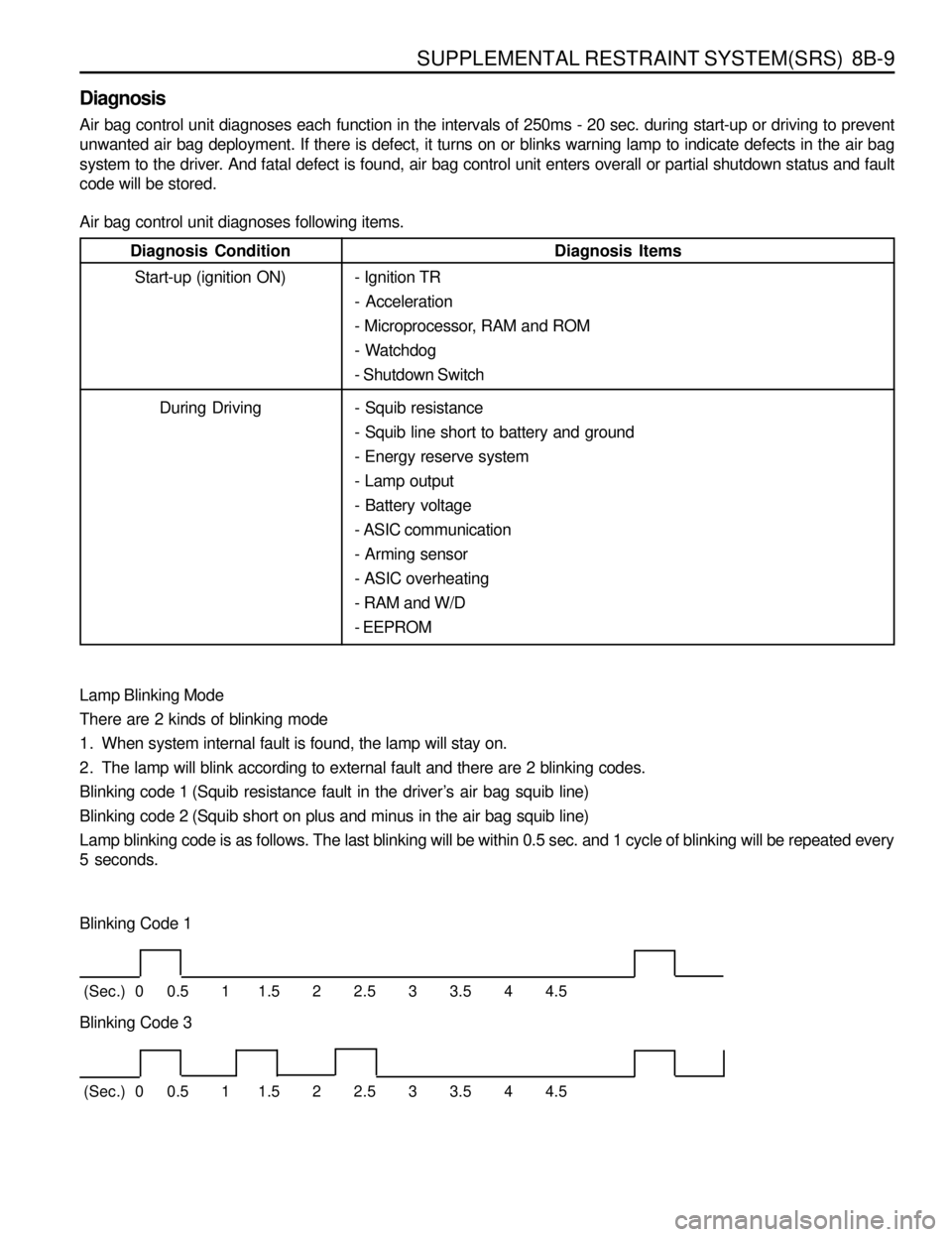
Lamp Blinking Mode
There are 2 kinds of blinking mode
1. When system internal fault is found, the lamp will stay on.
2. The lamp will blink according to external fault and there are 2 blinking codes.
Blinking code 1 (Squib resistance fault in the driver’s air bag squib line)
Blinking code 2 (Squib short on plus and minus in the air bag squib line)
Lamp blinking code is as follows. The last blinking will be within 0.5 sec. and 1 cycle of blinking will be repeated every
5 seconds.
Blinking Code 1
(Sec.) 0 0.5 1 1.5 2 2.5 3 3.5 4 4.5
Blinking Code 3
(Sec.) 0 0.5 1 1.5 2 2.5 3 3.5 4 4.5
- Squib resistance
- Squib line short to battery and ground
- Energy reserve system
- Lamp output
- Battery voltage
- ASIC communication
- Arming sensor
- ASIC overheating
- RAM and W/D
- EEPROM
Page 1337 of 1463

BODY WIRING SYSTEM 9A-11
ENGINE ROOM
1 Engine Room Relay Box
1.1 Main Wiring Connector
1.2 Main Wiring Connector
1.3 Main Wiring Connector........................................Gasoline E/G
1.4 Joint
1.5 Compressor, Condenser Fan Relay.....................Diesel E/G
1.6 Condenser Fan Relay 2
1.7 Air Conditioner Relay
1.8 Resistor with Diode..............................................Gasoline E/G
1.9 Front Fog Lamp Relay
1.10 Condenser Fan Relay 1
1.11 Tail Lamp Relay
1.12 Horn Relay
2 Octane Selector...................................................Gasoline E/G with HFM
3 Preheating Unit....................................................Diesel E/G
4 Preheating Timer Unit..........................................Diesel E/G
5 ECS Main Wiring Connector................................ ECS
6 Brake Leveling Fluid Sensor
7 ABD Main Wiring Connector................................ABD 5.0
7-1 ABS Main Wiring Connector................................ABD 5.0
8 ABD main Wiring Connector................................ABD 5.0
9 Engine Temperature Sensor................................Diesel E/G
10 ABS 5.0 ECU.......................................................ABS 5.0
10-1ABD 5.0 Modulator...............................................ABD 5.0
11 Front Washer Motor.............................................Diesel E/G
12 Head Lamp Relay
13 Compressor .........................................................Air Conditioner
14 Wheel Speed Sensor...........................................ABS 5.0 or ABD 5.0
Page 1348 of 1463
9A-22 BODY WIRING SYSTEM
DIESEL ENGINE
1 Preheating Unit
2 Main Wiring Connector
3 Glow Plug 1
4 Glow Plug 25 Glow Plug 3
6 Glow Plug 4
7 Glow Plug 5
8 Water Temperature Sensor (Gauge)
Page 1376 of 1463
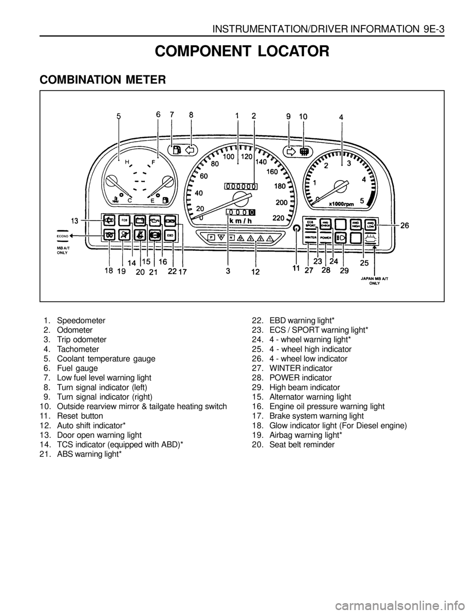
INSTRUMENTATION/DRIVER INFORMATION 9E-3
COMBINATION METER
COMPONENT LOCATOR
1. Speedometer
2. Odometer
3. Trip odometer
4. Tachometer
5. Coolant temperature gauge
6. Fuel gauge
7. Low fuel level warning light
8. Turn signal indicator (left)
9. Turn signal indicator (right)
10. Outside rearview mirror & tailgate heating switch
11. Reset button
12. Auto shift indicator*
13. Door open warning light
14. TCS indicator (equipped with ABD)*
21. ABS warning light*22. EBD warning light*
23. ECS / SPORT warning light*
24. 4 - wheel warning light*
25. 4 - wheel high indicator
26. 4 - wheel low indicator
27. WINTER indicator
28. POWER indicator
29. High beam indicator
15. Alternator warning light
16. Engine oil pressure warning light
17. Brake system warning light
18. Glow indicator light (For Diesel engine)
19. Airbag warning light*
20. Seat belt reminder
Page 1399 of 1463
GLASS AND MIRRORS 9L-9
TAILGATE GLASS
1 Wiper Arm and Blade Assembly
2 Heating Lines3 Tailgate Trim
4 Tailgate Glass
Notice
Removal and installation is as shown in upper drawings.