Page 584 of 1463

1F1-14 M162 ENGINE CONTROLS
Failure
codeItemChecking method Test
stepRequirementSpecified
valuePossible cause
Þ 9.0· Keep the engine run
above 2 minutes in
over 80°C of coolant
temperature.6.0 - 7.0 V· ECU
· Cable
· Oxygen sensor
· ·· ·
· Oxygen
sensor:
- Signal80,
81,
82,
83,
89,560
Þ 8.0· Engine:in cranking or
idle
560· Cable
· ECU
· ·· ·
· ECU:
- RPM signal
output32,
33,refer to figure
2
Þ 10.0· Keep the engine run
above 2 minutes in
over 80°C of coolant
temperature.· ·· ·
· Oxygen
sensor:
- Heating
function
operated
Þ 11.0· ·· ·
· No.1
cylinder
injector:
- Operating &
injection
time· When the coolant
temperature is
approx. 20°C:
- Engine:in cranking8.0 ms· Cable
· ECU
· No.1 Injector
· Coolant
temperature sensor
· Oxygen sensor
· Intake air
temperature sensor
- Voltage· Engine:in cranking
or idle
(above 5V in idling)
16 17
59
911
· Ignition:ON11 - 14 V
· ECU
· Cable
· Oxygen sensor
- Current
consumption0.2 - 2.0 A
72,
73,
63 11
· When the coolant
temperature is
approx. 80°C:
- Engine:at idling
speed
- Engine:at sharp
acceleration(full
throttle)
(refer to figure 3 and
4)approx.
2.7 - 5.0ms
approx.
14ms There will be a
voltage
fluctuation in
the range of
- 0.2 -1.0V
85,
86,
87,
Page 607 of 1463
M162 ENGINE CONTROLS 1F1-37
Pin No.Abbreciation Description
1
2
3
4
5
6
7
8
9
10
11
12
13
14
15
16
17
18
19
20-
TM.50
-
-
GND
-
-
-
LSH1
TM.31
TM.87
TM.30
WFS I/O
WFS O
-
GND
LS1
-
-
- -
Starter motor TM.50
-
-
Electronic ground
-
-
-
Lambda probe 1 heating
Power ground TM.31
V-BATTERY TM.87
V-BATTERY TM.30
Immobilizer crypto read
Immobilizer crypto write
-
Lambda probe 1 ground
Lambda probe 1 signal
-
-
-
ECU Pin Numbers and Descriptions
Vehicle Connector
Page 611 of 1463
M162 ENGINE CONTROLS 1F1-41
Application
Pin No.Description
-
Starter motor TM.50
-
-
Electronic ground
-
-
-
Lambda probe 1 heating
Power ground TM.31
V-BATTERY TM.87
V-BATTERY TM.30
Immobilizer crypto read
Immobilizer crypto write
-
Lambda probe 1 ground
Lambda probe 1 signal
-
-
-
Brake switch
-
-
-
-
-
Air conditioning clutch relay
-
-
-1
2
3
4
5
6
7
8
9
10
11
12
13
14
15
16
17
18
19
20
21
22
23
24
25
26
27
28
29
30-
TM.50
-
-
GND
-
-
-
LSH1
TM.31
TM.87
TM.30
WFS I/O
WFS O
-
GND
LS1
-
-
-
BRS
-
-
-
-
-
KLIKU
-
-
--
l
-
-
l
-
-
-
l
l
l
l
l
l
-
l
l
-
-
-
¡
-
-
-
-
-
l
-
-
--
l
-
-
l
-
-
-
l
l
l
l
l
l
-
l
l
-
-
-
¡
-
-
-
-
-
l
-
-
-
l: Standard, ¡: OptionRemarks
AbbreviationE32 ENG,
5speed M/T E32 ENG,
4speed A/T
(BTRA)
Page 642 of 1463
1F1-72 M162 ENGINE CONTROLS
OXYGEN SENSOR
1 Electricity Wire
2 Oxygen Sensor Housing
3 Sensor Ceramic
4 Electrode (Internal)
5 Electrode (External)
6 Heating Coil
7 Open Space
8 Protector Tube
Functions
The oxygen sensor optimizes the combustion (Air-Fuel Ratio
14.7:1) and resets the Air-fuel ratio in the ECU after sensing
the amount of oxygen from the exhaust gases to diminish the
exhaust gases.
- Rich(<1) above approx. 450mV
- Lean(>1) below approx. 450mV
Locatoin of Sensor
Oxygen sensor is located on the front exhaust pipe.
Page 643 of 1463

M162 ENGINE CONTROLS 1F1-73
Oxygen Sensor Signal Voltage Inspection
1. Measure the oxygen sensor signal voltage between the ECU
terminal No.11 and No.9. Maintain the engine speed ia at
idle while the coolant temperature is over 80°C.
If the measured value is not within the specified value, the
possible cause may be in cable, oxygen sensor or ECU.
Oxygen Sensor Heating Voltage Inspection
1. Measure the oxygen sensor heating voltage between the
ECU terminal No.11 and No.9. Maintain the engine speed ia
at idle while the coolant temperature is over 80°C.
If the measured value is not within the specified value, the
possible cause may be in cable, oxygen sensor or ECU.
Oxygen Sensor Heating Current Consumption
Inspection
1. Measure the oxygen sensor heating current consumption
between the ECU terminal No.9 and No.5 while the ignition
switch is in "ON" position.
If the measured value is not within the specified value, the
possible cause may be in cable, oxygen sensor or ECU.
Specified Value 0.2 - 2.0 A
Specified Value -0.2 - 1.0 V
Specified Value 11 - 14
Page 663 of 1463

1F2-14 M161 ENGINE CONTROLS
Failure
codeItemChecking method Test
stepRequirementSpecified
valuePossible cause
Þ 9.0· Keep the engine run
above 2 minutes in
over 80°C of coolant
temperature6.0 - 7.0 V· ECU
· Cable
· Oxygen sensor
· ·· ·
· Oxygen
sensor:
- Signal80,
81,
82,
83,
89,560
Þ 8.0· Engine:in cranking
or idle
560· Cable
· ECU
· ·· ·
· ECU:
- RPM signal
output32,
33,refer to figure
2
Þ 10.0· Keep the engine run
above 2 minutes in
over 80°C of coolant
temperature.· ·· ·
· Oxygen
sensor:
- Heating
function
operated
Þ 11.0· ·· ·
· No.1
cylinder
injector:
- Operating &
injection
time· When the coolant
temperature is
approx. 20°C:
- Engine:in cranking8.0 ms· Cable
· ECU
· No.1 Injector
· Coolant
temperature sensor
· Oxygen sensor
· Intake air
temperature sensor
- Voltage· Engine:in cranking
or idle
(above 5V in idling)
16 17
59
911
· Ignition:ON11 - 14 V
· ECU
· Cable
· Oxygen sensor
- Current
consumption0.2 - 2.0 A
72,
73,
63 11
· When the coolant
temperature is
approx. 80°C:
- Engine:at idling
speed
- Engine:at sharp
acceleration(full
throttle)
(refer to figure 3
and 4)approx.
2.7 - 5.0ms
approx.14ms There will be a
voltage
fluctuation in
the range of
- 0.2 -1.0V.
85,
86,
87,
Page 685 of 1463
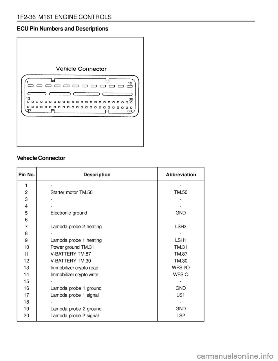
1F2-36 M161 ENGINE CONTROLS
Pin No.Abbreviation Description
1
2
3
4
5
6
7
8
9
10
11
12
13
14
15
16
17
18
19
20-
TM.50
-
-
GND
-
LSH2
-
LSH1
TM.31
TM.87
TM.30
WFS I/O
WFS O
-
GND
LS1
-
GND
LS2 -
Starter motor TM.50
-
-
Electronic ground
-
Lambda probe 2 heating
-
Lambda probe 1 heating
Power ground TM.31
V-BATTERY TM.87
V-BATTERY TM.30
Immobilizer crypto read
Immobilizer crypto write
-
Lambda probe 1 ground
Lambda probe 1 signal
-
Lambda probe 2 ground
Lambda probe 2 signal
ECU Pin Numbers and Descriptions
Vehecle Connector
Page 689 of 1463
1F2-40 M161 ENGINE CONTROLS
Application
Pin No.Abbreviation Description
-
Starter motor TM.50
-
-
Electronic ground
-
Lambda probe 2 heating
-
Lambda probe 1 heating
Power ground TM.31
V-BATTERY TM.87
V-BATTERY TM.30
Immobilizer crypto read
Immobilizer crypto write
-
Lambda probe 1 ground
Lambda probe 1 signal
-
-
-
Brake switch
-
-
-
-
-
Air conditioning clutch relay
-
-
-1
2
3
4
5
6
7
8
9
10
11
12
13
14
15
16
17
18
19
20
21
22
23
24
25
26
27
28
29
30-
TM.50
-
-
GND
-
LSH2
-
LSH1
TM.31
TM.87
TM.30
WFS I/O
WFS O
-
GND
LS1
-
-
-
BRS
-
-
-
-
-
KLIKU
-
-
--
l
-
-
l
-
-
-
l
l
l
l
l
l
-
l
l
-
-
-
¡
-
-
-
-
-
l
-
-
--
l
-
-
l
-
-
-
l
l
l
l
l
l
-
l
l
-
-
-
¡
-
-
-
-
-
l
-
-
-
l: Standard, ¡: OptionE23 ENG,
4speed A/T E23 ENG,
5speed A/T