Page 4538 of 6000
6A–42
ENGINE MECHANICAL
Crankshaft and Main Bearings
Removal
F06RW010
Legend
(1) Engine Assembly
(2) Crankshaft Pulley
(3) Timing Belt Cover
(4) Timing Belt
(5) Crankcase with Oil Pan
(6) Oil Pipe
(7) Oil Strainer(8) Oil Pump Assembly
(9) Cylinder Body Side Bolt
(10) Oil Gallery
(11) Flywheel
(12) Rear Oil Seal Retainer
(13) Connecting Rod Cap
(14) Crankshaft Main Bearing Cap
(15) Crankshaft and Main Bearing
1. Remove engine assembly.
Refer to removal procedure for Engine Assembly in
this manual.
2. Remove timing belt.
Refer to removal procedure for Timing Belt in this
manual.3. Remove oil pan and crankcase.
Refer to removal procedure for Oil Pan and
Crankcase in this manual.
4. Remove oil pipe with O-ring.
5. Remove oil strainer assembly with O-ring.
Page 4542 of 6000
6A–46
ENGINE MECHANICAL
Tighten fixing bolts to the specified torque.
Torque : 25 Nꞏm (2.5 Kgꞏm/18 lb ft)
013RW003
013RW002
13. Install timing belt.
Refer to installation procedure for Timing Belt in this
manual.
14. Install engine assembly.
Refer to installation procedure for Engine in this
manual.
Page 4586 of 6000
6A–90
ENGINE MECHANICAL
Main Data and Specification
General Specification
ItemSpecificationsItem6VD16VE1
Engine type, number of cylinders and arrangementWater cooled, four cycle V6
Form of combustion chamberPent roof type
Valve mechanism4-Cams, 4-Valves, DOHC Gear & Belt Drive
Cylinder liner typeCasted in cylinder drive
Total piston displacement3165 cc3494 cc
Cylinder bore x stroke93.4mm x 77.0mm93.4mm x 85.0mm
(3.6772 in x 3.0315 in)(3.6772 in x 3.3465 in)
Compression ratio9.1 : 1
Compression pressure at 300rpm14.0 Kg/cm
Engine idling speed rpmNon adjustable (750)
Valve clearanceIntake: 0.28 mm (0.11 in)
Exhaust: 0.30mm (0.12in)
Oil capacity5.3 liters
Ignition timingNon adjustableNon adjustable
16 BTDC at idle rpm)(20 BTDC at idle rpm)
Spark plugK16PR–P11, PK16PR11, RC10PYP4
Plug gap1.0 mm–1.1 mm(0.0394 in – 0.0433 in)
Page 4589 of 6000
6A–93
ENGINE MECHANICAL
Crankshaft main bearing, Flywheel, Crankcase, Oil pan, Timing belt tensioner, Timing pulley, Timing belt
cover, Oil pump, Oil gallery, Oil strainer and Water pump
Nꞏm (Kgꞏm/Ib ft)
E06RW039
Page 4595 of 6000
6B–2
ENGINE COOLING
General Description
030RW001
Legend
(1) Water Pump
(2) Thermostat
(3) Radiator
(4) Reserve Tank
(5) Cooling Fan
(6) Cylinder Block(7) Cylinder Head
(8) Right Bank
(9) Throttle Body
(10) Cylinder Block
(11) Cylinder Head
(12) Left Bank
(13) Heater
The cooling system is a pressurized Engine Coolant (EC)
forced circulation type which consists of a water pump,
thermostat cooling fan, radiator and other components.
The automatic transmission fluid is cooled by the EC in
radiator.
Water Pump
The EC pump is a centrifugal impeller type and is driven
by a timing belt.
030RS001
Page 4600 of 6000

ENGINE COOLING6B–7
Water Pump
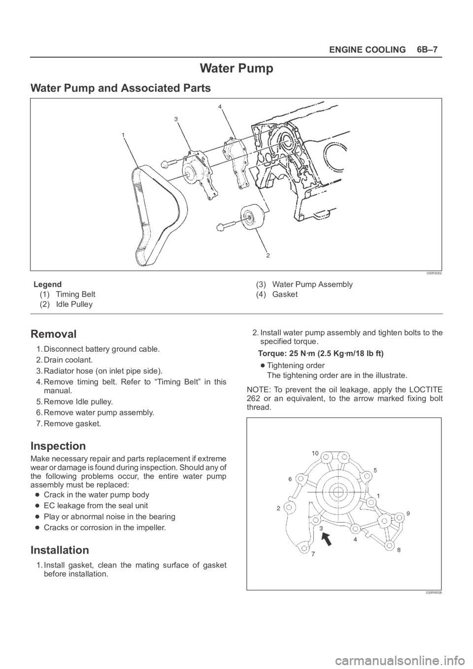
Water Pump and Associated Parts
030RS002
Legend
(1) Timing Belt
(2) Idle Pulley(3) Water Pump Assembly
(4) Gasket
Removal
1. Disconnect battery ground cable.
2. Drain coolant.
3. Radiator hose (on inlet pipe side).
4. Remove timing belt. Refer to “Timing Belt” in this
manual.
5. Remove Idle pulley.
6. Remove water pump assembly.
7. Remove gasket.
Inspection
Make necessary repair and parts replacement if extreme
wear or damage is found during inspection. Should any of
the following problems occur, the entire water pump
assembly must be replaced:
Crack in the water pump body
EC leakage from the seal unit
Play or abnormal noise in the bearing
Cracks or corrosion in the impeller.
Installation
1. Install gasket, clean the mating surface of gasket
before installation.2. Install water pump assembly and tighten bolts to the
specified torque.
Torque: 25 Nꞏm (2.5 Kgꞏm/18 lb ft)
Tightening order
The tightening order are in the illustrate.
NOTE: To prevent the oil leakage, apply the LOCTITE
262 or an equivalent, to the arrow marked fixing bolt
thread.
030RW008
Page 4601 of 6000

6B–8
ENGINE COOLING
3. Idle pulley
Install idle pulley and tighten bolt to the specified
torque.
Torque: 52 Nꞏm (5.3 Kgꞏm/38 lb ft)4. Timing beltInstall timing belt. Refer to timing belt installation
step in “Timing Belt” in this manual.
5. Connect radiator inlet hose and replenish EC.
6. Connect battery ground cable.
Thermostat
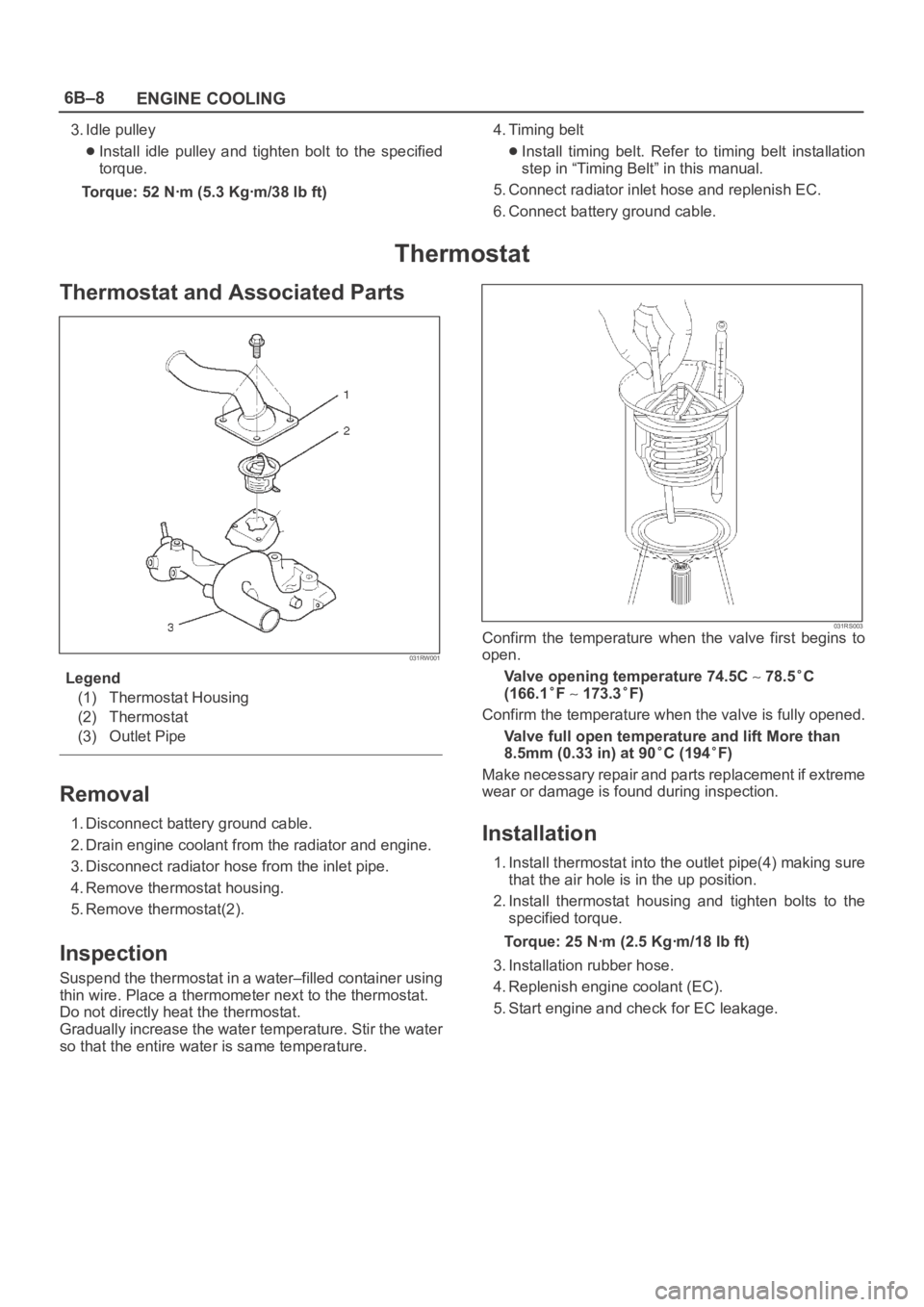
Thermostat and Associated Parts
031RW001
Legend
(1) Thermostat Housing
(2) Thermostat
(3) Outlet Pipe
Removal
1. Disconnect battery ground cable.
2. Drain engine coolant from the radiator and engine.
3. Disconnect radiator hose from the inlet pipe.
4. Remove thermostat housing.
5. Remove thermostat(2).
Inspection
Suspend the thermostat in a water–filled container using
thin wire. Place a thermometer next to the thermostat.
Do not directly heat the thermostat.
Gradually increase the water temperature. Stir the water
so that the entire water is same temperature.
031RS003Confirm the temperature when the valve first begins to
open.
Valve opening temperature 74.5C
78.5C
(166.1
F 173.3F)
Confirm the temperature when the valve is fully opened.
Valve full open temperature and lift More than
8.5mm (0.33 in) at 90
C (194F)
Make necessary repair and parts replacement if extreme
wear or damage is found during inspection.
Installation
1. Install thermostat into the outlet pipe(4) making sure
that the air hole is in the up position.
2. Install thermostat housing and tighten bolts to the
specified torque.
Torque: 25 Nꞏm (2.5 Kgꞏm/18 lb ft)
3. Installation rubber hose.
4. Replenish engine coolant (EC).
5. Start engine and check for EC leakage.
Page 4739 of 6000

6E–82
ENGINE DRIVEABILITY AND EMISSIONS
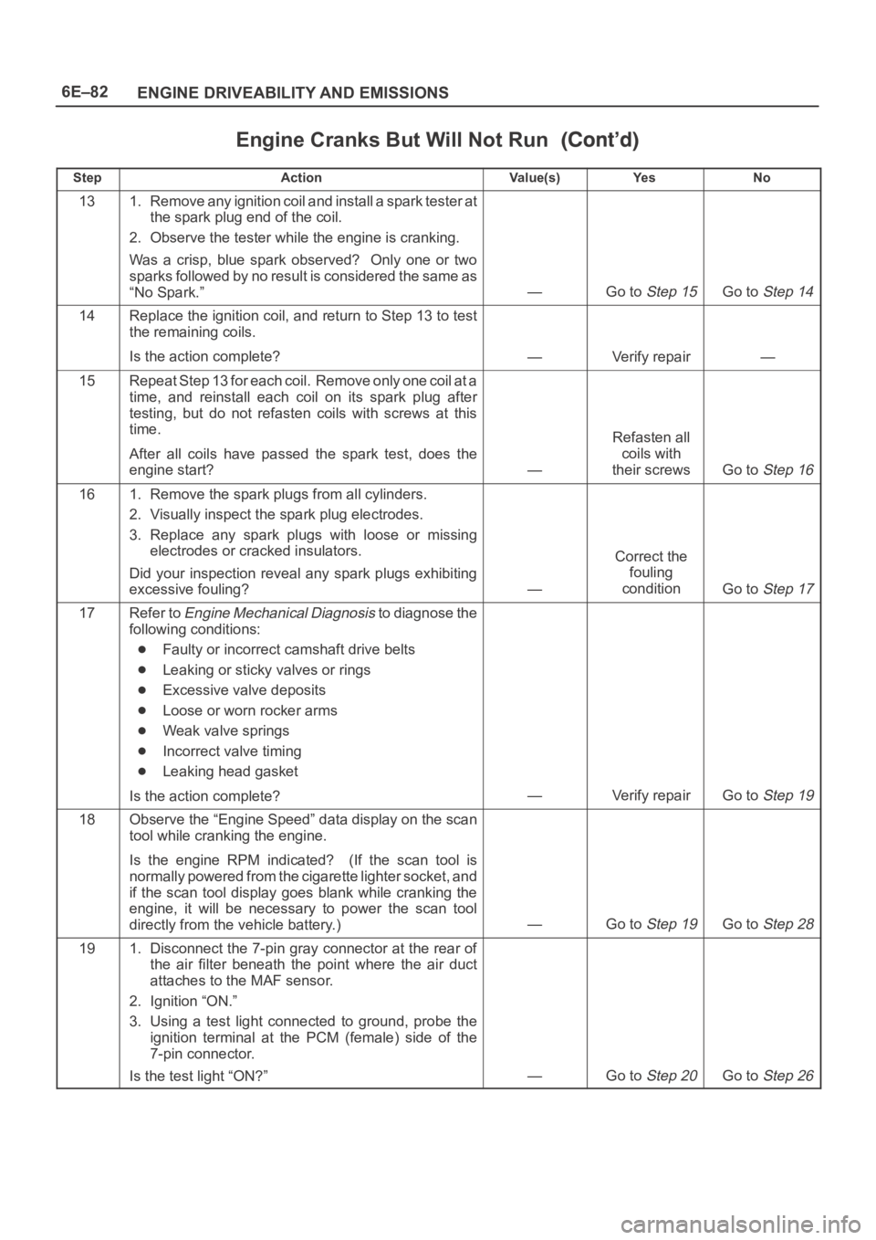
Engine Cranks But Will Not Run
StepNo Ye s Va l u e ( s ) Action
131. Remove any ignition coil and install a spark tester at
the spark plug end of the coil.
2. Observe the tester while the engine is cranking.
Was a crisp, blue spark observed? Only one or two
sparks followed by no result is considered the same as
“No Spark.”
—Go to Step 15Go to Step 14
14Replace the ignition coil, and return to Step 13 to test
the remaining coils.
Is the action complete?
—Verify repair—
15Repeat Step 13 for each coil. Remove only one coil at a
time, and reinstall each coil on its spark plug after
testing, but do not refasten coils with screws at this
time.
After all coils have passed the spark test, does the
engine start?
—
Refasten all
coils with
their screws
Go to Step 16
161. Remove the spark plugs from all cylinders.
2. Visually inspect the spark plug electrodes.
3. Replace any spark plugs with loose or missing
electrodes or cracked insulators.
Did your inspection reveal any spark plugs exhibiting
excessive fouling?
—
Correct the
fouling
condition
Go to Step 17
17Refer to Engine Mechanical Diagnosis to diagnose the
following conditions:
Faulty or incorrect camshaft drive belts
Leaking or sticky valves or rings
Excessive valve deposits
Loose or worn rocker arms
Weak valve springs
Incorrect valve timing
Leaking head gasket
Is the action complete?
—Verify repairGo to Step 19
18Observe the “Engine Speed” data display on the scan
tool while cranking the engine.
Is the engine RPM indicated? (If the scan tool is
normally powered from the cigarette lighter socket, and
if the scan tool display goes blank while cranking the
engine, it will be necessary to power the scan tool
directly from the vehicle battery.)
—Go to Step 19Go to Step 28
191. Disconnect the 7-pin gray connector at the rear of
the air filter beneath the point where the air duct
attaches to the MAF sensor.
2. Ignition “ON.”
3. Using a test light connected to ground, probe the
ignition terminal at the PCM (female) side of the
7-pin connector.
Is the test light “ON?”
—Go to Step 20Go to Step 26