1998 OPEL FRONTERA timing belt
[x] Cancel search: timing beltPage 1791 of 6000
6A – 58 ENGINE MECHANICAL
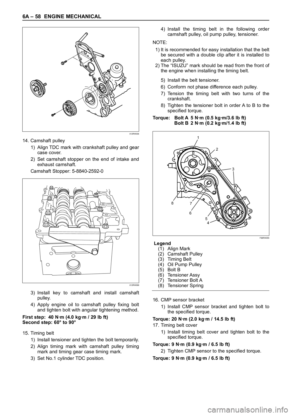
14. Camshaft pulley
1) Align TDC mark with crankshaft pulley and gear
case cover.
2) Set camshaft stopper on the end of intake and
exhaust camshaft.
Camshaft Stopper: 5-8840-2592-0
3) Install key to camshaft and install camshaft
pulley.
4) Apply engine oil to camshaft pulley fixing bolt
and tighten bolt with angular tightening method.
First step: 40 Nꞏm (4.0 kgꞏm / 29 lb ft)
Second step: 60° to 90°
15. Timing belt
1) Install tensioner and tighten the bolt temporarily.
2) Align timing mark with camshaft pulley timing
mark and timing gear case timing mark.
3) Set No.1 cylinder TDC position.4) Install the timing belt in the following order
camshaft pulley, oil pump pulley, tensioner.
NOTE:
1) It is recommended for easy installation that the belt
be secured with a double clip after it is installed to
each pulley.
2) The “ISUZU” mark should be read from the front of
the engine when installing the timing belt.
5) Install the belt tensioner.
6) Conform not phase difference each pulley.
7) Tension the timing belt with two turns of the
crankshaft.
8) Tighten the tensioner bolt in order A to B to the
specified torque.
Torque: Bolt A 5 Nꞏm (0.5 kgꞏm/3.6 lb ft)
Bolt B 2 Nꞏm (0.2 kgꞏm/1.4 lb ft)
Legend
(1) Align Mark
(2) Camshaft Pulley
(3) Timing Belt
(4) Oil Pump Pulley
(5) Bolt B
(6) Tensioner Assy
(7) Tensioner Bolt A
(8) Tensioner Spring
16. CMP sensor bracket
1) Install CMP sensor bracket and tighten bolt to
the specified torque.
Torque: 20 Nꞏm (2.0 kgꞏm / 14.5 lb ft)
17. Timing belt cover
1) Install timing belt cover and tighten bolt to the
specified torque.
Torque: 9 Nꞏm (0.9 kgꞏm / 6.5 lb ft)
2) Tighten CMP sensor to the specified torque.
Torque: 9 Nꞏm (0.9 kgꞏm / 6.5 lb ft)
012RW036
012RW099
1
2
3
8
67
4 5
F06RW055
Page 1793 of 6000
6A – 60 ENGINE MECHANICAL
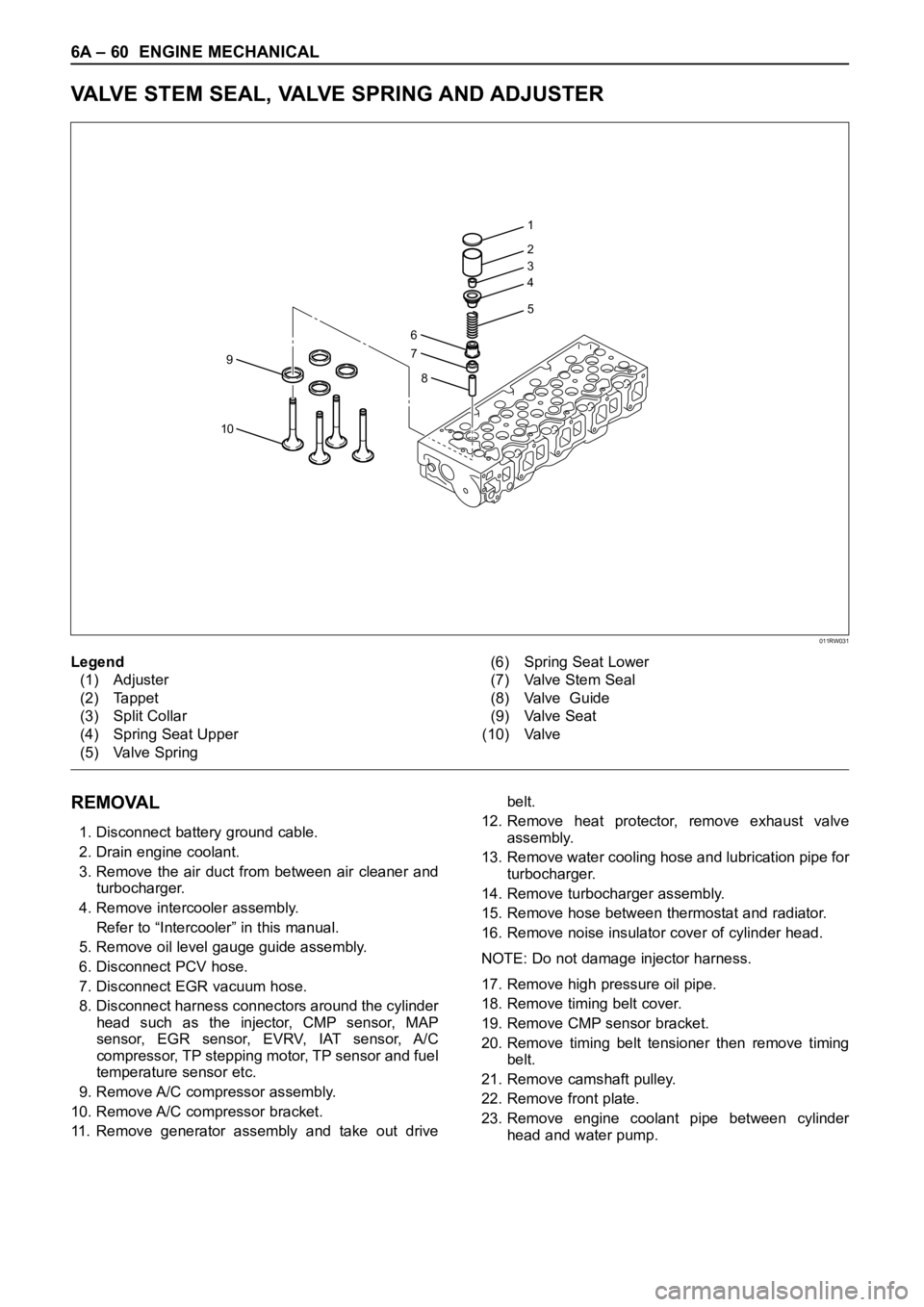
VALVE STEM SEAL, VALVE SPRING AND ADJUSTER
REMOVAL
1. Disconnect battery ground cable.
2. Drain engine coolant.
3. Remove the air duct from between air cleaner and
turbocharger.
4. Remove intercooler assembly.
Refer to “Intercooler” in this manual.
5. Remove oil level gauge guide assembly.
6. Disconnect PCV hose.
7. Disconnect EGR vacuum hose.
8. Disconnect harness connectors around the cylinder
head such as the injector, CMP sensor, MAP
sensor, EGR sensor, EVRV, IAT sensor, A/C
compressor, TP stepping motor, TP sensor and fuel
temperature sensor etc.
9. Remove A/C compressor assembly.
10. Remove A/C compressor bracket.
11. Remove generator assembly and take out drivebelt.
12. Remove heat protector, remove exhaust valve
assembly.
13. Remove water cooling hose and lubrication pipe for
turbocharger.
14. Remove turbocharger assembly.
15. Remove hose between thermostat and radiator.
16. Remove noise insulator cover of cylinder head.
NOTE: Do not damage injector harness.
17. Remove high pressure oil pipe.
18. Remove timing belt cover.
19. Remove CMP sensor bracket.
20. Remove timing belt tensioner then remove timing
belt.
21. Remove camshaft pulley.
22. Remove front plate.
23. Remove engine coolant pipe between cylinder
head and water pump.
1
2
3
4
5
6
9
10
7
8
011RW031
Legend
(1) Adjuster
(2) Tappet
(3) Split Collar
(4) Spring Seat Upper
(5) Valve Spring(6) Spring Seat Lower
(7) Valve Stem Seal
(8) Valve Guide
(9) Valve Seat
(10) Valve
Page 1799 of 6000
6A – 66 ENGINE MECHANICAL
INSTALLATION
1. Valve stem seal
1) Use the special tool to install the stem seal to the
valve guide.
Stem Seal Installer: 5-8840-2033-0
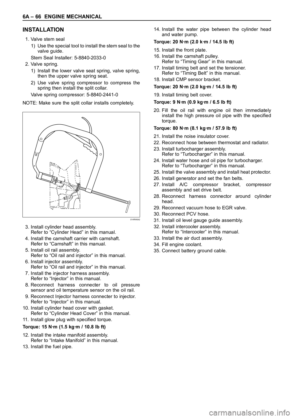
2. Valve spring.
1) Install the lower valve seat spring, valve spring,
then the upper valve spring seat.
2) Use valve spring compressor to compress the
spring then install the split collar.
Valve spring compressor: 5-8840-2441-0
NOTE: Make sure the split collar installs completely.
3. Install cylinder head assembly.
Refer to “Cylinder Head” in this manual.
4. Install the camshaft carrier with camshaft.
Refer to “Camshaft” in this manual.
5. Install oil rail assembly.
Refer to “Oil rail and injector” in this manual.
6. Install injector assembly.
Refer to “Oil rail and injector” in this manual.
7. Install the injector harness assembly.
Refer to “Injector” in this manual.
8. Reconnect harness connecter to oil pressure
sensor and oil temperature sensor on the oil rail.
9. Reconnect Injector harness connecter to injector.
Refer to “Injector” in this manual.
10. Install cylinder head cover with gasket.
Refer to “Cylinder Head Cover” in this manual.
11. Install glow plug with specified torque.
Torque: 15 Nꞏm (1.5 kgꞏm / 10.8 lb ft)
12. Install the intake manifold assembly.
Refer to “Intake Manifold” in this manual.
13. Install the fuel pipe.14. Install the water pipe between the cylinder head
and water pump.
Torque: 20 Nꞏm (2.0 kꞏm / 14.5 lb ft)
15. Install the front plate.
16. Install the camshaft pulley.
Refer to “Timing Gear” in this manual.
17. Install timing belt and set the tensioner.
Refer to “Timing Belt” in this manual.
18. Install CMP sensor bracket.
Torque: 20 Nꞏm (2.0 kgꞏm / 14.5 lb ft)
19. Install timing belt cover.
Torque: 9 Nꞏm (0.9 kgꞏm / 6.5 lb ft)
20. Fill the oil rail with engine oil then immediately
install the high pressure oil pipe with the specified
torque.
Torque: 80 Nꞏm (8.1 kgꞏm / 57.9 lb ft)
21. Install the noise insulator cover.
22. Reconnect hose between thermostat and radiator.
23. Install turbocharger assembly.
Refer to “Turbocharger” in this manual.
24. Install water hose and oil pipe for turbocharger.
Refer to “Turbocharger” in this manual.
25. Install the valve assembly and install heat protector.
26. Install generator and set the fan belts.
27. Install A/C compressor bracket, compressor
assembly and set drive belt.
28. Reconnect harness connector around cylinder
head.
29. Reconnect vacuum hose to EGR valve.
30. Reconnect PCV hose.
31. Install oil level gauge guide assembly.
32. Install intercooler assembly.
Refer to “Intercooler” in this manual.
33. Install the air duct assembly.
34. Fill engine coolant.
35. Connect battery ground cable.
014RW042
Page 1805 of 6000
6A – 72 ENGINE MECHANICAL
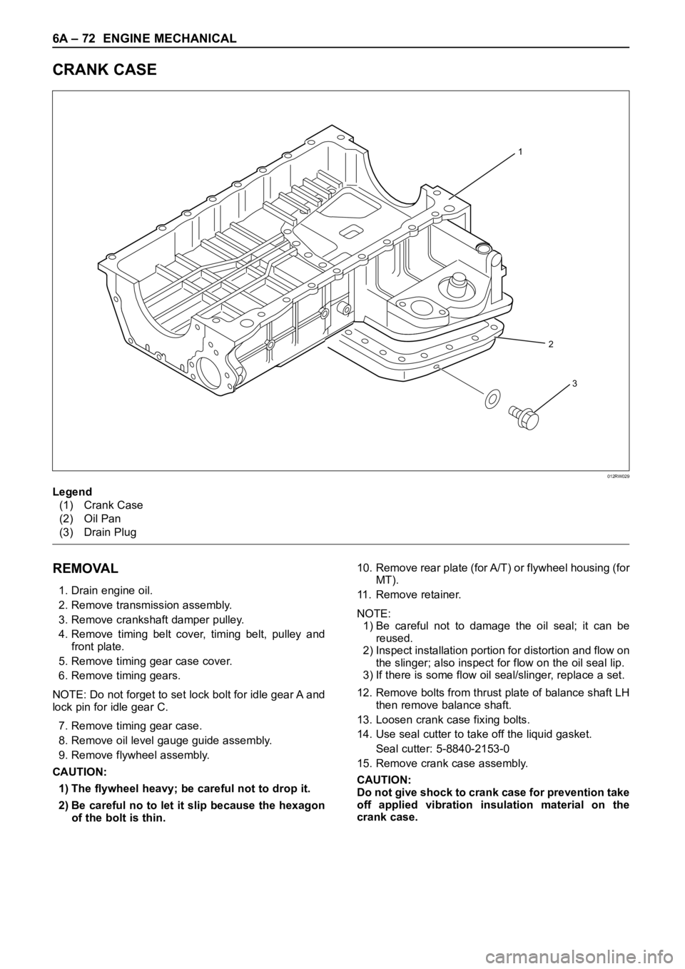
CRANK CASE
REMOVAL
1. Drain engine oil.
2. Remove transmission assembly.
3. Remove crankshaft damper pulley.
4. Remove timing belt cover, timing belt, pulley and
front plate.
5. Remove timing gear case cover.
6. Remove timing gears.
NOTE: Do not forget to set lock bolt for idle gear A and
lock pin for idle gear C.
7. Remove timing gear case.
8. Remove oil level gauge guide assembly.
9. Remove flywheel assembly.
CAUTION:
1) The flywheel heavy; be careful not to drop it.
2) Be careful no to let it slip because the hexagon
of the bolt is thin.10. Remove rear plate (for A/T) or flywheel housing (for
MT).
11. Remove retainer.
NOTE:
1) Be careful not to damage the oil seal; it can be
reused.
2) Inspect installation portion for distortion and flow on
the slinger; also inspect for flow on the oil seal lip.
3) If there is some flow oil seal/slinger, replace a set.
12. Remove bolts from thrust plate of balance shaft LH
then remove balance shaft.
13. Loosen crank case fixing bolts.
14. Use seal cutter to take off the liquid gasket.
Seal cutter: 5-8840-2153-0
15. Remove crank case assembly.
CAUTION:
Do not give shock to crank case for prevention take
off applied vibration insulation material on the
crank case.
1
2
3
012RW029
Legend
(1) Crank Case
(2) Oil Pan
(3) Drain Plug
Page 1806 of 6000
ENGINE MECHANICAL 6A – 73
INSTALLATION
1. Install relief valve (if it was removed).
Torque: 30 Nꞏm (3.1 kgꞏm / 22 lb ft)
2. Insert O-ring to strainer, install strainer and tighten
to specified torque.
Torque: 20 Nꞏm (2.0 kgꞏm / 14.5 lb ft)
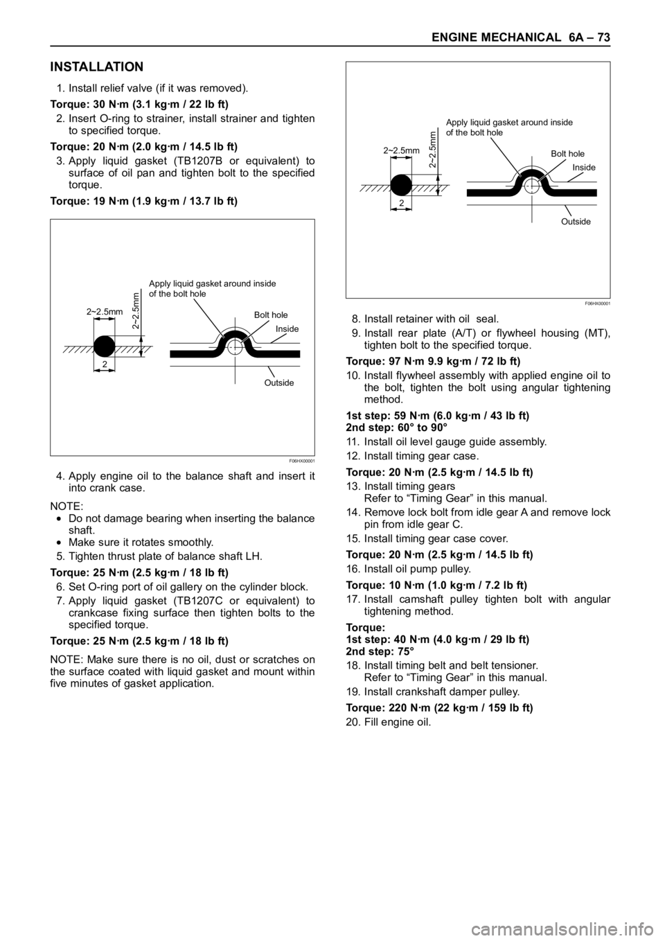
3. Apply liquid gasket (TB1207B or equivalent) to
surface of oil pan and tighten bolt to the specified
torque.
Torque: 19 Nꞏm (1.9 kgꞏm / 13.7 lb ft)
4. Apply engine oil to the balance shaft and insert it
into crank case.
NOTE:
Do not damage bearing when inserting the balance
shaft.
Make sure it rotates smoothly.
5. Tighten thrust plate of balance shaft LH.
Torque: 25 Nꞏm (2.5 kgꞏm / 18 lb ft)
6. Set O-ring port of oil gallery on the cylinder block.
7. Apply liquid gasket (TB1207C or equivalent) to
crankcase fixing surface then tighten bolts to the
specified torque.
Torque: 25 Nꞏm (2.5 kgꞏm / 18 lb ft)
NOTE: Make sure there is no oil, dust or scratches on
the surface coated with liquid gasket and mount within
five minutes of gasket application.8. Install retainer with oil seal.
9. Install rear plate (A/T) or flywheel housing (MT),
tighten bolt to the specified torque.
Torque: 97 Nꞏm 9.9 kgꞏm / 72 lb ft)
10. Install flywheel assembly with applied engine oil to
the bolt, tighten the bolt using angular tightening
method.
1st step: 59 Nꞏm (6.0 kgꞏm / 43 lb ft)
2nd step: 60° to 90°
11. Install oil level gauge guide assembly.
12. Install timing gear case.
Torque: 20 Nꞏm (2.5 kgꞏm / 14.5 lb ft)
13. Install timing gears
Refer to “Timing Gear” in this manual.
14. Remove lock bolt from idle gear A and remove lock
pin from idle gear C.
15. Install timing gear case cover.
Torque: 20 Nꞏm (2.5 kgꞏm / 14.5 lb ft)
16. Install oil pump pulley.
Torque: 10 Nꞏm (1.0 kgꞏm / 7.2 lb ft)
17. Install camshaft pulley tighten bolt with angular
tightening method.
To r q u e :
1st step: 40 Nꞏm (4.0 kgꞏm / 29 lb ft)
2nd step: 75°
18. Install timing belt and belt tensioner.
Refer to “Timing Gear” in this manual.
19. Install crankshaft damper pulley.
Torque: 220 Nꞏm (22 kgꞏm / 159 lb ft)
20. Fill engine oil.
2
2~2.5mm
2~2.5mm
Apply liquid gasket around inside
of the bolt hole
Bolt hole
Inside
Outside
F06HX00001
2
2~2.5mm
2~2.5mm
Apply liquid gasket around inside
of the bolt hole
Bolt hole
Inside
Outside
F06HX00001
Page 1860 of 6000
ENGINE FUEL 6C – 15
HIGH PRESSURE OIL PUMP
REMOVAL
1. Disconnect battery ground cable.
2. Remove air cleaner cover and air duct
3. Intercooler assembly
Refer to “Intercooler” in this manual.
4. Remove high pressure oil pipe
5. Timing belt cover
Disconnect CMP sensor cable.
Remove CMP sensor bracket.
6. Tensioner
7. Timing Belt
8. Remove high pressure oil pump timing pulley
9. Remove crankshaft damper pulley
10. Remove timing gear case cover
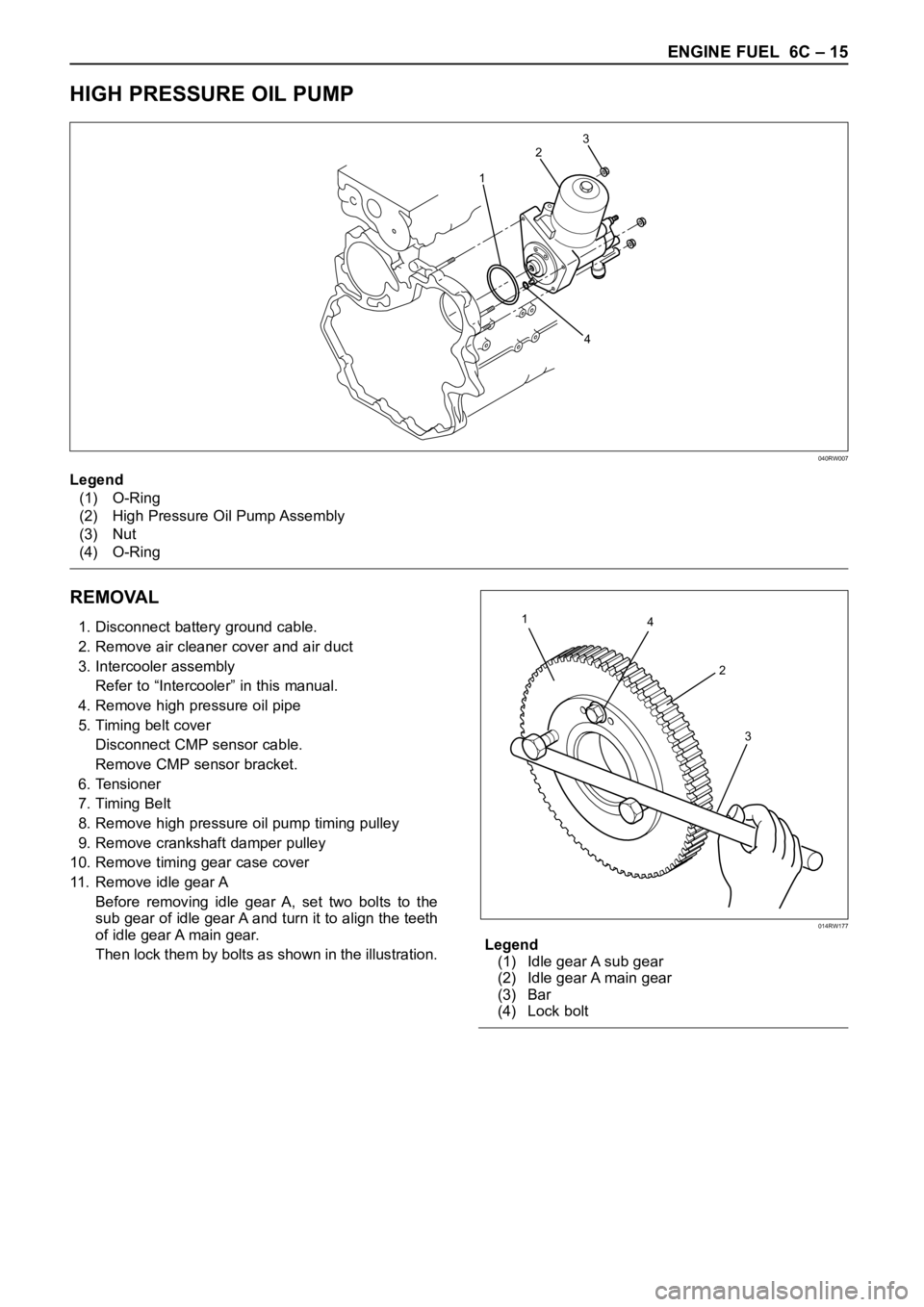
11. Remove idle gear A
Before removing idle gear A, set two bolts to the
sub gear of idle gear A and turn it to align the teeth
of idle gear A main gear.
Then lock them by bolts as shown in the illustration.Legend
(1) Idle gear A sub gear
(2) Idle gear A main gear
(3) Bar
(4) Lock bolt
1
2
43
Legend
(1) O-Ring
(2) High Pressure Oil Pump Assembly
(3) Nut
(4) O-Ring
040RW007
4 1
2
3
014RW177
Page 1863 of 6000
6C – 18 ENGINE FUEL
4. Remove lock bolt of idle gear A.
5. Install timing gear case cover.
Refer to “Timing gear” in this manual.
6. Install front plate.
Torque: 20 Nꞏm (2.0 kgꞏm/14.5 lb ft)
7. Install timing pulley of high pressure oil pump.
Torque: 10 Nꞏm (1.0 kgꞏm/7.2 lb ft)
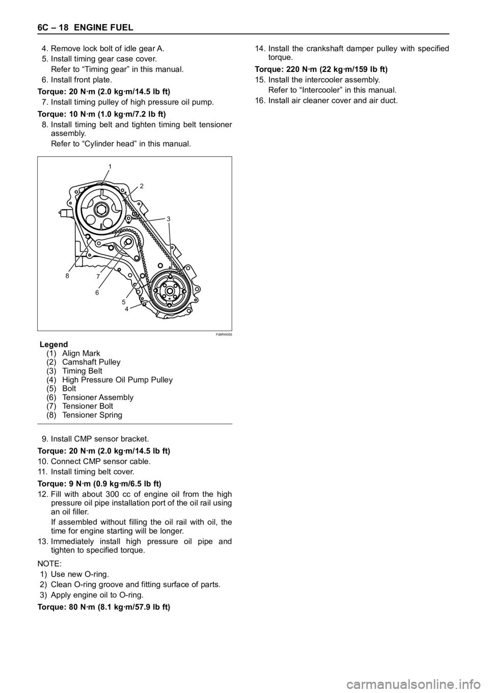
8. Install timing belt and tighten timing belt tensioner
assembly.
Refer to “Cylinder head” in this manual.
Legend
(1) Align Mark
(2) Camshaft Pulley
(3) Timing Belt
(4) High Pressure Oil Pump Pulley
(5) Bolt
(6) Tensioner Assembly
(7) Tensioner Bolt
(8) Tensioner Spring
9. Install CMP sensor bracket.
Torque: 20 Nꞏm (2.0 kgꞏm/14.5 lb ft)
10. Connect CMP sensor cable.
11. Install timing belt cover.
Torque: 9 Nꞏm (0.9 kgꞏm/6.5 lb ft)
12. Fill with about 300 cc of engine oil from the high
pressure oil pipe installation port of the oil rail using
an oil filler.
If assembled without filling the oil rail with oil, the
time for engine starting will be longer.
13. Immediately install high pressure oil pipe and
tighten to specified torque.
NOTE:
1) Use new O-ring.
2) Clean O-ring groove and fitting surface of parts.
3) Apply engine oil to O-ring.
Torque: 80 Nꞏm (8.1 kgꞏm/57.9 lb ft)14. Install the crankshaft damper pulley with specified
torque.
Torque: 220 Nꞏm (22 kgꞏm/159 lb ft)
15. Install the intercooler assembly.
Refer to “Intercooler” in this manual.
16. Install air cleaner cover and air duct.
1
2
3
8
67
4 5
F06RW055
Page 1943 of 6000
6E–50
4JX1–TC ENGINE DRIVEABILITY AND EMISSIONS
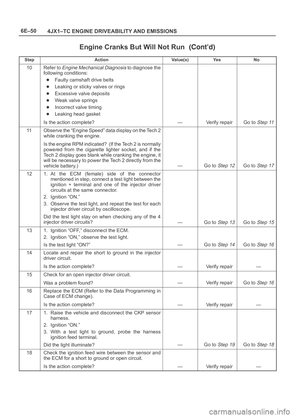
Engine Cranks But Will Not Run
StepNo Ye s Va l u e ( s ) Action
10Refer to Engine Mechanical Diagnosis to diagnose the
following conditions:
Faulty camshaft drive belts
Leaking or sticky valves or rings
Excessive valve deposits
Weak valve springs
Incorrect valve timing
Leaking head gasket
Is the action complete?
—Verify repairGo to Step 11
11Observe the “Engine Speed” data display on the Tech 2
while cranking the engine.
Is the engine RPM indicated? (If the Tech 2 is normally
powered from the cigarette lighter socket, and if the
Tech 2 display goes blank while cranking the engine, it
will be necessary to power the Tech 2 directly from the
vehicle battery.)
—Go to Step 12Go to Step 17
121. At the ECM (female) side of the connector
mentioned in step, connect a test light between the
ignition + terminal and one of the injector driver
circuits at the same connector.
2. Ignition “ON.”
3. Observe the test light, and repeat the test for each
injector driver circuit by oscilloscope.
Did the test light stay on when checking any of the 4
injector driver circuits?
—Go to Step 13Go to Step 15
131. Ignition “OFF,” disconnect the ECM.
2. Ignition “ON,” observe the test light.
Is the test light “ON?”
—Go to Step 14Go to Step 16
14Locate and repair the short to ground in the injector
driver circuit.
Is the action complete?
—Verify repair—
15Check for an open injector driver circuit.
Was a problem found?
—Verify repairGo to Step 16
16Replace the ECM (Refer to the Data Programming in
Case of ECM change).
Is the action complete?
—Verify repair—
171. Raise the vehicle and disconnect the CKP sensor
harness.
2. Ignition “ON.”
3. With a test light to ground, probe the harness
ignition feed terminal.
Did the light illuminate?
—Go to Step 19Go to Step 18
18Check the ignition feed wire between the sensor and
the ECM for a short to ground or open circuit.
Is the action complete?
—Verify repair—