Page 3556 of 6000

10A–5
CRUISE CONTROL SYSTEM
Cruise Control Main Switch
Removal
1. Disconnect the battery ground cable.
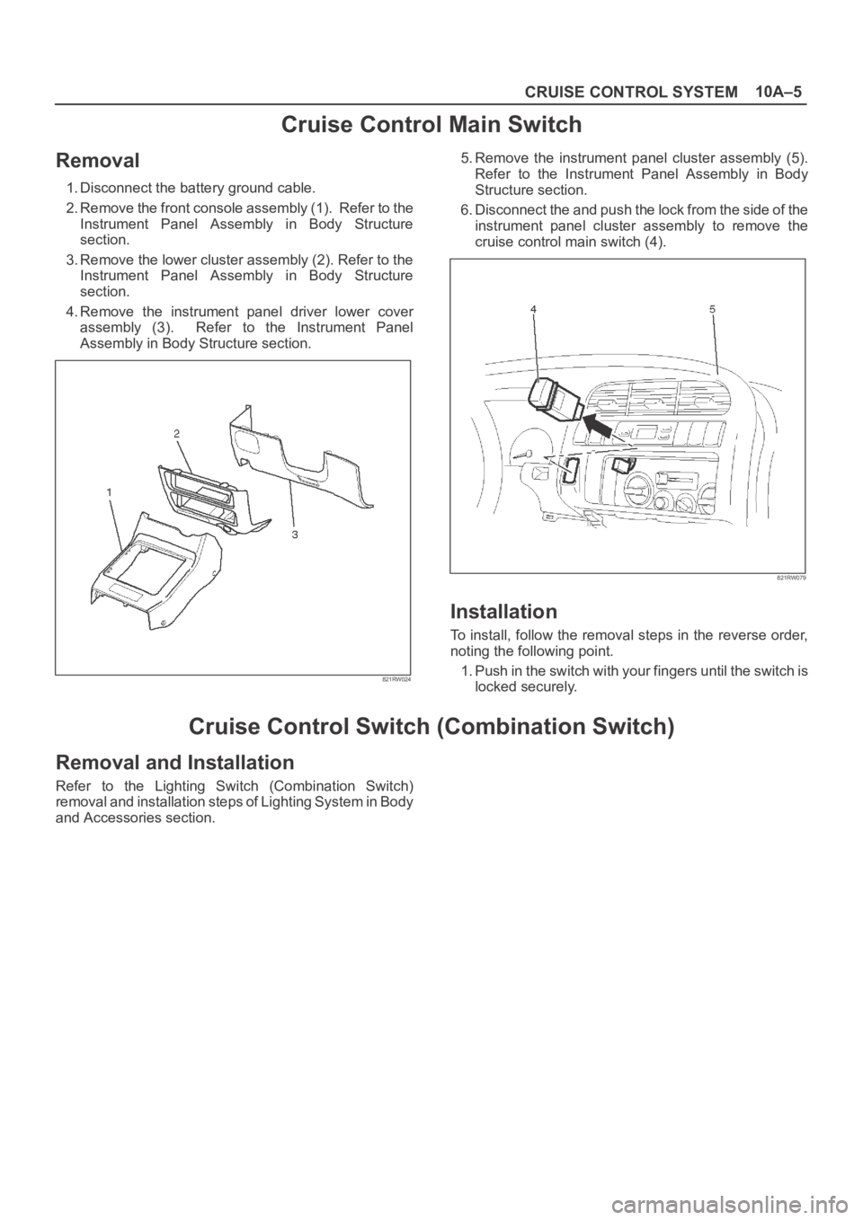
2. Remove the front console assembly (1). Refer to the
Instrument Panel Assembly in Body Structure
section.
3. Remove the lower cluster assembly (2). Refer to the
Instrument Panel Assembly in Body Structure
section.
4. Remove the instrument panel driver lower cover
assembly (3). Refer to the Instrument Panel
Assembly in Body Structure section.
821RW024
5. Remove the instrument panel cluster assembly (5).
Refer to the Instrument Panel Assembly in Body
Structure section.
6. Disconnect the and push the lock from the side of the
instrument panel cluster assembly to remove the
cruise control main switch (4).
821RW079
Installation
To install, follow the removal steps in the reverse order,
noting the following point.
1. Push in the switch with your fingers until the switch is
locked securely.
Cruise Control Switch (Combination Switch)
Removal and Installation
Refer to the Lighting Switch (Combination Switch)
removal and installation steps of Lighting System in Body
and Accessories section.
Page 3565 of 6000
PAGE BACK PAGE NEXT
THIS MALUAL INCLUDES THE FOLLOWING SECTIONS:
SECTION No. CONTRNTS
5A BRAKE CONTROL SYSTEM
5B ANTI-LOCK BRAKE SYSTEM
5C POWER ASSISTED BRAKE SYSTEM
5D PARKING BRAKES
HOME
5A
5B
5C
5D
Page 3569 of 6000
PAGE BACK PAGE NEXT
THIS MALUAL INCLUDES THE FOLLOWING SECTIONS:
SECTION No. CONTRNTS
8A LIGHTING SYSTEM
8B WIPER / WASHER SYSTEM
8C ENTERTAINMENT
8D WIRING SYSTEM
8E METER AND GAUGE
8F BODY STRUCTURE
8G SEATS
8H SECURITY AND LOCKS
8I SUN ROOF/CONVERTIBLE TOP
8J EXTERIOR / INTERIOR TRIM
HOME
8A
8B
8C
8D
8E
8F
8G
8H
8I
8J
Page 3573 of 6000

Service Precaution
WARNING: THIS VEHICLE HAS A SUPPLEMENTAL
RESTRAINT SYSTEM (SRS). REFER TO THE SRS
COMPONENT AND WIRING LOCATION VIEW IN
ORDER TO DETERMINE WHETHER YOU ARE
PERFORMING SERVICE ON OR NEAR THE SRS
COMPONENTS OR THE SRS WIRING. WHEN YOU
ARE PERFORMING SERVICE ON OR NEAR THE
SRS COMPONENTS OR THE SRS WIRING, REFER
TO THE SRS SERVICE INFORMATION. FAILURE
TO FOLLOW WARNINGS COULD RESULT IN
POSSIBLE AIR BAG DEPLOYMENT, PERSONAL
INJURY, OR OTHERWISE UNNEEDED SRS
SYSTEM REPAIRS.CAUTION: Always use the correct fastener in the
proper location. When you replace a fastener, use
ONLY the exact part number for that application.
ISUZU will call out those fasteners that require a
replacement after removal. ISUZU will also call out
the fasteners that require thread lockers or thread
sealant. UNLESS OTHERWISE SPECIFIED, do not
use supplemental coatings (Paints, greases, or
other corrosion inhibitors) on threaded fasteners
or fasteners joint interfaces. Generally, such
coatings adversely affect the fastener torque and
the joint clamping force, and may damage the
fastener. When you install fasteners, use the
correct tightening sequence and specification.
Following these instructions can help you avoid
damage to parts and systems.
Page 3586 of 6000

Service Precaution
WARNING: THIS VEHICLE HAS A SUPPLEMENTAL
RESTRAINT SYSTEM (SRS). REFER TO THE SRS
COMPONENT AND WIRING LOCATION VIEW IN
ORDER TO DETERMINE WHETHER YOU ARE
PERFORMING SERVICE ON OR NEAR THE SRS
COMPONENTS OR THE SRS WIRING. WHEN YOU
ARE PERFORMING SERVICE ON OR NEAR THE
SRS COMPONENTS OR THE SRS WIRING, REFER
TO THE SRS SERVICE INFORMATION. FAILURE
TO FOLLOW WARNINGS COULD RESULT IN
POSSIBLE AIR BAG DEPLOYMENT, PERSONAL
INJURY, OR OTHERWISE UNNEEDED SRS
SYSTEM REPAIRS.CAUTION: Always use the correct fastener in the
proper location. When you replace a fastener, use
ONLY the exact part number for that application.
ISUZU will call out those fasteners that require a
replacement after removal. ISUZU will also call out
the fasteners that require thread lockers or thread
sealant. UNLESS OTHERWISE SPECIFIED, do not
use supplemental coatings (Paints, greases, or
other corrosion inhibitors) on threaded fasteners
or fasteners joint interfaces. Generally, such
coatings adversely affect the fastener torque and
the joint clamping force, and may damage the
fastener. When you install fasteners, use the
correct tightening sequence and specification.
Following these instructions can help you avoid
damage to parts and systems.
Page 3691 of 6000
B-5
BLOWER
MOTOR2
B-5
1
I-51
3I-51
I-51I-51
MAX HI
RELAY POWER
TRANSISTORI-50
I-50
4
H-202
H-26
10
1
3
H-20
121 2L/B
0.5P/G
12
I-32
16 I-32
P-2
0.85W/G5W
5W 0.5R/W
0.3B0.5R/W 0.3R/W
TAIL RELAY(4) ILLUMINATION
CONTROLLER0.5G/R 0.85G/R
1.25B
1.25B1.25B
0.5B
9 I-32 5W 3W
BATT
FL-1
80A
MAIN4B-36
33L/R
C-19 25A
BLOWERC-20 10A
AIR CON
3L 2L/B
0.3BR
0.5BR0.3BR 2/B 0.3GR
0.3GR/L0.5L/B
2/B
B-36
20
H-27 2
B-36H-14
1
B-36HEATER & A/C RELAY
STARTER RELAY(1)
H-141
H-1310
I-328
H-269
10 C-16
10A CLOCK ROOM
BODY-RHBODY-LH
B-18
B-19
B-1
AUTO A/C CONTROL UNITAUTO A/C CONTROL UNIT
I-3217
14 35 2112 337
I-32
22
29 6I-331 H-20
14
H-16
M
192B
I-33
2I-50
D08RY00118
Page 3695 of 6000
0.5R/G
ILLUMINATION
CONTROLLER
12
I-32
157
I-32
16 I-3229
P-2
0.85W/R5W
3L 2L/B 2L/BBATT.
5W 0.5R/W
0.3B0.5R/W 0.3R/W
TAIL REAY(4) 0.5G/R 0.85R/W
1.25B
1.25B
0.5B
9 I-3236 5W 3W FL-1
80A
MAIN4
B-36
33L/RC-20 10A
AIR CON
C-19 25A
BLOWER
BLOWER
MOTOR
B-36 2
B-36H-14
1
B-36HEATER A/C RELAY
STARTER SW (ACC)
H-141
I-328
H-265
10 C-16 10A
CLOCK ROOM
C-11 10A
AUDIO
F-12 10A
TAIL-RH
BODY-LHB-19
BODY-RHB-22BH-481.25B 15
H-2614
I-50 2
AUTO A/C CONTORL UNIT AUTO A/C CONTORL UNIT
I-32
6
H-16
0.5BR 2B 2B0.3GR/W0.5L/B
0.3BR 0.3BR
19
I-33
33
22 21 3512
H-48
0.3GR/L
MAX HI
RELAY POWER
TRANSISTOR
I-51
3
H-4811
I-51
4I-50
3
I-512I-501
H-4815
I-511
B-51
B-5
2
H-484
M
17
I-33
14
D08RY00121
Page 3699 of 6000

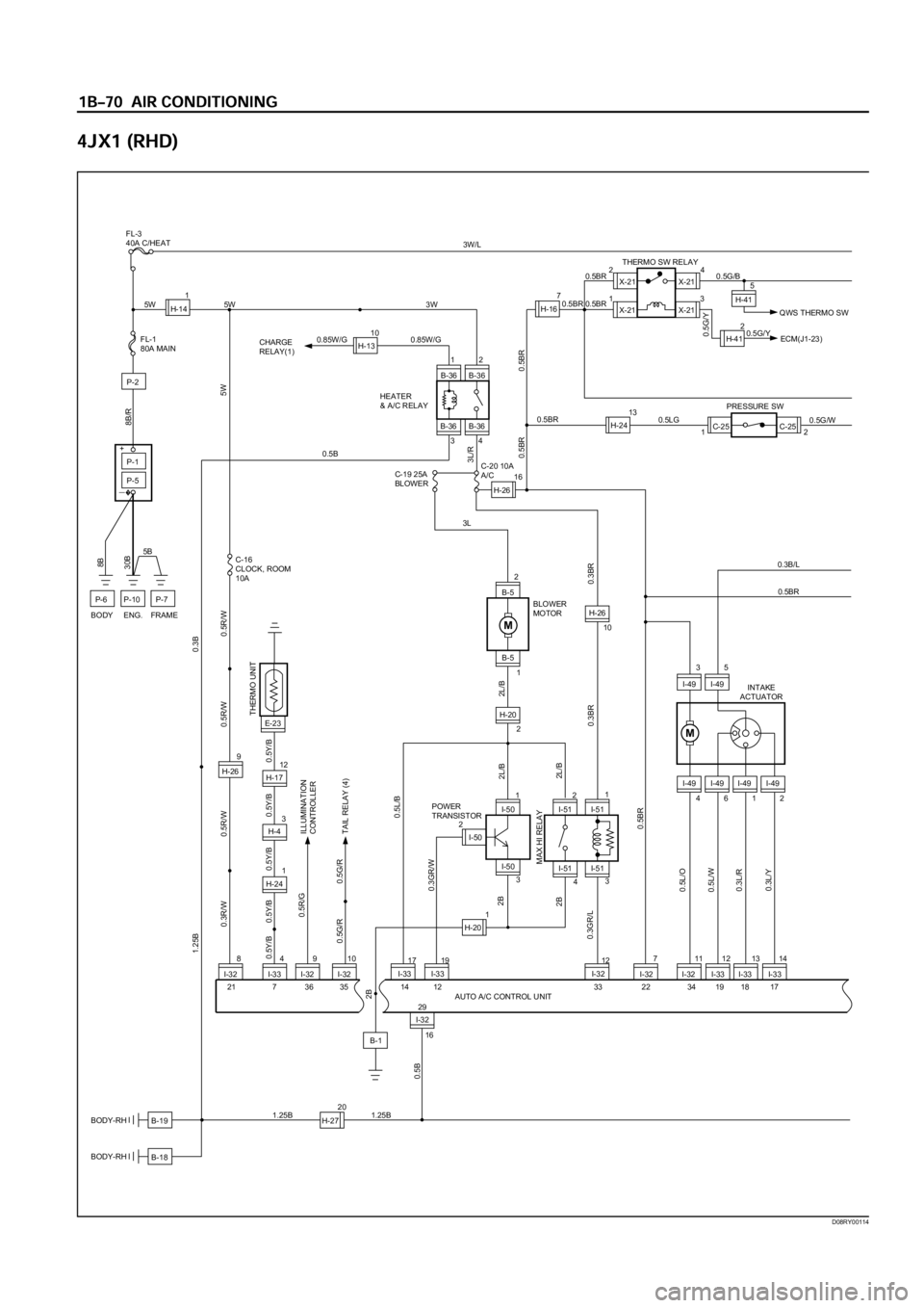
X-2124
13X-21
X-21THERMO SW RELAY
0.5BR 0.5BR
0.5G/Y
QWS THERMO SW 0.5G/BX-21
B-19
B-18
BODY-RH
BODY-RH
I-32 I-33I-32 I-32 I-33 I-33
84
I-329I-32107111213
12
B-36 B-36
B-36 B-3634
9
H-26
5W 3W
5W
3L/R
C-16
CLOCK, ROOM
BODY ENG. FRAME10A
0.5Y/B 0.5Y/B 0.5Y/B
0.5R/G
0.5G/R 0.5G/RILLUMINATION
CONTROLLER
TAIL RELAY (4) 0.5R/W 0.3R/W0.5R/W 0.5R/W
0.5BR 0.5BR
0.5BR
HEATER
& A/C RELAY CHARGE
RELAY(1)
P-1
P-5
P-2
P-7P-10P-6
5B30B8B
8B/R
FL-1
80A MAIN
+
�ー
AUTO A/C CONTROL UNIT
I-32
H-271.25B
0.5B
20
1.25B
I-3314
I-49
4612
M
I-49 I-49 I-49
I-493
5
I-49
16
0.5L/O
0.5L/W
0.3L/R
0.3L/Y
0.3B/L
1.25B0.3B
0.5BR
C-25C-25
2 1
H-26160.5G/W 0.5LGPRESSURE SW
INTAKE
ACTUATOR
H-141
H-1310
0.85W/G 0.85W/G
5W
0.5B
0.5BR
H-167
3
H-40.5Y/B 0.5Y/B
12
H-17
1
H-24
0.5BR
3W/LFL-3
40A C/HEAT
2H-410.5G/Y
ECM(J1-23)
H-2413
5
H-41
E-23THERMO UNIT
12
I-32
3L
2L/B 2L/B
C-19 25A
BLOWER
BLOWER
MOTOR C-20 10A
A/C
I-50 2
2B 2B
0.3GR/W0.5L/B
0.3BR 0.3BR 2L/B 2B
19
I-33
33 22 34 19 18 17 12
0.3GR/LMAX HI RELAY
POWER
TRANSISTOR
I-51
3
H-26
10
I-51
4I-50
3
I-512I-501I-511
B-52
B-5
1
H-20
2
17
I-33
14 35 36 7 21
29
H-201
M
B-1
D08RY00114