1998 OPEL FRONTERA ignition
[x] Cancel search: ignitionPage 1139 of 6000
6E–22
ENGINE DRIVEABILITY AND EMISSIONS
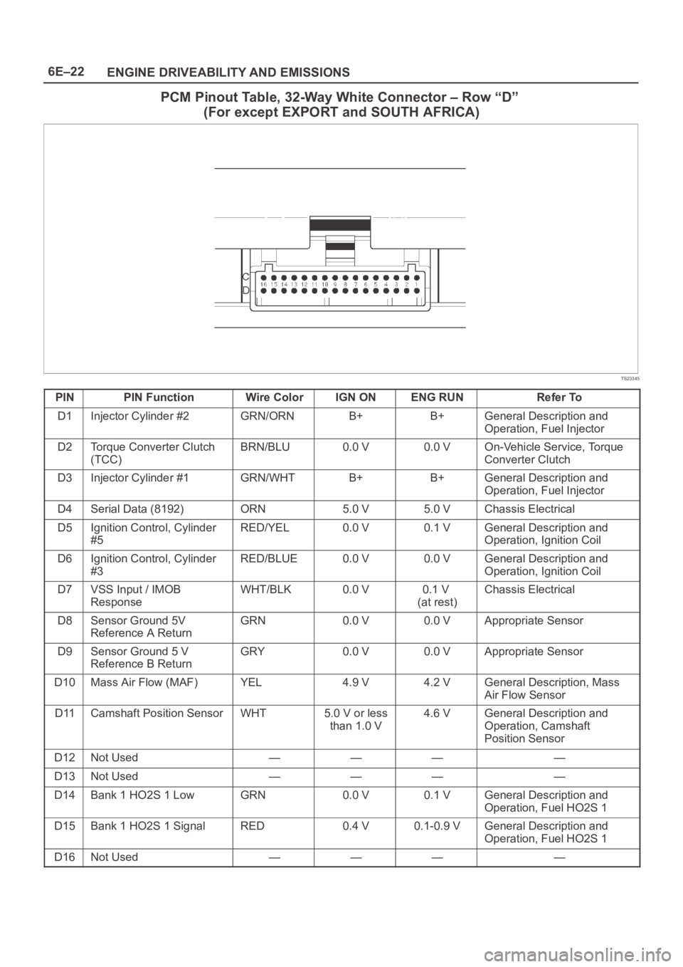
PCM Pinout Table, 32-Way White Connector – Row “D”
(For except EXPORT and SOUTH AFRICA)
TS23345
PINPIN FunctionWire ColorIGN ONENG RUNRefer To
D1Injector Cylinder #2GRN/ORNB+B+General Description and
Operation, Fuel Injector
D2Torque Converter Clutch
(TCC)BRN/BLU0.0 V0.0 VOn-Vehicle Service, Torque
Converter Clutch
D3Injector Cylinder #1GRN/WHTB+B+General Description and
Operation, Fuel Injector
D4Serial Data (8192)ORN5.0 V5.0 VChassis Electrical
D5Ignition Control, Cylinder
#5RED/YEL0.0 V0.1 VGeneral Description and
Operation, Ignition Coil
D6Ignition Control, Cylinder
#3RED/BLUE0.0 V0.0 VGeneral Description and
Operation, Ignition Coil
D7VSS Input / IMOB
ResponseWHT/BLK0.0 V0.1 V
(at rest)Chassis Electrical
D8Sensor Ground 5V
Reference A ReturnGRN0.0 V0.0 VAppropriate Sensor
D9Sensor Ground 5 V
Reference B ReturnGRY0.0 V0.0 VAppropriate Sensor
D10Mass Air Flow (MAF)YEL4.9 V4.2 VGeneral Description, Mass
Air Flow Sensor
D11Camshaft Position SensorWHT5.0 V or less
than 1.0 V4.6 VGeneral Description and
Operation, Camshaft
Position Sensor
D12Not Used————
D13Not Used————
D14Bank 1 HO2S 1 LowGRN0.0 V0.1 VGeneral Description and
Operation, Fuel HO2S 1
D15Bank 1 HO2S 1 SignalRED0.4 V0.1-0.9 VGeneral Description and
Operation, Fuel HO2S 1
D16Not Used————
Page 1140 of 6000
6E–23 ENGINE DRIVEABILITY AND EMISSIONS
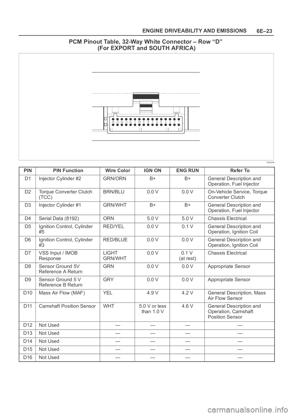
PCM Pinout Table, 32-Way White Connector – Row “D”
(For EXPORT and SOUTH AFRICA)
TS23345
PINPIN FunctionWire ColorIGN ONENG RUNRefer To
D1Injector Cylinder #2GRN/ORNB+B+General Description and
Operation, Fuel Injector
D2Torque Converter Clutch
(TCC)BRN/BLU0.0 V0.0 VOn-Vehicle Service, Torque
Converter Clutch
D3Injector Cylinder #1GRN/WHTB+B+General Description and
Operation, Fuel Injector
D4Serial Data (8192)ORN5.0 V5.0 VChassis Electrical
D5Ignition Control, Cylinder
#5RED/YEL0.0 V0.1 VGeneral Description and
Operation, Ignition Coil
D6Ignition Control, Cylinder
#3RED/BLUE0.0 V0.0 VGeneral Description and
Operation, Ignition Coil
D7VSS Input / IMOB
ResponseLIGHT
GRN/WHT0.0 V0.1 V
(at rest)Chassis Electrical
D8Sensor Ground 5V
Reference A ReturnGRN0.0 V0.0 VAppropriate Sensor
D9Sensor Ground 5 V
Reference B ReturnGRY0.0 V0.0 VAppropriate Sensor
D10Mass Air Flow (MAF)YEL4.9 V4.2 VGeneral Description, Mass
Air Flow Sensor
D11Camshaft Position SensorWHT5.0 V or less
than 1.0 V4.6 VGeneral Description and
Operation, Camshaft
Position Sensor
D12Not Used————
D13Not Used————
D14Not Used————
D15Not Used————
D16Not Used————
Page 1142 of 6000
6E–25 ENGINE DRIVEABILITY AND EMISSIONS
PINRefer To ENG RUN IGN ON Wire Color PIN Function
E15A/C RequestGRN/ORN0.0 V0.0 VElectric Cooling Fans
E16Ignition Feed (1 of 2 F16)RED/BLUB+B+—
Page 1143 of 6000
6E–26
ENGINE DRIVEABILITY AND EMISSIONS
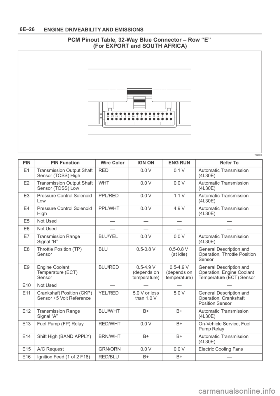
PCM Pinout Table, 32-Way Blue Connector – Row “E”
(For EXPORT and SOUTH AFRICA)
TS23346
PINPIN FunctionWire ColorIGN ONENG RUNRefer To
E1Transmission Output Shaft
Sensor (TOSS) HighRED0.0 V0.1 VAutomatic Transmission
(4L30E)
E2Transmission Output Shaft
Sensor (TOSS) LowWHT0.0 V0.0 VAutomatic Transmission
(4L30E)
E3Pressure Control Solenoid
LowPPL/RED0.0 V1.1 VAutomatic Transmission
(4L30E)
E4Pressure Control Solenoid
HighPPL/WHT0.0 V4.9 VAutomatic Transmission
(4L30E)
E5Not Used————
E6Not Used————
E7Transmission Range
Signal “B”BLU/YEL0.0 V0.0 VAutomatic Transmission
(4L30E)
E8Throttle Position (TP)
SensorBLU0.5-0.8 V0.5-0.8 V
(at idle)General Description and
Operation, Throttle Position
Sensor
E9Engine Coolant
Temperature (ECT)
SensorBLU/RED0.5-4.9 V
(depends on
temperature)0.5-4.9 V
(depends on
temperature)General Description and
Operation, Engine Coolant
Temperature (ECT) Sensor
E10Not Used————
E11Crankshaft Position (CKP)
Sensor +5 Volt ReferenceYEL/RED5.0 V or less
than 1.0 V5.0 VGeneral Description and
Operation, Crankshaft
Position Sensor
E12Transmission Range
Signal “A”BLU/WHTB+B+Automatic Transmission
(4L30E)
E13Fuel Pump (FP) RelayRED/WHT0.0 VB+On-Vehicle Service, Fuel
Pump Relay
E14Shift High (BAND APPLY)BRN/WHTB+B+Automatic Transmission
(4L30E)
E15A/C RequestGRN/ORN0.0 V0.0 VElectric Cooling Fans
E16Ignition Feed (1 of 2 F16)RED/BLUB+B+—
Page 1144 of 6000
6E–27 ENGINE DRIVEABILITY AND EMISSIONS
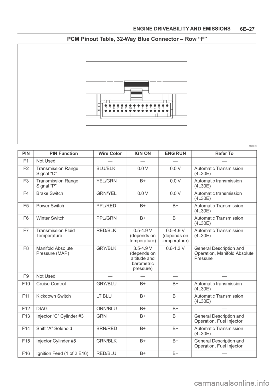
PCM Pinout Table, 32-Way Blue Connector – Row “F”
TS23346
PINPIN FunctionWire ColorIGN ONENG RUNRefer To
F1Not Used————
F2Transmission Range
Signal “C”BLU/BLK0.0 V0.0 VAutomatic Transmission
(4L30E)
F3Transmission Range
Signal “P”YEL/GRNB+0.0 VAutomatic transmission
(4L30E)
F4Brake SwitchGRN/YEL0.0 V0.0 VAutomatic transmission
(4L30E)
F5Power SwitchPPL/REDB+B+Automatic Transmission
(4L30E)
F6Winter SwitchPPL/GRNB+B+Automatic Transmission
(4L30E)
F7Transmission Fluid
TemperatureRED/BLK0.5-4.9 V
(depends on
temperature)0.5-4.9 V
(depends on
temperature)Automatic Transmission
(4L30E)
F8Manifold Absolute
Pressure (MAP)GRY/BLK3.5-4.9 V
(depends on
altitude and
barometric
pressure)0.6-1.3 VGeneral Description and
Operation, Manifold Absolute
Pressure
F9Not Used————
F10Cruise ControlGRY/BLUB+B+Automatic transmission
(4L30E)
F11Kickdown SwitchLT B L UB+B+Automatic Transmission
(4L30E)
F12DIAGORN/BLUB+B+—
F13Injector “C” Cylinder #3GRNB+B+General Description and
Operation, Fuel Injector
F14Shift “A” SolenoidBRN/REDB+B+Automatic Transmission
(4L30E)
F15Injector Cylinder #5GRN/BLKB+B+General Description and
Operation, Fuel Injector
F16Ignition Feed (1 of 2 E16)RED/BLUB+B+—
Page 1155 of 6000
6E–38
ENGINE DRIVEABILITY AND EMISSIONS
General Service Information
OBD Serviceablity Issues
The list of non-vehicle faults that could affect the
performance of the OBD system has been compiled.
These non-vehicle faults vary from environmental
conditions to the quality of fuel used.
The illumination of the MIL (“Check Engine” lamp) due to
a non-vehicle fault could lead to misdiagnosis of the
vehicle, increased warranty expense and customer
dissatisfaction. The following list of non-vehicle faults
does not include every possible fault and may not apply
equally to all product lines.
Fuel Quality
Using fuel with the wrong octane rating for your vehicle
may cause driveability problems. Many of the major fuel
companies advertise that using “premium” gasoline will
improve the performance of your vehicle. Most premium
fuels use alcohol to increase the octane rating of the fuel.
Although alcohol-enhanced fuels may raise the octane
rating, the fuel’s ability to turn into vapor in cold
temperatures deteriorates. This may affect the starting
ability and cold driveability of the engine.
Low fuel levels can lead to fuel starvation, lean engine
operation, and eventually engine misfire.
Non-OEM Parts
All of the OBD diagnostics have been calibrated to run
with OEM parts. Something as simple as a
high-performance exhaust system that affects exhaust
system back pressure could potentially interfere with the
operation of the EGR valve and thereby turn on the MIL
(“Check Engine” lamp). Small leaks in the exhaust
system near the post catalyst oxygen sensor can also
cause the MIL (“Check Engine” lamp) to turn on.
Aftermarket electronics, such as cellular phones,
stereos, and anti-theft devices, may radiate EMI into the
control system if they are improperly installed. This may
cause a false sensor reading and turn on the MIL (“Check
Engine” lamp).
Environment
Temporary environmental conditions, such as localized
flooding, will have an effect on the vehicle ignition system.
If the ignition system is rain-soaked, it can temporarily
cause engine misfire and turn on the MIL (“Check Engine”
lamp).
Poor Vehicle Maintenance
The sensitivity of OBD diagnostics will cause the MIL
(“Check Engine” lamp) to turn on if the vehicle is not
maintained properly. Restricted air filters, fuel filters, and
crankcase deposits due to lack of oil changes or improper
oil viscosity can trigger actual vehicle faults that were not
previously monitored prior to OBD. Poor vehicle
maintenance can not be classified as a “non-vehicle
fault”, but with the sensitivity of OBD diagnostics, vehicle
maintenance schedules must be more closely followed.Related System Faults
Many of the OBD system diagnostics will not run if the
PCM detects a fault on a related system or component.
One example would be that if the PCM detected a Misfire
fault, the diagnostics on the catalytic converter would be
suspended until Misfire fault was repaired. If the Misfire
fault was severe enough, the catalytic converter could be
damaged due to overheating and would never set a
Catalyst DTC until the Misfire fault was repaired and the
Catalyst diagnostic was allowed to run to completion. If
this happens, the customer may have to make two trips to
the dealership in order to repair the vehicle.
Maintenance Schedule
Refer to the Maintenance Schedule.
Visual / Physical Engine Compartment
Inspection
Perform a careful visual and physical engine
compartment inspection when performing any diagnostic
procedure or diagnosing the cause of an emission test
failure. This can often lead to repairing a problem without
further steps. Use the following guidelines when
performing a visual/physical inspection:
Inspect all vacuum hoses for punches, cuts,
disconnects, and correct routing.
Inspect hoses that are difficult to see behind other
components.
Inspect all wires in the engine compartment for proper
connections, burned or chafed spots, pinched wires,
contact with sharp edges or contact with hot exhaust
manifolds or pipes.
Basic Knowledge of Tools Required
NOTE: Lack of basic knowledge of this powertrain when
performing diagnostic procedures could result in an
incorrect diagnosis or damage to powertrain
components. Do not attempt to diagnose a powertrain
problem without this basic knowledge.
A basic understanding of hand tools is necessary to effec-
tively use this section of the Service Manual.
Serial Data Communications
Class II Serial Data Communications
This vehicle utilizes the “Class II” communication system.
Each bit of information can have one of two lengths: long
or short. This allows vehicle wiring to be reduced by
transmitting and receiving multiple signals over a single
wire. The messages carried on Class II data streams are
also prioritized. If two messages attempt to establish
communications on the data line at the same time, only
the message with higher priority will continue. The device
with the lower priority message must wait. The most
significant result of this regulation is that it provides Tech 2
manufacturers with the capability to access data from any
make or model vehicle that is sold.
Page 1156 of 6000
6E–39 ENGINE DRIVEABILITY AND EMISSIONS
The data displayed on the other Tech 2 will appear the
same, with some exceptions. Some Tech 2s will only be
able to display certain vehicle parameters as values that
are a coded representation of the true or actual value. For
more information on this system of coding, refer to
Decimal/Binary/Hexadecimal Conversions. On this
vehicle Tech 2 displays the actual values for vehicle
parameters. It will not be necessary to perform any
conversions from coded values to actual values.
On-Board Diagnostic (OBD)
On-Board Diagnostic Tests
A diagnostic test is a series of steps, the result of which is
a pass or fail reported to the diagnostic executive. When
a diagnostic test reports a pass result, the diagnostic
executive records the following data:
The diagnostic test has been completed since the last
ignition cycle.
The diagnostic test has passed during the current
ignition cycle.
The fault identified by the diagnostic test is not
currently active.
W h e n a d i a g n o s t i c t e s t r e p o r t s a fail result, the diagnostic
executive records the following data:
The diagnostic test has been completed since the last
ignition cycle.
The fault identified by the diagnostic test is currently
active.
The fault has been active during this ignition cycle.
The operating conditions at the time of the failure.
Remember, a fuel trim DTC may be triggered by a list of
vehicle faults. Make use of all information available (other
DTCs stored, rich or lean condition, etc.) when
diagnosing a fuel trim fault.
Comprehensive Component Monitor
Diagnostic Operation
Input Components:
Input components are monitored for circuit continuity and
out-of-range values. This includes rationality checking.
Rationality checking refers to indicating a fault when the
signal from a sensor does not seem reasonable, i.e.
Throttle Position (TP) sensor that indicates high throttle
position at low engine loads or MAP voltage. Input
components may include, but are not limited to the
following sensors:
Vehicle Speed Sensor (VSS)
Crankshaft Position (CKP) sensor
Knock Sensor (KS)
Throttle Position (TP) sensor
Engine Coolant Temperature (ECT) sensor
Camshaft Position (CMP) sensor
Manifold Absolute Pressure (MAP) sensor
Mass Air Flow (MAF) sensorIn addition to the circuit continuity and rationality check,
the ECT sensor is monitored for its ability to achieve a
steady state temperature to enable closed loop fuel
control.
Output Components:
Output components are diagnosed for proper response to
control module commands. Components where
functional monitoring is not feasible will be monitored for
circuit continuity and out-of-range values if applicable.
Output components to be monitored include, but are not
limited to, the following circuits:
Idle Air Control (IAC) Motor
Electronic Transmission controls
A/C relays
Cooling fan relay
VSS output
MIL control
Cruise control inhibit
Refer to PCM and Sensors in General Descriptions.
Passive and Active Diagnostic Tests
A passive test is a diagnostic test which simply monitors a
vehicle system or component. Conversely, an active test,
actually takes some sort of action when performing
diagnostic functions, often in response to a failed passive
test. For example, the EGR diagnostic active test will
force the EGR valve open during closed throttle decel
and/or force the EGR valve closed during a steady state.
Either action should result in a change in manifold
pressure.
Intrusive Diagnostic Tests
This is any on-board test run by the Diagnostic
Management System which may have an effect on
vehicle performance or emission levels.
Warm-Up Cycle
A warm-up cycle means that engine at temperature must
reach a minimum of 70
C (160F) and rise at least 22C
(40
F) over the course of a trip.
Freeze Frame
Freeze Frame is an element of the Diagnostic
Management System which stores various vehicle
information at the moment an emissions-related fault is
stored in memory and when the MIL is commanded on.
These data can help to identify the cause of a fault. Refer
to
Storing And Erasing Freeze Fame Data for more
detailed information.
Failure Records
Failure Records data is an enhancement of the OBD
Freeze Frame feature. Failure Records store the same
vehicle information as does Freeze Frame, but it will store
that information for any fault which is stored in on-board
memory, while Freeze Frame stores information only for
emission-related faults that command the MIL on.
Page 1159 of 6000
6E–42
ENGINE DRIVEABILITY AND EMISSIONS
Intermittent Malfunction Indicator Lamp
In the case of an “intermittent” fault, the MIL (“Check
Engine” lamp) may illuminate and then (after three trips)
go “OFF”. However, the corresponding diagnostic trouble
code will be stored in the memory. When unexpected
diagnostic trouble codes appear, check for an intermittent
malfunction.
A diagnostic trouble code may reset. Consult the
“Diagnostic Aids” associated with the diagnostic trouble
code. A physical inspection of the applicable sub-system
most often will resolve the problem.
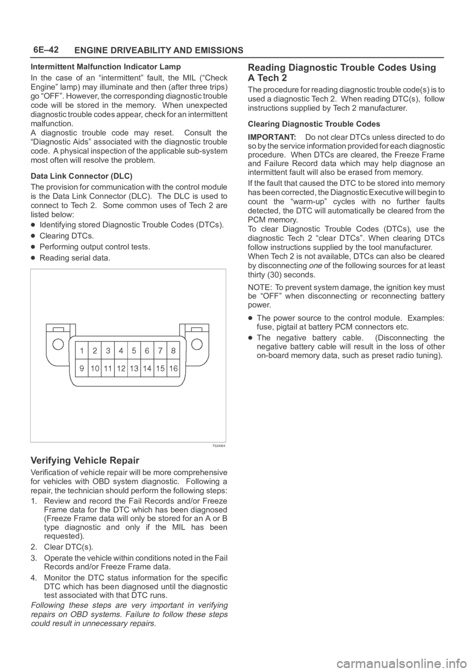
Data Link Connector (DLC)
The provision for communication with the control module
is the Data Link Connector (DLC). The DLC is used to
connect to Tech 2. Some common uses of Tech 2 are
listed below:
Identifying stored Diagnostic Trouble Codes (DTCs).
Clearing DTCs.
Performing output control tests.
Reading serial data.
TS24064
Verifying Vehicle Repair
Verification of vehicle repair will be more comprehensive
for vehicles with OBD system diagnostic. Following a
repair, the technician should perform the following steps:
1. Review and record the Fail Records and/or Freeze
Frame data for the DTC which has been diagnosed
(Freeze Frame data will only be stored for an A or B
type diagnostic and only if the MIL has been
requested).
2. Clear DTC(s).
3. Operate the vehicle within conditions noted in the Fail
Records and/or Freeze Frame data.
4. Monitor the DTC status information for the specific
DTC which has been diagnosed until the diagnostic
test associated with that DTC runs.
Following these steps are very important in verifying
repairs on OBD systems. Failure to follow these steps
could result in unnecessary repairs.
Reading Diagnostic Trouble Codes Using
A Tech 2
The procedure for reading diagnostic trouble code(s) is to
used a diagnostic Tech 2. When reading DTC(s), follow
instructions supplied by Tech 2 manufacturer.
Clearing Diagnostic Trouble Codes
IMPORTANT:Do not clear DTCs unless directed to do
so by the service information provided for each diagnostic
procedure. When DTCs are cleared, the Freeze Frame
and Failure Record data which may help diagnose an
intermittent fault will also be erased from memory.
If the fault that caused the DTC to be stored into memory
has been corrected, the Diagnostic Executive will begin to
count the “warm-up” cycles with no further faults
detected, the DTC will automatically be cleared from the
PCM memory.
To clear Diagnostic Trouble Codes (DTCs), use the
diagnostic Tech 2 “clear DTCs”. When clearing DTCs
follow instructions supplied by the tool manufacturer.
When Tech 2 is not available, DTCs can also be cleared
by disconnecting
one of the following sources for at least
thirty (30) seconds.
NOTE: To prevent system damage, the ignition key must
be “OFF” when disconnecting or reconnecting battery
power.
The power source to the control module. Examples:
fuse, pigtail at battery PCM connectors etc.
The negative battery cable. (Disconnecting the
negative battery cable will result in the loss of other
on-board memory data, such as preset radio tuning).