Page 5029 of 6000

6G–10
ENGINE LUBRICATION
Oil Pump
Removal
1. Disconnect battery ground cable.
2. Drain engine oil.
3. Remove crankcase assembly.
Refer to removal procedure for Oil Pan and
Crankcase in this manual.
4. Remove crankshaft pulley.
Refer to removal procedure for Crankshaft Pulley in
this manual.
5. Remove timing belt.
Refer to removal procedure for Timing Belt in this
manual.
6. Remove timing pulley from crankshaft.
7. Remove four fixing bolts from oil filter assembly.
8. Remove oil strainer fixing bolts, remove oil strainer
assembly with O-ring.
9. Remove three bolts from oil pipe and O-ring.
10. Remove eight oil pump fixing bolts, then oil pump
assembly.
11. Remove sealant from mounting surface of oil pump
assembly, cylinder block and take care not to damage
mounting surfaces of oil pump and cylinder block.
Installation
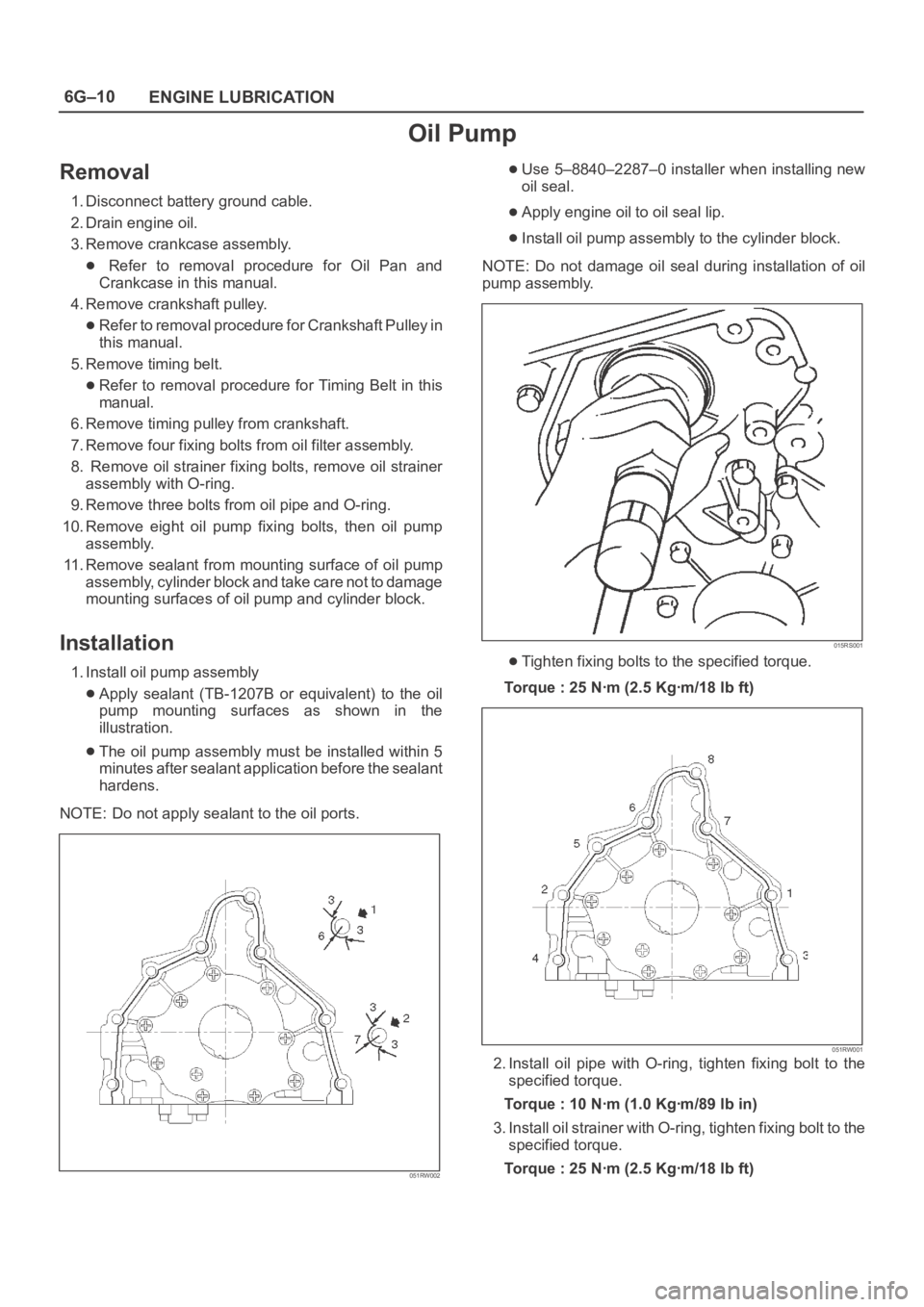
1. Install oil pump assembly
Apply sealant (TB-1207B or equivalent) to the oil
pump mounting surfaces as shown in the
illustration.
The oil pump assembly must be installed within 5
minutes after sealant application before the sealant
hardens.
NOTE: Do not apply sealant to the oil ports.
051RW002
Use 5–8840–2287–0 installer when installing new
oil seal.
Apply engine oil to oil seal lip.
Install oil pump assembly to the cylinder block.
NOTE: Do not damage oil seal during installation of oil
pump assembly.
015RS001
Tighten fixing bolts to the specified torque.
Torque : 25 Nꞏm (2.5 Kgꞏm/18 lb ft)
051RW001
2. Install oil pipe with O-ring, tighten fixing bolt to the
specified torque.
Torque : 10 Nꞏm (1.0 Kgꞏm/89 lb in)
3. Install oil strainer with O-ring, tighten fixing bolt to the
specified torque.
Torque : 25 Nꞏm (2.5 Kgꞏm/18 lb ft)
Page 5030 of 6000
6G–11 ENGINE LUBRICATION
4. Install oil filter assembly and tighten bolts to the
specified torque.
Torque : 25 Nꞏm (2.5 Kgꞏm/18 lb ft)
050RW001
Legend
(1) Oil Pump
(2) Oil Filter
(3) Oil Gallery
(4) From Oil Filter
(5) To Oil Filter
5. Install timing pulley on crankshaft.
Install timing belt.
Refer to installation procedure for Timing Belt in this
manual.
6. Install crankshaft pulley.
Refer to install procedure for Crankshaft Pulley in
this manual.
7. Install crankcase assembly.
Refer to installation procedure for Oil Pan and
Crankcase in this manual.
8. Refill engine oil until full level on engine oil dipstick.
Page 5031 of 6000
6G–12
ENGINE LUBRICATION
Oil Pump Oil Seal
Removal
1. Disconnect battery ground cable.
2. Drain engine oil.
3. Remove crankshaft pulley.
Refer to removal procedure for Crankshaft Pulley in
this manual.
4. Remove timing belt.
Refer to removal procedure for Timing Belt in this
manual.
5. Remove timing pulley from crankshaft.
6. Remove oil pump oil seal using a sealer puller.
NOTE: Take care not to damage sealing surfaces of oil
pump and crankshaft when removing oil seal.
Installation
1. Install oil pump oil seal, apply engine oil to oil seal lip,
then install oil seal using 5–8840–2287–0 installer.
015RS001
2. Install timing pulley to crankshaft.
3. Install timing belt.
Refer to installation procedure for Timing Belt in this
manual.
4. Install crankshaft pulley.
Refer to installation procedure for Crankshaft
Pulley in this manual.
5. Refill engine oil until full level.
Page 5032 of 6000
6G–13 ENGINE LUBRICATION
Oil Filter
Removal
1. Disconnect battery ground cable.
2. Drain engine oil.
3. Remove oil filter using 5-8840-0203-0 filter wrench.
Installation
1. Clean filter fitting surface and apply small amount of
engine oil to sealing surface.
2. Install oil filter cartridge by hand until it comes in
contact with sealing surface then rotate additional 2/3
turn to tighten using 5-8840-0203-0 filter wrench.
050RW001
Legend
(1) Oil Pump
(2) Oil Filter
(3) Oil Gallery
(4) From Filter
(5) To Filter
3. Fill engine oil until full level on dipstick.
4. Reconnect battery ground cable.
Page 5033 of 6000
6G–14
ENGINE LUBRICATION
Main Data and Specification
General Specification
ItemSpecificationsItem6VD16VE1
Oil capacity5.3 liters
Torque Specifications
Crankcase, Oil pan, Timing belt tensioner, Timing
pulley, timing belt cover, Oil pump, Oil gallery, Oil
strainer Nꞏm (Kgꞏm/lb ft)
E06RW045
Page 5034 of 6000
6G–15 ENGINE LUBRICATION
Special Tool
ILLUSTRATIONTOOL NO.
TOOL NAME
5–8840–2287–0
(J–39202)
Installer; Oil pump oil
seal
5–8840–2153–0
(J–37228)
Seal cutter
5–8840–2005–0
(J–29107)
Universal pitman arm
puller
5–8840–0203–0
(J–36390)
Wrench; Oil filter
Page 5274 of 6000

ENGINE MECHANICAL 6A – 1
ENGINE
ENGINE MECHANICAL
CONTENTS
General Description . . . . . . . . . . . . . . . . . . . . 6A–2
Service Information . . . . . . . . . . . . . . . . . . . . 6A–3
Service Standard . . . . . . . . . . . . . . . . . . . . . . 6A–6
Servicing . . . . . . . . . . . . . . . . . . . . . . . . . . . . 6A–9
Tightening Torque . . . . . . . . . . . . . . . . . . . . . 6A–14
Special Tools . . . . . . . . . . . . . . . . . . . . . . . . . 6A–23
Engine Assembly . . . . . . . . . . . . . . . . . . . . . . 6A–26
Engine Mount (RH) . . . . . . . . . . . . . . . . . . . . 6A–28
Engine Mount (LH). . . . . . . . . . . . . . . . . . . . . 6A–29
Intercooler . . . . . . . . . . . . . . . . . . . . . . . . . . . 6A–30
Cylinder Head Cover . . . . . . . . . . . . . . . . . . . 6A–31
Intake Manifold . . . . . . . . . . . . . . . . . . . . . . . 6A–33
Exhaust Manifold . . . . . . . . . . . . . . . . . . . . . . 6A–34
Turbocharger . . . . . . . . . . . . . . . . . . . . . . . . . 6A–35Cylinder Head . . . . . . . . . . . . . . . . . . . . . . . . 6A–37
Cylinder Head Gasket . . . . . . . . . . . . . . . . . . 6A–39
Camshaft . . . . . . . . . . . . . . . . . . . . . . . . . . . . 6A–43
Timing Gear . . . . . . . . . . . . . . . . . . . . . . . . . . 6A–48
Valve Stem Seal, Valve Spring and Adjuster . . 6A–56
Valve Clearance Adjustment. . . . . . . . . . . . . . 6A–63
Oil Rail and Injector . . . . . . . . . . . . . . . . . . . . 6A–65
Crank Case . . . . . . . . . . . . . . . . . . . . . . . . . . 6A–68
Crankshaft . . . . . . . . . . . . . . . . . . . . . . . . . . . 6A–70
Piston and Connecting Rod . . . . . . . . . . . . . . 6A–80
Cylinder Block . . . . . . . . . . . . . . . . . . . . . . . . 6A–88
Oil Pump Assembly . . . . . . . . . . . . . . . . . . . . 6A–94
Oil Filter Cartridge . . . . . . . . . . . . . . . . . . . . . 6A–95
Oil Cooler . . . . . . . . . . . . . . . . . . . . . . . . . . . 6A–95
Page 5275 of 6000

6A – 2 ENGINE MECHANICAL
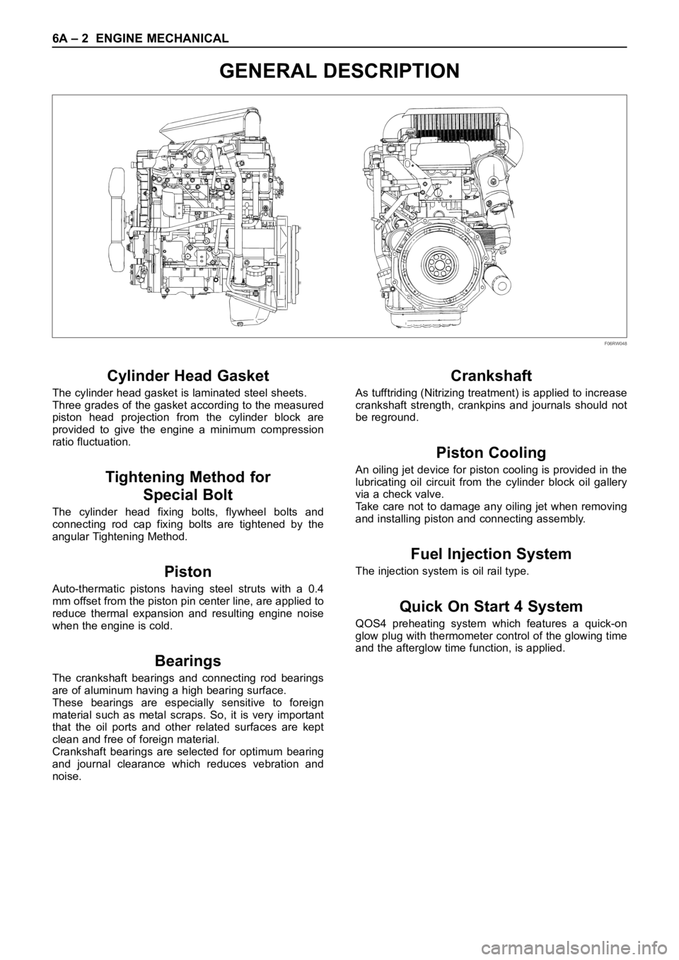
GENERAL DESCRIPTION
Cylinder Head Gasket
The cylinder head gasket is laminated steel sheets.
Three grades of the gasket according to the measured
piston head projection from the cylinder block are
provided to give the engine a minimum compression
ratio fluctuation.
Tightening Method for
Special Bolt
The cylinder head fixing bolts, flywheel bolts and
connecting rod cap fixing bolts are tightened by the
angular Tightening Method.
Piston
Auto-thermatic pistons having steel struts with a 0.4
mm offset from the piston pin center line, are applied to
reduce thermal expansion and resulting engine noise
when the engine is cold.
Bearings
The crankshaft bearings and connecting rod bearings
are of aluminum having a high bearing surface.
These bearings are especially sensitive to foreign
material such as metal scraps. So, it is very important
that the oil ports and other related surfaces are kept
clean and free of foreign material.
Crankshaft bearings are selected for optimum bearing
and journal clearance which reduces vebration and
noise.
Crankshaft
As tufftriding (Nitrizing treatment) is applied to increase
crankshaft strength, crankpins and journals should not
be reground.
Piston Cooling
An oiling jet device for piston cooling is provided in the
lubricating oil circuit from the cylinder block oil gallery
via a check valve.
Take care not to damage any oiling jet when removing
and installing piston and connecting assembly.
Fuel Injection System
The injection system is oil rail type.
Quick On Start 4 System
QOS4 preheating system which features a quick-on
glow plug with thermometer control of the glowing time
and the afterglow time function, is applied.
F06RW048