1998 OPEL FRONTERA air condition
[x] Cancel search: air conditionPage 5354 of 6000
ENGINE MECHANICAL 6A – 81
DISASSEMBLY
1. Cylinder Head Assembly
1) Refer to “Cylinder head” in this manual.
2. Crank Case Assembly
1) Refer to “Crank Case” in this manual.
3. Connecting Rod Bearing Cap
4. Piston and Connecting Rod
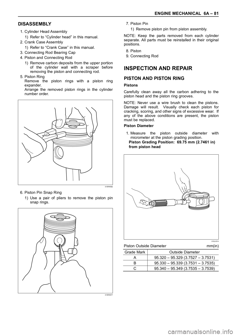
1) Remove carbon deposits from the upper portion
of the cylinder wall with a scraper before
removing the piston and connecting rod.
5. Piston Ring
Remove the piston rings with a piston ring
expander.
Arrange the removed piston rings in the cylinder
number order.
6. Piston Pin Snap Ring
1) Use a pair of pliers to remove the piston pin
snap rings.7. Piston Pin
1) Remove piston pin from piston assembly.
NOTE: Keep the parts removed from each cylinder
separate. All parts must be reinstalled in their original
positions.
8. Piston
9. Connecting Rod
INSPECTION AND REPAIR
PISTON AND PISTON RING
Pistons
Carefully clean away all the carbon adhering to the
piston head and the piston ring grooves.
NOTE: Never use a wire brush to clean the pistons.
Damage will result. Visually check each piston for
cracking, scoring, and other signs of excessive wear. If
any of the above conditions are present, the piston
must be replaced.
Piston Diameter
1. Measure the piston outside diameter with
micrometer at the piston grading position.
Piston Grading Position: 69.75 mm (2.7461 in)
from piston head
Piston Outside Diameter mm(in)
Grade Mark Outside Diameter
A 95.320 – 95.329 (3.7527 – 3.7531)
B 95.330 – 95.339 (3.7531 – 3.7535)
C 95.340 – 95.349 (3.7535 – 3.7539)
015RW082
015RW077
015LV014
Page 5374 of 6000

ENGINE COOLING 6B – 5
ENGINE COOLANT CHANGE
PROCEDURE
1. To change engine coolant, make sure that the
engine is cool.
WARNING:
When the coolant is heated to a high temperature,
be sure not to loosen or remove the radiator cap.
Otherwise you might get scalded by hot vapor or
boiling water. To open the radiator cap, put a piece
of thick cloth on the cap and loosen the cap slowly
to reduce the pressure once the coolant has
become cooler.
2. Open radiator cap and drain the cooling system by
loosening the drain valve on the radiator and on the
cylinder body.
NOTE: For best results it is suggested that the engine
cooling system be flushed at least once a year. It is
advisable to flush the interior of the cooling system
including the radiator before using anti-freeze
(ethylene-glycol based).
Replace damaged rubber hoses as the engine anti-
freeze coolant is liable to leak out even minor cracks.
Isuzu recommends using Isuzu genuine anti-freeze
(ethylene-glycol based) or equivalent, for the cooling
system and not add any inhibitors or additives.
CAUTION:
A failure to correctly fill the engine cooling system
in changing or topping off coolant may sometimes
cause the coolant to overflow from the filler neck
even before the engine and radiator are completely
full.
If the engine runs under this condition, shortage of
coolant may possibly result in engine overheating.
To avoid such trouble, the following precautions
should be taken in filling the system.
3. To refill engine coolant, pour coolant up to filler neck
using a filling hose which is smaller in outside
diameter than the filler neck. Otherwise air between
the filler neck and the filling hose will block entry,
preventing the system from completely filling up.
4. Keep a filling rate of 9 liter/min. or less. Filling over
this maximum rate may force air inside the engine
and radiator.
And also, the coolant overflow will increase, making
it difficult to determine whether or not the system is
completely full.
5. After filling the system full, pull out the filling hose
and check to see if air trapped in the system is
dislodged and the coolant level goes down. Should
the coolant level go down, repeat topping-off until
there is no more drop in the coolant level.
6. Directly after filling the radiator, fill the reservoir to
the maximum level.
7. Install and tighten radiator cap and start the engine.
After idling for 2 to 3 minutes, stop the engine and
reopen radiator cap. If the water level is lower,
replenish.WARNING:
When the coolant is heated to a high temperature,
be sure not to loosen or remove the radiator cap.
Otherwise you might get scalded by hot vapor or
boiling water. To open the radiator cap, put a piece
of thick cloth on the cap and loosen the cap slowly
to reduce the pressure once the coolant has
become cooler.
8. After tightening radiator cap, warm up the engine at
about 2,000 rpm.
Set heater adjustment to the highest temperature
position, and let the coolant circulate also into
heater water system.
9. Check to see the thermostat has opened by the
needle position of a water thermometer, conduct a
5-minute idle again and stop the engine.
10. When the engine has been cooled, check filler neck
for water level and replenish if required. Should
extreme shortage of coolant be found, check the
coolant system and reservoir tank hose for leakage.
11. Fill the coolant into the reservoir tank up to “MAX”
line.
Page 5402 of 6000
ENGINE FUEL 6C – 21
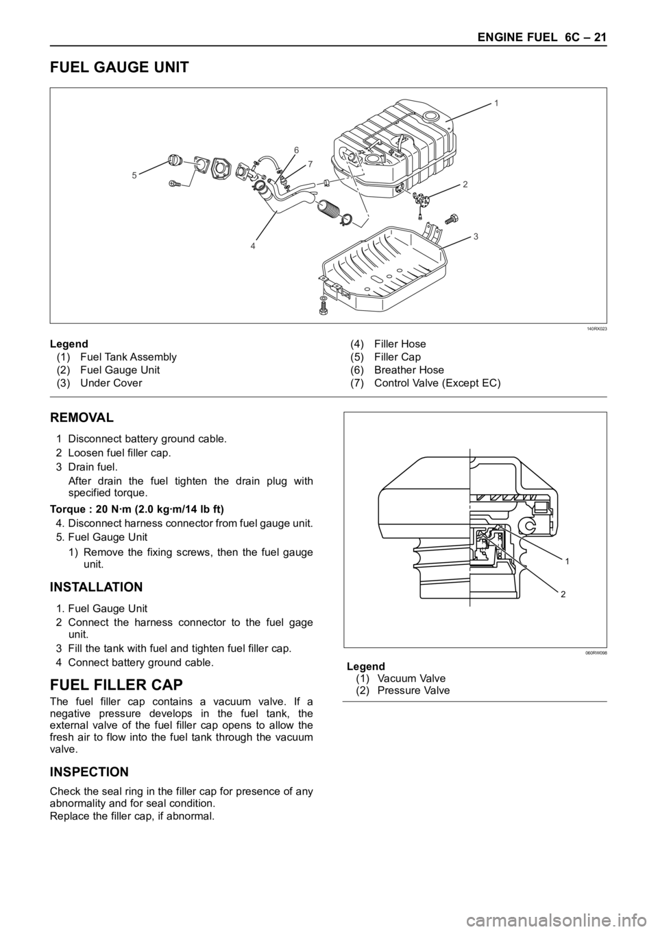
FUEL GAUGE UNIT
1
2
6
7
4
5
3
140RX023
REMOVAL
1 Disconnect battery ground cable.
2 Loosen fuel filler cap.
3 Drain fuel.
After drain the fuel tighten the drain plug with
specified torque.
Torque : 20 Nꞏm (2.0 kgꞏm/14 lb ft)
4. Disconnect harness connector from fuel gauge unit.
5. Fuel Gauge Unit
1) Remove the fixing screws, then the fuel gauge
unit.
INSTALLATION
1. Fuel Gauge Unit
2 Connect the harness connector to the fuel gage
unit.
3 Fill the tank with fuel and tighten fuel filler cap.
4 Connect battery ground cable.
FUEL FILLER CAP
The fuel filler cap contains a vacuum valve. If a
negative pressure develops in the fuel tank, the
external valve of the fuel filler cap opens to allow the
fresh air to flow into the fuel tank through the vacuum
valve.
INSPECTION
Check the seal ring in the filler cap for presence of any
abnormality and for seal condition.
Replace the filler cap, if abnormal.Legend
(1) Vacuum Valve
(2) Pressure Valve Legend
(1) Fuel Tank Assembly
(2) Fuel Gauge Unit
(3) Under Cover(4) Filler Hose
(5) Filler Cap
(6) Breather Hose
(7) Control Valve (Except EC)
1
2
060RW098
Page 5414 of 6000
ENGINE ELECTRICAL 6D – 11
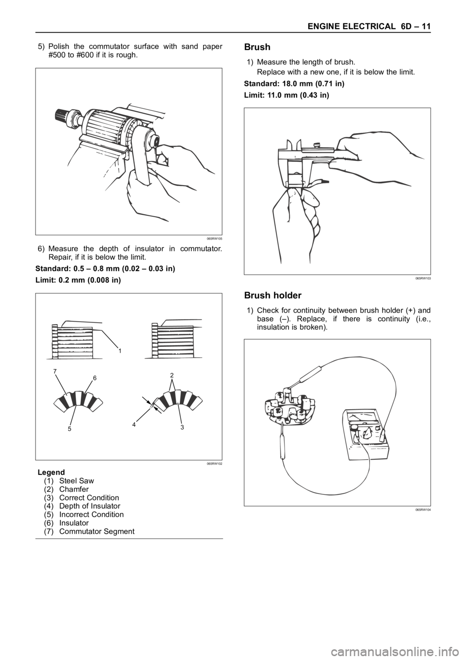
5) Polish the commutator surface with sand paper
#500 to #600 if it is rough.
6) Measure the depth of insulator in commutator.
Repair, if it is below the limit.
Standard: 0.5 – 0.8 mm (0.02 – 0.03 in)
Limit: 0.2 mm (0.008 in)
Legend
(1) Steel Saw
(2) Chamfer
(3) Correct Condition
(4) Depth of Insulator
(5) Incorrect Condition
(6) Insulator
(7) Commutator SegmentBrush
1) Measure the length of brush.
Replace with a new one, if it is below the limit.
Standard: 18.0 mm (0.71 in)
Limit: 11.0 mm (0.43 in)
Brush holder
1) Check for continuity between brush holder (+) and
base (–). Replace, if there is continuity (i.e.,
insulation is broken).
065RW105
1
6
53 42 7
065RW102
065RW103
065RW104
Page 5419 of 6000
6D – 16 ENGINE ELECTRICAL
DIAGNOSIS
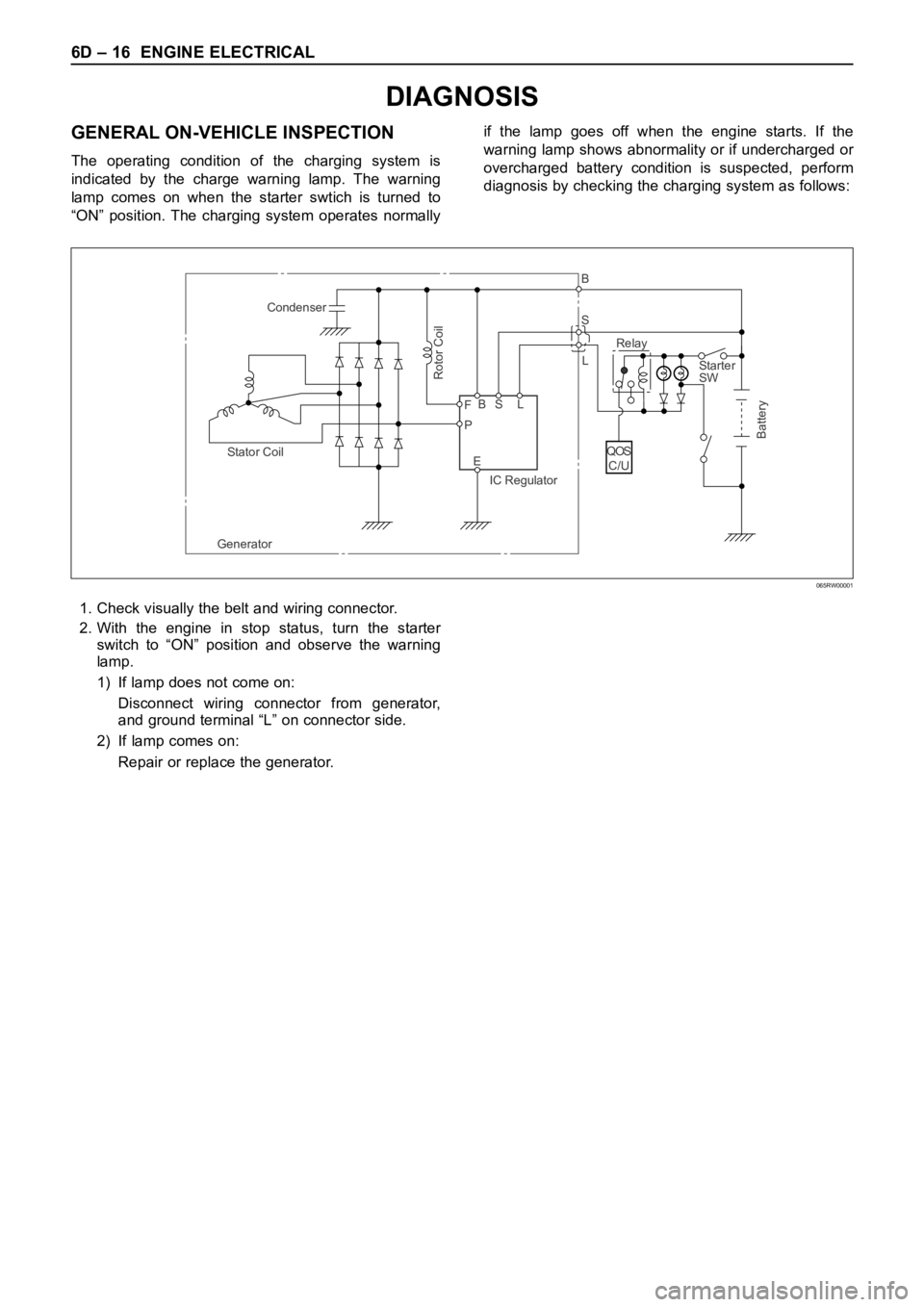
GENERAL ON-VEHICLE INSPECTION
The operating condition of the charging system is
indicated by the charge warning lamp. The warning
lamp comes on when the starter swtich is turned to
“ON” position. The charging system operates normallyif the lamp goes off when the engine starts. If the
warning lamp shows abnormality or if undercharged or
overcharged battery condition is suspected, perform
diagnosis by checking the charging system as follows:
Condenser
GeneratorStator Coil
IC RegulatorStarter
SW
Rotor Coil
Battery
P F
EBS LRelay B
S
L
QOS
C/U
065RW00001
1. Check visually the belt and wiring connector.
2. With the engine in stop status, turn the starter
switch to “ON” position and observe the warning
lamp.
1) If lamp does not come on:
Disconnect wiring connector from generator,
and ground terminal “L” on connector side.
2) If lamp comes on:
Repair or replace the generator.
Page 5430 of 6000
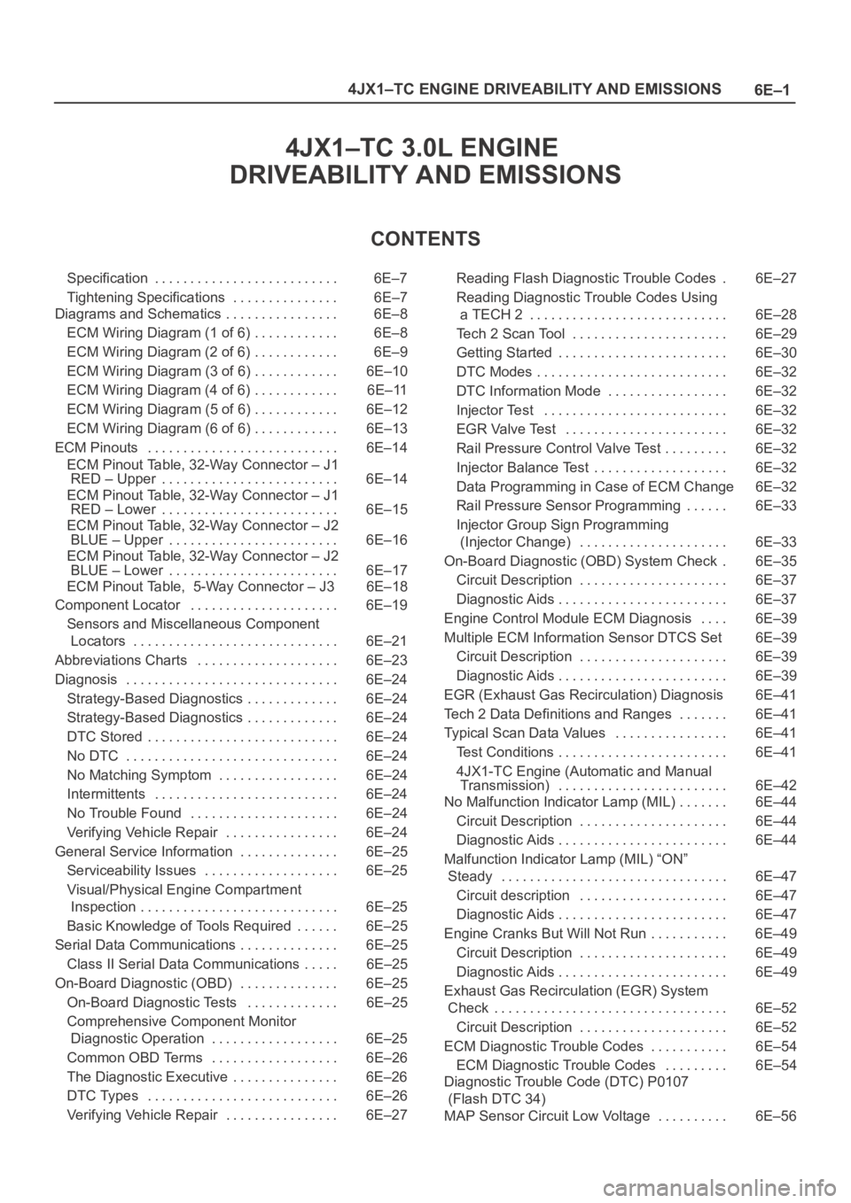
6E–1 4JX1–TC ENGINE DRIVEABILITY AND EMISSIONS
4JX1–TC 3.0L ENGINE
DRIVEABILITY AND EMISSIONS
CONTENTS
Specification 6E–7. . . . . . . . . . . . . . . . . . . . . . . . . .
Tightening Specifications 6E–7. . . . . . . . . . . . . . .
Diagrams and Schematics 6E–8. . . . . . . . . . . . . . . .
ECM Wiring Diagram (1 of 6) 6E–8. . . . . . . . . . . .
ECM Wiring Diagram (2 of 6) 6E–9. . . . . . . . . . . .
ECM Wiring Diagram (3 of 6) 6E–10. . . . . . . . . . . .
ECM Wiring Diagram (4 of 6) 6E–11. . . . . . . . . . . .
ECM Wiring Diagram (5 of 6) 6E–12. . . . . . . . . . . .
ECM Wiring Diagram (6 of 6) 6E–13. . . . . . . . . . . .
ECM Pinouts 6E–14. . . . . . . . . . . . . . . . . . . . . . . . . . .
ECM Pinout Table, 32-Way Connector – J1
RED – Upper 6E–14. . . . . . . . . . . . . . . . . . . . . . . . .
ECM Pinout Table, 32-Way Connector – J1
RED – Lower 6E–15. . . . . . . . . . . . . . . . . . . . . . . . .
ECM Pinout Table, 32-Way Connector – J2
BLUE – Upper 6E–16. . . . . . . . . . . . . . . . . . . . . . . .
ECM Pinout Table, 32-Way Connector – J2
BLUE – Lower 6E–17. . . . . . . . . . . . . . . . . . . . . . . .
ECM Pinout Table, 5-Way Connector – J3 6E–18
Component Locator 6E–19. . . . . . . . . . . . . . . . . . . . .
Sensors and Miscellaneous Component
Locators 6E–21. . . . . . . . . . . . . . . . . . . . . . . . . . . . .
Abbreviations Charts 6E–23. . . . . . . . . . . . . . . . . . . .
Diagnosis 6E–24. . . . . . . . . . . . . . . . . . . . . . . . . . . . . .
Strategy-Based Diagnostics 6E–24. . . . . . . . . . . . .
Strategy-Based Diagnostics 6E–24. . . . . . . . . . . . .
DTC Stored 6E–24. . . . . . . . . . . . . . . . . . . . . . . . . . .
No DTC 6E–24. . . . . . . . . . . . . . . . . . . . . . . . . . . . . .
No Matching Symptom 6E–24. . . . . . . . . . . . . . . . .
Intermittents 6E–24. . . . . . . . . . . . . . . . . . . . . . . . . .
No Trouble Found 6E–24. . . . . . . . . . . . . . . . . . . . .
Verifying Vehicle Repair 6E–24. . . . . . . . . . . . . . . .
General Service Information 6E–25. . . . . . . . . . . . . .
Serviceability Issues 6E–25. . . . . . . . . . . . . . . . . . .
Visual/Physical Engine Compartment
Inspection 6E–25. . . . . . . . . . . . . . . . . . . . . . . . . . . .
Basic Knowledge of Tools Required 6E–25. . . . . .
Serial Data Communications 6E–25. . . . . . . . . . . . . .
Class II Serial Data Communications 6E–25. . . . .
On-Board Diagnostic (OBD) 6E–25. . . . . . . . . . . . . .
On-Board Diagnostic Tests 6E–25. . . . . . . . . . . . .
Comprehensive Component Monitor
Diagnostic Operation 6E–25. . . . . . . . . . . . . . . . . .
Common OBD Terms 6E–26. . . . . . . . . . . . . . . . . .
The Diagnostic Executive 6E–26. . . . . . . . . . . . . . .
DTC Types 6E–26. . . . . . . . . . . . . . . . . . . . . . . . . . .
Verifying Vehicle Repair 6E–27. . . . . . . . . . . . . . . . Reading Flash Diagnostic Trouble Codes 6E–27.
Reading Diagnostic Trouble Codes Using
a TECH 2 6E–28. . . . . . . . . . . . . . . . . . . . . . . . . . . .
Tech 2 Scan Tool 6E–29. . . . . . . . . . . . . . . . . . . . . .
Getting Started 6E–30. . . . . . . . . . . . . . . . . . . . . . . .
DTC Modes 6E–32. . . . . . . . . . . . . . . . . . . . . . . . . . .
DTC Information Mode 6E–32. . . . . . . . . . . . . . . . .
Injector Test 6E–32. . . . . . . . . . . . . . . . . . . . . . . . . .
EGR Valve Test 6E–32. . . . . . . . . . . . . . . . . . . . . . .
Rail Pressure Control Valve Test 6E–32. . . . . . . . .
Injector Balance Test 6E–32. . . . . . . . . . . . . . . . . . .
Data Programming in Case of ECM Change 6E–32
Rail Pressure Sensor Programming 6E–33. . . . . .
Injector Group Sign Programming
(Injector Change) 6E–33. . . . . . . . . . . . . . . . . . . . .
On-Board Diagnostic (OBD) System Check 6E–35.
Circuit Description 6E–37. . . . . . . . . . . . . . . . . . . . .
Diagnostic Aids 6E–37. . . . . . . . . . . . . . . . . . . . . . . .
Engine Control Module ECM Diagnosis 6E–39. . . .
Multiple ECM Information Sensor DTCS Set 6E–39
Circuit Description 6E–39. . . . . . . . . . . . . . . . . . . . .
Diagnostic Aids 6E–39. . . . . . . . . . . . . . . . . . . . . . . .
EGR (Exhaust Gas Recirculation) Diagnosis 6E–41
Tech 2 Data Definitions and Ranges 6E–41. . . . . . .
Typical Scan Data Values 6E–41. . . . . . . . . . . . . . . .
Test Conditions 6E–41. . . . . . . . . . . . . . . . . . . . . . . .
4JX1-TC Engine (Automatic and Manual
Transmission) 6E–42. . . . . . . . . . . . . . . . . . . . . . . .
No Malfunction Indicator Lamp (MIL) 6E–44. . . . . . .
Circuit Description 6E–44. . . . . . . . . . . . . . . . . . . . .
Diagnostic Aids 6E–44. . . . . . . . . . . . . . . . . . . . . . . .
Malfunction Indicator Lamp (MIL) “ON”
Steady 6E–47. . . . . . . . . . . . . . . . . . . . . . . . . . . . . . . .
Circuit description 6E–47. . . . . . . . . . . . . . . . . . . . .
Diagnostic Aids 6E–47. . . . . . . . . . . . . . . . . . . . . . . .
Engine Cranks But Will Not Run 6E–49. . . . . . . . . . .
Circuit Description 6E–49. . . . . . . . . . . . . . . . . . . . .
Diagnostic Aids 6E–49. . . . . . . . . . . . . . . . . . . . . . . .
Exhaust Gas Recirculation (EGR) System
Check 6E–52. . . . . . . . . . . . . . . . . . . . . . . . . . . . . . . . .
Circuit Description 6E–52. . . . . . . . . . . . . . . . . . . . .
ECM Diagnostic Trouble Codes 6E–54. . . . . . . . . . .
ECM Diagnostic Trouble Codes 6E–54. . . . . . . . .
Diagnostic Trouble Code (DTC) P0107
(Flash DTC 34)
MAP Sensor Circuit Low Voltage 6E–56. . . . . . . . . .
Page 5431 of 6000
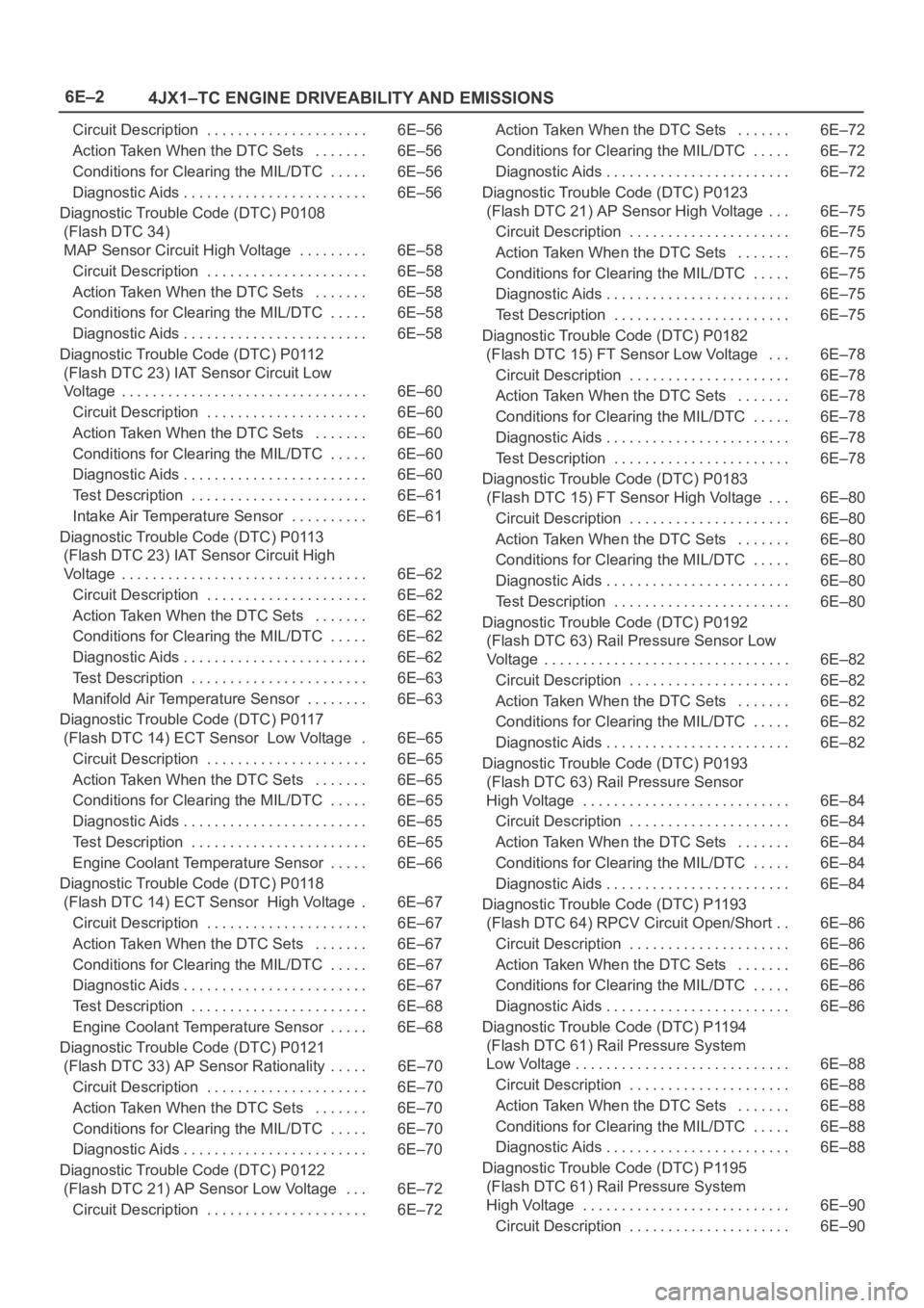
6E–2
4JX1–TC ENGINE DRIVEABILITY AND EMISSIONS
Circuit Description 6E–56. . . . . . . . . . . . . . . . . . . . .
Action Taken When the DTC Sets 6E–56. . . . . . .
Conditions for Clearing the MIL/DTC 6E–56. . . . .
Diagnostic Aids 6E–56. . . . . . . . . . . . . . . . . . . . . . . .
Diagnostic Trouble Code (DTC) P0108
(Flash DTC 34)
MAP Sensor Circuit High Voltage 6E–58. . . . . . . . .
Circuit Description 6E–58. . . . . . . . . . . . . . . . . . . . .
Action Taken When the DTC Sets 6E–58. . . . . . .
Conditions for Clearing the MIL/DTC 6E–58. . . . .
Diagnostic Aids 6E–58. . . . . . . . . . . . . . . . . . . . . . . .
Diagnostic Trouble Code (DTC) P0112
(Flash DTC 23) IAT Sensor Circuit Low
Voltage 6E–60. . . . . . . . . . . . . . . . . . . . . . . . . . . . . . . .
Circuit Description 6E–60. . . . . . . . . . . . . . . . . . . . .
Action Taken When the DTC Sets 6E–60. . . . . . .
Conditions for Clearing the MIL/DTC 6E–60. . . . .
Diagnostic Aids 6E–60. . . . . . . . . . . . . . . . . . . . . . . .
Test Description 6E–61. . . . . . . . . . . . . . . . . . . . . . .
Intake Air Temperature Sensor 6E–61. . . . . . . . . .
Diagnostic Trouble Code (DTC) P0113
(Flash DTC 23) IAT Sensor Circuit High
Voltage 6E–62. . . . . . . . . . . . . . . . . . . . . . . . . . . . . . . .
Circuit Description 6E–62. . . . . . . . . . . . . . . . . . . . .
Action Taken When the DTC Sets 6E–62. . . . . . .
Conditions for Clearing the MIL/DTC 6E–62. . . . .
Diagnostic Aids 6E–62. . . . . . . . . . . . . . . . . . . . . . . .
Test Description 6E–63. . . . . . . . . . . . . . . . . . . . . . .
Manifold Air Temperature Sensor 6E–63. . . . . . . .
Diagnostic Trouble Code (DTC) P0117
(Flash DTC 14) ECT Sensor Low Voltage 6E–65.
Circuit Description 6E–65. . . . . . . . . . . . . . . . . . . . .
Action Taken When the DTC Sets 6E–65. . . . . . .
Conditions for Clearing the MIL/DTC 6E–65. . . . .
Diagnostic Aids 6E–65. . . . . . . . . . . . . . . . . . . . . . . .
Test Description 6E–65. . . . . . . . . . . . . . . . . . . . . . .
Engine Coolant Temperature Sensor 6E–66. . . . .
Diagnostic Trouble Code (DTC) P0118
(Flash DTC 14) ECT Sensor High Voltage 6E–67.
Circuit Description 6E–67. . . . . . . . . . . . . . . . . . . . .
Action Taken When the DTC Sets 6E–67. . . . . . .
Conditions for Clearing the MIL/DTC 6E–67. . . . .
Diagnostic Aids 6E–67. . . . . . . . . . . . . . . . . . . . . . . .
Test Description 6E–68. . . . . . . . . . . . . . . . . . . . . . .
Engine Coolant Temperature Sensor 6E–68. . . . .
Diagnostic Trouble Code (DTC) P0121
(Flash DTC 33) AP Sensor Rationality 6E–70. . . . .
Circuit Description 6E–70. . . . . . . . . . . . . . . . . . . . .
Action Taken When the DTC Sets 6E–70. . . . . . .
Conditions for Clearing the MIL/DTC 6E–70. . . . .
Diagnostic Aids 6E–70. . . . . . . . . . . . . . . . . . . . . . . .
Diagnostic Trouble Code (DTC) P0122
(Flash DTC 21) AP Sensor Low Voltage 6E–72. . .
Circuit Description 6E–72. . . . . . . . . . . . . . . . . . . . . Action Taken When the DTC Sets 6E–72. . . . . . .
Conditions for Clearing the MIL/DTC 6E–72. . . . .
Diagnostic Aids 6E–72. . . . . . . . . . . . . . . . . . . . . . . .
Diagnostic Trouble Code (DTC) P0123
(Flash DTC 21) AP Sensor High Voltage 6E–75. . .
Circuit Description 6E–75. . . . . . . . . . . . . . . . . . . . .
Action Taken When the DTC Sets 6E–75. . . . . . .
Conditions for Clearing the MIL/DTC 6E–75. . . . .
Diagnostic Aids 6E–75. . . . . . . . . . . . . . . . . . . . . . . .
Test Description 6E–75. . . . . . . . . . . . . . . . . . . . . . .
Diagnostic Trouble Code (DTC) P0182
(Flash DTC 15) FT Sensor Low Voltage 6E–78. . .
Circuit Description 6E–78. . . . . . . . . . . . . . . . . . . . .
Action Taken When the DTC Sets 6E–78. . . . . . .
Conditions for Clearing the MIL/DTC 6E–78. . . . .
Diagnostic Aids 6E–78. . . . . . . . . . . . . . . . . . . . . . . .
Test Description 6E–78. . . . . . . . . . . . . . . . . . . . . . .
Diagnostic Trouble Code (DTC) P0183
(Flash DTC 15) FT Sensor High Voltage 6E–80. . .
Circuit Description 6E–80. . . . . . . . . . . . . . . . . . . . .
Action Taken When the DTC Sets 6E–80. . . . . . .
Conditions for Clearing the MIL/DTC 6E–80. . . . .
Diagnostic Aids 6E–80. . . . . . . . . . . . . . . . . . . . . . . .
Test Description 6E–80. . . . . . . . . . . . . . . . . . . . . . .
Diagnostic Trouble Code (DTC) P0192
(Flash DTC 63) Rail Pressure Sensor Low
Voltage 6E–82. . . . . . . . . . . . . . . . . . . . . . . . . . . . . . . .
Circuit Description 6E–82. . . . . . . . . . . . . . . . . . . . .
Action Taken When the DTC Sets 6E–82. . . . . . .
Conditions for Clearing the MIL/DTC 6E–82. . . . .
Diagnostic Aids 6E–82. . . . . . . . . . . . . . . . . . . . . . . .
Diagnostic Trouble Code (DTC) P0193
(Flash DTC 63) Rail Pressure Sensor
High Voltage 6E–84. . . . . . . . . . . . . . . . . . . . . . . . . . .
Circuit Description 6E–84. . . . . . . . . . . . . . . . . . . . .
Action Taken When the DTC Sets 6E–84. . . . . . .
Conditions for Clearing the MIL/DTC 6E–84. . . . .
Diagnostic Aids 6E–84. . . . . . . . . . . . . . . . . . . . . . . .
Diagnostic Trouble Code (DTC) P1193
(Flash DTC 64) RPCV Circuit Open/Short 6E–86. .
Circuit Description 6E–86. . . . . . . . . . . . . . . . . . . . .
Action Taken When the DTC Sets 6E–86. . . . . . .
Conditions for Clearing the MIL/DTC 6E–86. . . . .
Diagnostic Aids 6E–86. . . . . . . . . . . . . . . . . . . . . . . .
Diagnostic Trouble Code (DTC) P1194
(Flash DTC 61) Rail Pressure System
Low Voltage 6E–88. . . . . . . . . . . . . . . . . . . . . . . . . . . .
Circuit Description 6E–88. . . . . . . . . . . . . . . . . . . . .
Action Taken When the DTC Sets 6E–88. . . . . . .
Conditions for Clearing the MIL/DTC 6E–88. . . . .
Diagnostic Aids 6E–88. . . . . . . . . . . . . . . . . . . . . . . .
Diagnostic Trouble Code (DTC) P1195
(Flash DTC 61) Rail Pressure System
High Voltage 6E–90. . . . . . . . . . . . . . . . . . . . . . . . . . .
Circuit Description 6E–90. . . . . . . . . . . . . . . . . . . . .
Page 5434 of 6000
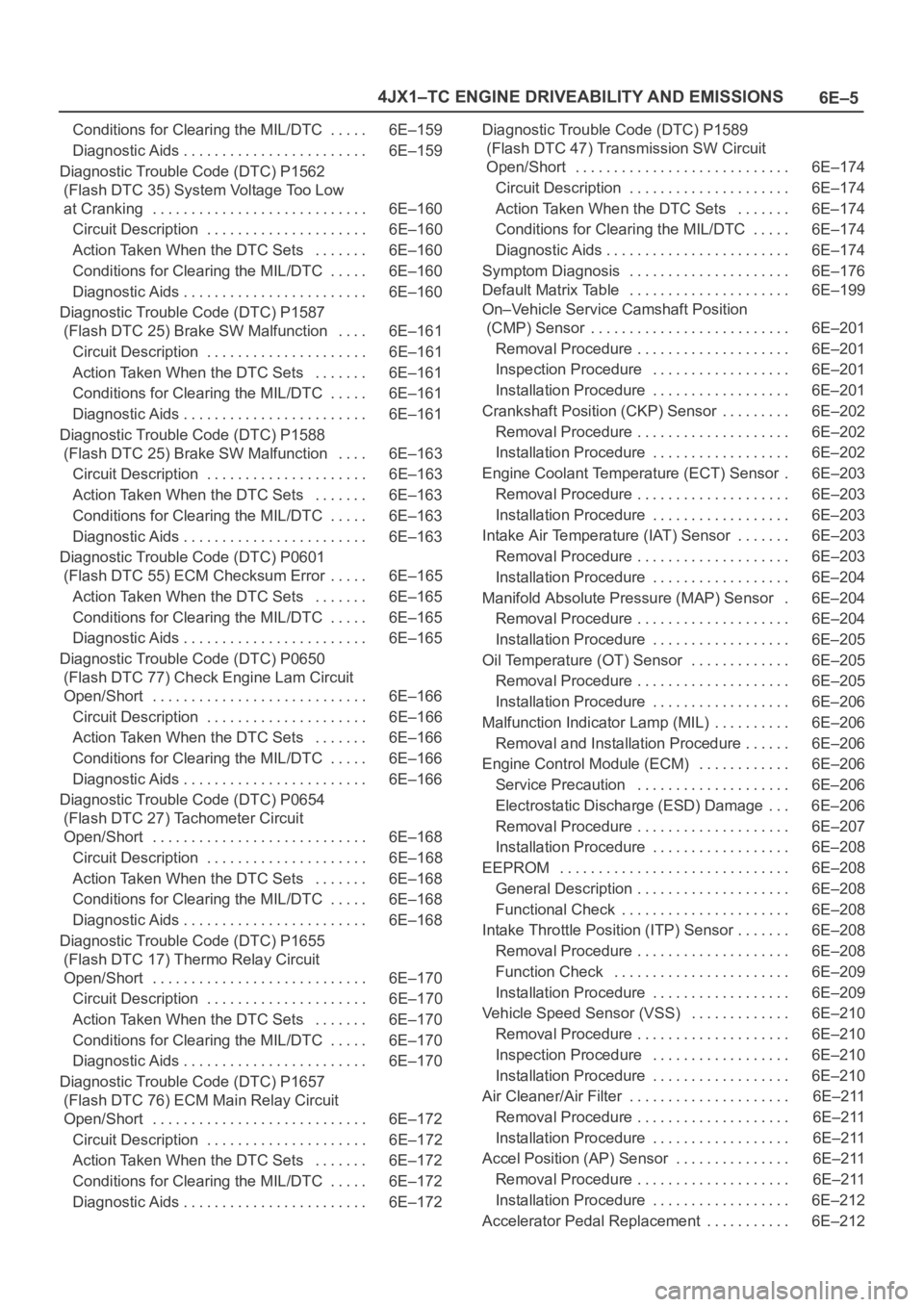
6E–5 4JX1–TC ENGINE DRIVEABILITY AND EMISSIONS
Conditions for Clearing the MIL/DTC 6E–159. . . . .
Diagnostic Aids 6E–159. . . . . . . . . . . . . . . . . . . . . . . .
Diagnostic Trouble Code (DTC) P1562
(Flash DTC 35) System Voltage Too Low
at Cranking 6E–160. . . . . . . . . . . . . . . . . . . . . . . . . . . .
Circuit Description 6E–160. . . . . . . . . . . . . . . . . . . . .
Action Taken When the DTC Sets 6E–160. . . . . . .
Conditions for Clearing the MIL/DTC 6E–160. . . . .
Diagnostic Aids 6E–160. . . . . . . . . . . . . . . . . . . . . . . .
Diagnostic Trouble Code (DTC) P1587
(Flash DTC 25) Brake SW Malfunction 6E–161. . . .
Circuit Description 6E–161. . . . . . . . . . . . . . . . . . . . .
Action Taken When the DTC Sets 6E–161. . . . . . .
Conditions for Clearing the MIL/DTC 6E–161. . . . .
Diagnostic Aids 6E–161. . . . . . . . . . . . . . . . . . . . . . . .
Diagnostic Trouble Code (DTC) P1588
(Flash DTC 25) Brake SW Malfunction 6E–163. . . .
Circuit Description 6E–163. . . . . . . . . . . . . . . . . . . . .
Action Taken When the DTC Sets 6E–163. . . . . . .
Conditions for Clearing the MIL/DTC 6E–163. . . . .
Diagnostic Aids 6E–163. . . . . . . . . . . . . . . . . . . . . . . .
Diagnostic Trouble Code (DTC) P0601
(Flash DTC 55) ECM Checksum Error 6E–165. . . . .
Action Taken When the DTC Sets 6E–165. . . . . . .
Conditions for Clearing the MIL/DTC 6E–165. . . . .
Diagnostic Aids 6E–165. . . . . . . . . . . . . . . . . . . . . . . .
Diagnostic Trouble Code (DTC) P0650
(Flash DTC 77) Check Engine Lam Circuit
Open/Short 6E–166. . . . . . . . . . . . . . . . . . . . . . . . . . . .
Circuit Description 6E–166. . . . . . . . . . . . . . . . . . . . .
Action Taken When the DTC Sets 6E–166. . . . . . .
Conditions for Clearing the MIL/DTC 6E–166. . . . .
Diagnostic Aids 6E–166. . . . . . . . . . . . . . . . . . . . . . . .
Diagnostic Trouble Code (DTC) P0654
(Flash DTC 27) Tachometer Circuit
Open/Short 6E–168. . . . . . . . . . . . . . . . . . . . . . . . . . . .
Circuit Description 6E–168. . . . . . . . . . . . . . . . . . . . .
Action Taken When the DTC Sets 6E–168. . . . . . .
Conditions for Clearing the MIL/DTC 6E–168. . . . .
Diagnostic Aids 6E–168. . . . . . . . . . . . . . . . . . . . . . . .
Diagnostic Trouble Code (DTC) P1655
(Flash DTC 17) Thermo Relay Circuit
Open/Short 6E–170. . . . . . . . . . . . . . . . . . . . . . . . . . . .
Circuit Description 6E–170. . . . . . . . . . . . . . . . . . . . .
Action Taken When the DTC Sets 6E–170. . . . . . .
Conditions for Clearing the MIL/DTC 6E–170. . . . .
Diagnostic Aids 6E–170. . . . . . . . . . . . . . . . . . . . . . . .
Diagnostic Trouble Code (DTC) P1657
(Flash DTC 76) ECM Main Relay Circuit
Open/Short 6E–172. . . . . . . . . . . . . . . . . . . . . . . . . . . .
Circuit Description 6E–172. . . . . . . . . . . . . . . . . . . . .
Action Taken When the DTC Sets 6E–172. . . . . . .
Conditions for Clearing the MIL/DTC 6E–172. . . . .
Diagnostic Aids 6E–172. . . . . . . . . . . . . . . . . . . . . . . . Diagnostic Trouble Code (DTC) P1589
(Flash DTC 47) Transmission SW Circuit
Open/Short 6E–174. . . . . . . . . . . . . . . . . . . . . . . . . . . .
Circuit Description 6E–174. . . . . . . . . . . . . . . . . . . . .
Action Taken When the DTC Sets 6E–174. . . . . . .
Conditions for Clearing the MIL/DTC 6E–174. . . . .
Diagnostic Aids 6E–174. . . . . . . . . . . . . . . . . . . . . . . .
Symptom Diagnosis 6E–176. . . . . . . . . . . . . . . . . . . . .
Default Matrix Table 6E–199. . . . . . . . . . . . . . . . . . . . .
On–Vehicle Service Camshaft Position
(CMP) Sensor 6E–201. . . . . . . . . . . . . . . . . . . . . . . . . .
Removal Procedure 6E–201. . . . . . . . . . . . . . . . . . . .
Inspection Procedure 6E–201. . . . . . . . . . . . . . . . . .
Installation Procedure 6E–201. . . . . . . . . . . . . . . . . .
Crankshaft Position (CKP) Sensor 6E–202. . . . . . . . .
Removal Procedure 6E–202. . . . . . . . . . . . . . . . . . . .
Installation Procedure 6E–202. . . . . . . . . . . . . . . . . .
Engine Coolant Temperature (ECT) Sensor 6E–203.
Removal Procedure 6E–203. . . . . . . . . . . . . . . . . . . .
Installation Procedure 6E–203. . . . . . . . . . . . . . . . . .
Intake Air Temperature (IAT) Sensor 6E–203. . . . . . .
Removal Procedure 6E–203. . . . . . . . . . . . . . . . . . . .
Installation Procedure 6E–204. . . . . . . . . . . . . . . . . .
Manifold Absolute Pressure (MAP) Sensor 6E–204.
Removal Procedure 6E–204. . . . . . . . . . . . . . . . . . . .
Installation Procedure 6E–205. . . . . . . . . . . . . . . . . .
Oil Temperature (OT) Sensor 6E–205. . . . . . . . . . . . .
Removal Procedure 6E–205. . . . . . . . . . . . . . . . . . . .
Installation Procedure 6E–206. . . . . . . . . . . . . . . . . .
Malfunction Indicator Lamp (MIL) 6E–206. . . . . . . . . .
Removal and Installation Procedure 6E–206. . . . . .
Engine Control Module (ECM) 6E–206. . . . . . . . . . . .
Service Precaution 6E–206. . . . . . . . . . . . . . . . . . . .
Electrostatic Discharge (ESD) Damage 6E–206. . .
Removal Procedure 6E–207. . . . . . . . . . . . . . . . . . . .
Installation Procedure 6E–208. . . . . . . . . . . . . . . . . .
EEPROM 6E–208. . . . . . . . . . . . . . . . . . . . . . . . . . . . . .
General Description 6E–208. . . . . . . . . . . . . . . . . . . .
Functional Check 6E–208. . . . . . . . . . . . . . . . . . . . . .
Intake Throttle Position (ITP) Sensor 6E–208. . . . . . .
Removal Procedure 6E–208. . . . . . . . . . . . . . . . . . . .
Function Check 6E–209. . . . . . . . . . . . . . . . . . . . . . .
Installation Procedure 6E–209. . . . . . . . . . . . . . . . . .
Vehicle Speed Sensor (VSS) 6E–210. . . . . . . . . . . . .
Removal Procedure 6E–210. . . . . . . . . . . . . . . . . . . .
Inspection Procedure 6E–210. . . . . . . . . . . . . . . . . .
Installation Procedure 6E–210. . . . . . . . . . . . . . . . . .
Air Cleaner/Air Filter 6E–211. . . . . . . . . . . . . . . . . . . . .
Removal Procedure 6E–211. . . . . . . . . . . . . . . . . . . .
Installation Procedure 6E–211. . . . . . . . . . . . . . . . . .
Accel Position (AP) Sensor 6E–211. . . . . . . . . . . . . . .
Removal Procedure 6E–211. . . . . . . . . . . . . . . . . . . .
Installation Procedure 6E–212. . . . . . . . . . . . . . . . . .
Accelerator Pedal Replacement 6E–212. . . . . . . . . . .