1998 OPEL FRONTERA Back
[x] Cancel search: BackPage 5823 of 6000
7A–42 AUTOMATIC TRANSMISSION (AW30-40LE)
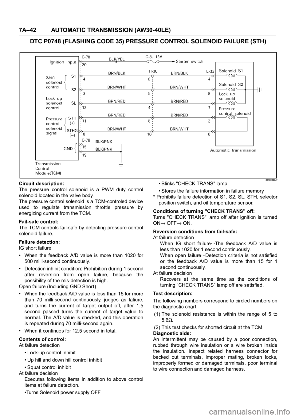
DTC P0748 (FLASHING CODE 35) PRESSURE CONTROL SOLENOID FAILURE (STH)
D07RY00047Circuit description:
The pressure control solenoid is a PWM duty control
solenoid located in the valve body.
The pressure control solenoid is a TCM-controled device
used to regulate transmission throttle pressure by
energizing current from the TCM.
Fail-safe control:
The TCM controls fail-safe by detecting pressure control
solenoid failure.
Failure detection:
IG shor t failure
• When the feedback A/D value is more than 1020 for
500 milli-second continuously.
• Detection inhibit condition: Prohibition during 1 second
after reversion from open failure, because the
possibility of the mis-detection is high.
Open failure (Including GND Shor t)
• When the feedback A/D value is less than 15 for more
than 70 milli-second continuously, judges as faliure,
and turns the current of target output off, after 1.5
second passed turns the current of target value to
normal. The A/D value is checked, and this operation
is repeated during 70 milli-second again.
• When it continues for 12.5 second in total.
Contents of control:
At failure detection
• Lock-up control inhibit
• Up hill and down hill control inhibit
• Squat control inhibit
At failure decision
Executes following items in addition to above control
items at failure detection.
•Turns Solenoid power supply OFF• Blinks "CHECK TRANS" lamp
• Stores the failure information in failure memory
* Prohibits failure detection of S1, S2, SL, STH, selector
position switch, and oil temperature sensor.
Conditions of turning "CHECK TRANS" off:
Turns "CHECK TRANS" lamp off after ignition is turned
ON
OFF ON.
Reversion conditions from fail-safe:
At failure detection
W h e n I G sh o r t fa i l u re ꞏꞏꞏT h e fe e d ba ck A / D va l u e i s
less than 1020 for 1 second continuously.
W h e n o p e n fa i l u re ꞏꞏꞏD e t e c t i o n c r i t e r i a i s n o t s a t i s f i e d
or the feedback A/D value is more than 15 for 1
second continuously.
At failure decision
Recovers at the same time as the conditions of
turning “CHECK TRANS” lamp off are satisfied.
Test description:
The following numbers correspond to circled numbers on
the diagnostic char t.
(1) The solenoid resistance is within the range of 5 to
5.6
.
(2) This test checks for shor ted circuit at the TCM.
Diagnostic aids:
An intermittent may be caused by a poor connection,
rubbed through wire insulation or a wire broken inside
the insulation. Inspect related harness connector for
backed out terminals, improper mating, broken locks,
improperly formed or damaged terminals, poor terminal
to wire connection and damaged harness.
Page 5825 of 6000
7A–44 AUTOMATIC TRANSMISSION (AW30-40LE)
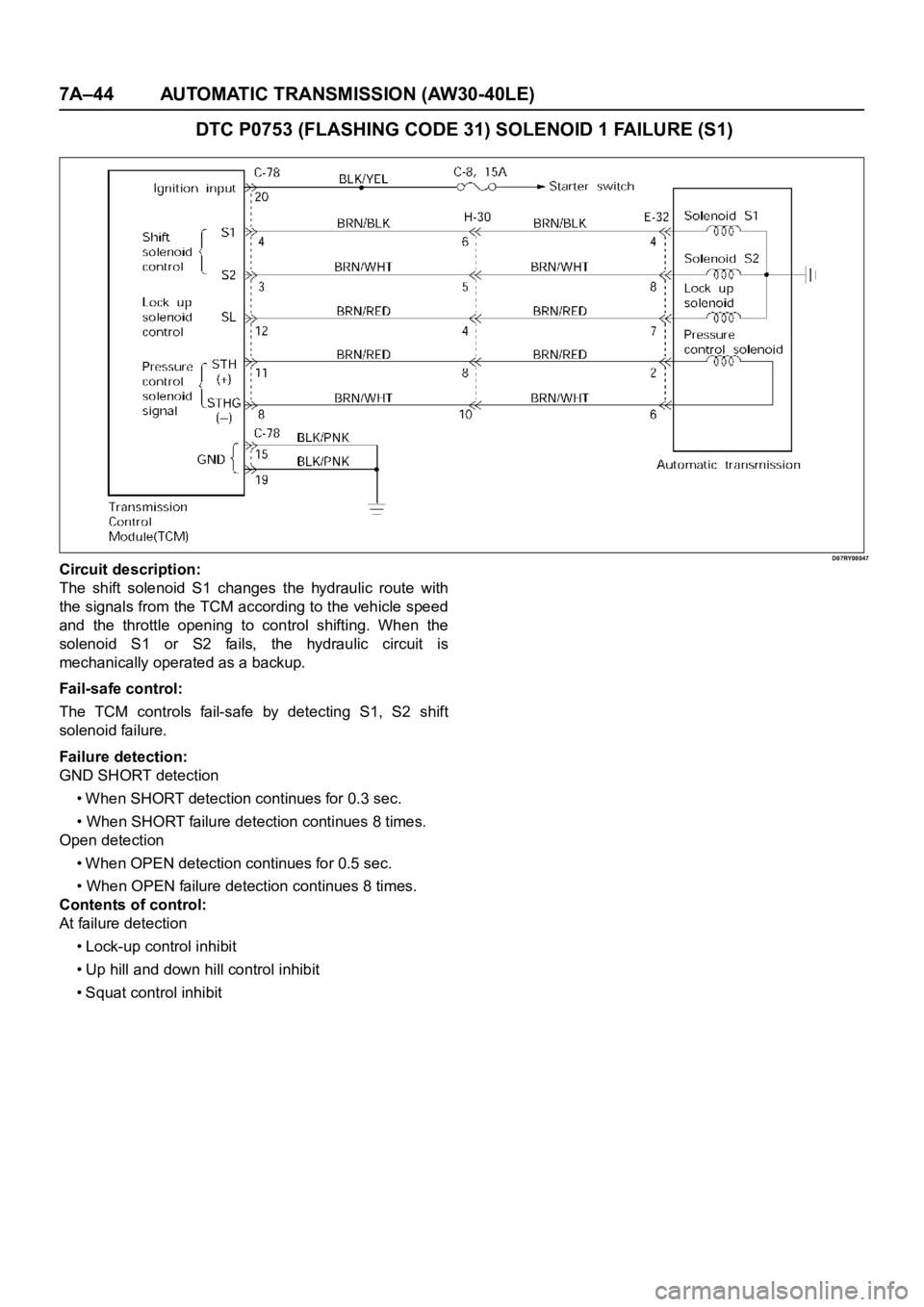
DTC P0753 (FLASHING CODE 31) SOLENOID 1 FAILURE (S1)
D07RY00047Circuit description:
The shift solenoid S1 changes the hydraulic route with
the signals from the TCM according to the vehicle speed
and the throttle opening to control shifting. When the
solenoid S1 or S2 fails, the hydraulic circuit is
mechanically operated as a backup.
Fail-safe control:
The TCM controls fail-safe by detecting S1, S2 shift
solenoid failure.
Failure detection:
GND SHORT detection
• When SHORT detection continues for 0.3 sec.
• When SHORT failure detection continues 8 times.
Open detection
• When OPEN detection continues for 0.5 sec.
• When OPEN failure detection continues 8 times.
Contents of control:
At failure detection
• Lock-up control inhibit
• Up hill and down hill control inhibit
• Squat control inhibit
Page 5829 of 6000
7A–48 AUTOMATIC TRANSMISSION (AW30-40LE)
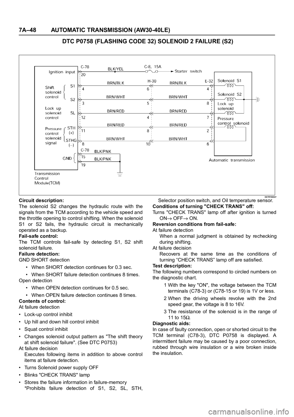
DTC P0758 (FLASHING CODE 32) SOLENOID 2 FAILURE (S2)
D07RY00047Circuit description:
The solenoid S2 changes the hydraulic route with the
signals from the TCM according to the vehicle speed and
the throttle opening to control shifting. When the solenoid
S1 or S2 fails, the hydraulic circuit is mechanically
operated as a backup.
Fail-safe control:
The TCM controls fail-safe by detecting S1, S2 shift
solenoid failure.
Failure detection:
GND SHORT detection
• When SHORT detection continues for 0.3 sec.
• When SHORT failure detection continues 8 times.
Open detection
• When OPEN detection continues for 0.5 sec.
• When OPEN failure detection continues 8 times.
Contents of control:
At failure detection
• Lock-up control inhibit
• Up hill and down hill control inhibit
• Squat control inhibit
• Changes solenoid output pattern as "The shift theory
at shift solenoid failure". (See DTC P0753)
At failure decision
Executes following items in addition to above control
items at failure detection.
• Turns Solenoid power supply OFF
• Blinks "CHECK TRANS" lamp
• Stores the failure information in failure-memory
*Prohibits failure detection of S1, S2, SL, STH,Selector position switch, and Oil temperature sensor.
Conditions of turning "CHECK TRANS" off:
Turns "CHECK TRANS" lamp off after ignition is turned
ON
OFF ON.
Reversion conditions from fail-safe:
At failure detection
When a normal judgment is obtained by rechecking
during shifting.
At failure decision
Recovers at the same time as the conditions of
turning “CHECK TRANS” lamp off are satisfied.
Test description:
The following numbers correspond to circled numbers on
the diagnostic char t.
1 With the key "ON", the voltage between the TCM
terminals (C78-3) or (C78-15 or 19) is 1V or less.
2 When the driving wheels revolve with the 2nd
speed gear, the voltage is 8 to 16V.
3 The resistance of the solenoid is in the range of
11 to 15
.
Diagnostic aids:
In case of faulty connection, open or shor ted circuit to the
TCM terminal (C78-3), DTC P0758 is displayed. A
intermittent failure may be caused by a poor connection,
rubbed through wire insulation or a wire broken inside
the insulation.
Page 5831 of 6000
7A–50 AUTOMATIC TRANSMISSION (AW30-40LE)
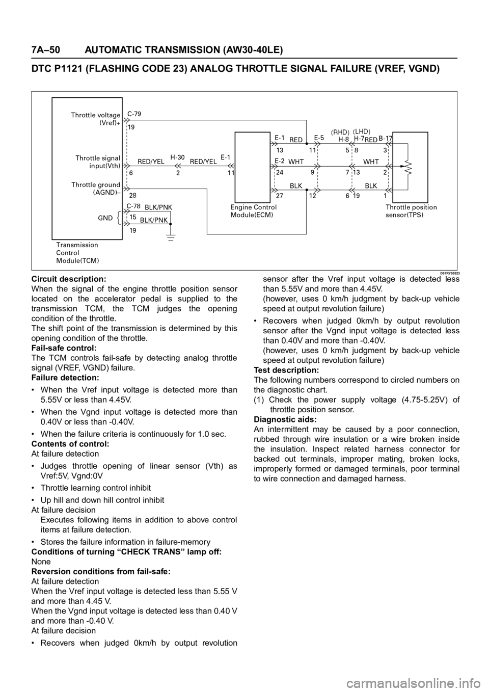
DTC P1121 (FLASHING CODE 23) ANALOG THROTTLE SIGNAL FAILURE (VREF, VGND)
D07RY00023Circuit description:
When the signal of the engine throttle position sensor
located on the accelerator pedal is supplied to the
transmission TCM, the TCM judges the opening
condition of the throttle.
The shift point of the transmission is determined by this
opening condition of the throttle.
Fail-safe control:
The TCM controls fail-safe by detecting analog throttle
signal (VREF, VGND) failure.
Failure detection:
• When the Vref input voltage is detected more than
5.55V or less than 4.45V.
• When the Vgnd input voltage is detected more than
0.40V or less than -0.40V.
• When the failure criteria is continuously for 1.0 sec.
Contents of control:
At failure detection
• Judges throttle opening of linear sensor (Vth) as
Vref:5V, Vgnd:0V
• Throttle learning control inhibit
• Up hill and down hill control inhibit
At failure decision
Executes following items in addition to above control
items at failure detection.
• Stores the failure information in failure-memory
Conditions of turning “CHECK TRANS” lamp off:
None
Reversion conditions from fail-safe:
At failure detection
When the Vref input voltage is detected less than 5.55 V
and more than 4.45 V.
When the Vgnd input voltage is detected less than 0.40 V
and more than -0.40 V.
At failure decision
• Recovers when judged 0km/h by output revolutionsensor after the Vref input voltage is detected less
than 5.55V and more than 4.45V.
(however, uses 0 km/h judgment by back-up vehicle
speed at output revolution failure)
• Recovers when judged 0km/h by output revolution
sensor after the Vgnd input voltage is detected less
than 0.40V and more than -0.40V.
(however, uses 0 km/h judgment by back-up vehicle
speed at output revolution failure)
Test description:
The following numbers correspond to circled numbers on
the diagnostic char t.
(1) Check the power supply voltage (4.75-5.25V) of
throttle position sensor.
Diagnostic aids:
An intermittent may be caused by a poor connection,
rubbed through wire insulation or a wire broken inside
the insulation. Inspect related harness connector for
backed out terminals, improper mating, broken locks,
improperly formed or damaged terminals, poor terminal
to wire connection and damaged harness.
Page 5852 of 6000
AUTOMATIC TRANSMISSION (AW30-40LE) 7A–71
826RY00017
TCM VOLTAGE CHECK
TCM voltage check is done to check for transmission and
transmission control module (TCM) problems which cannot be
detected by self-diagnosis.
Additionally, it serves as a back-up check for self-diagnosis.
Measure the voltage drop and make a continuity test for each
of the sensors, solenoids, and switches.
If the voltage is within the specified range and continuity exists,
that particular area of the TCM and automatic transmission
assembly is normal.
If voltage deviation or lack of continuity is discovered,
disconnect the applicable parts and check each of them
individually.
This will allow you to determine the trouble location (TCM,
automatic transmission unit, or another area of the vehicle).
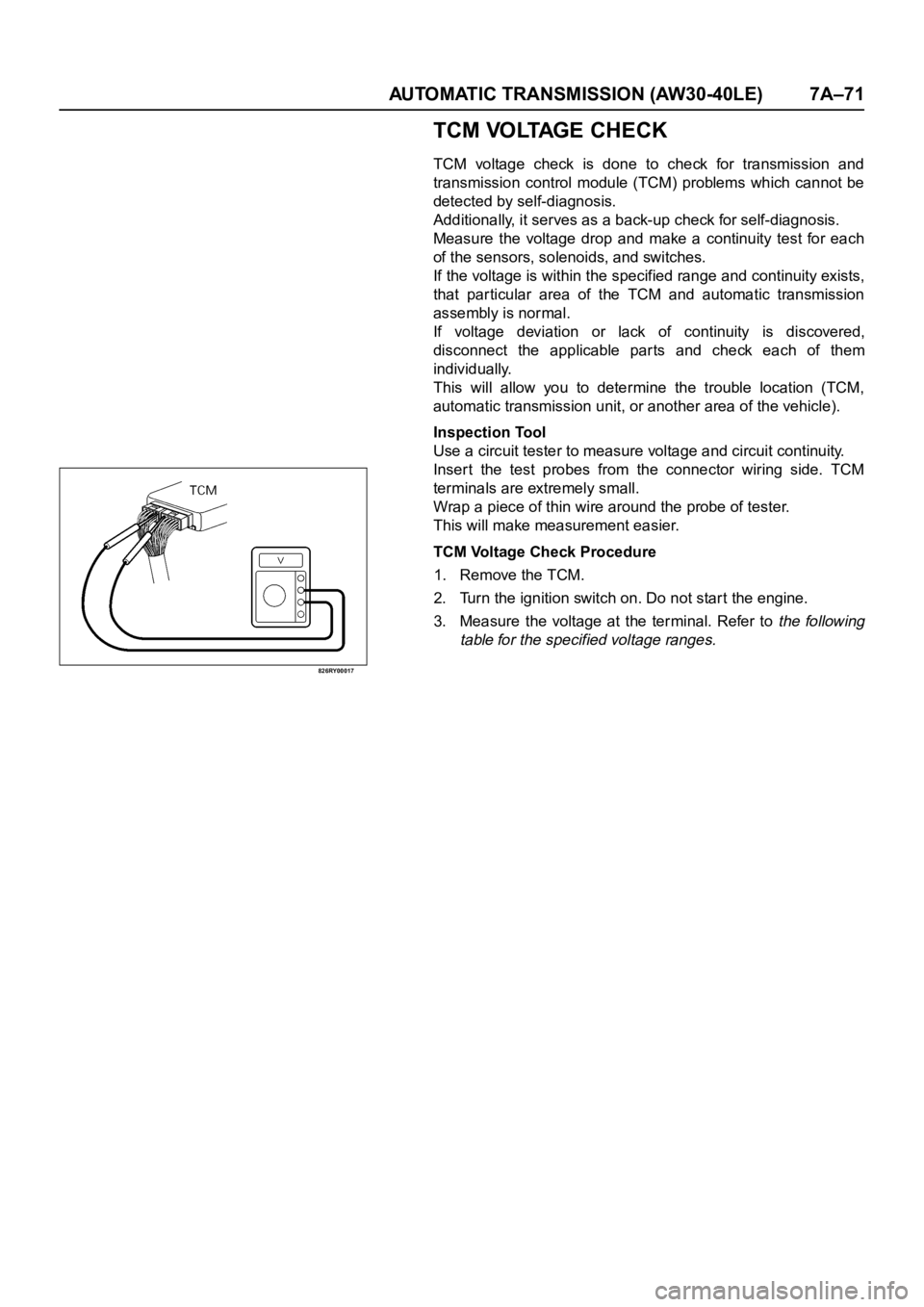
Inspection Tool
Use a circuit tester to measure voltage and circuit continuity.
Inser t the test probes from the connector wiring side. TCM
terminals are extremely small.
Wrap a piece of thin wire around the probe of tester.
This will make measurement easier.
TCM Voltage Check Procedure
1. Remove the TCM.
2. Turn the ignition switch on. Do not start the engine.
3. Measure the voltage at the terminal. Refer to
the following
table for the specified voltage ranges.
Page 5987 of 6000
7A–206 AUTOMATIC TRANSMISSION (AW30-40LE)
249RW003
249RY00008
240RY00005
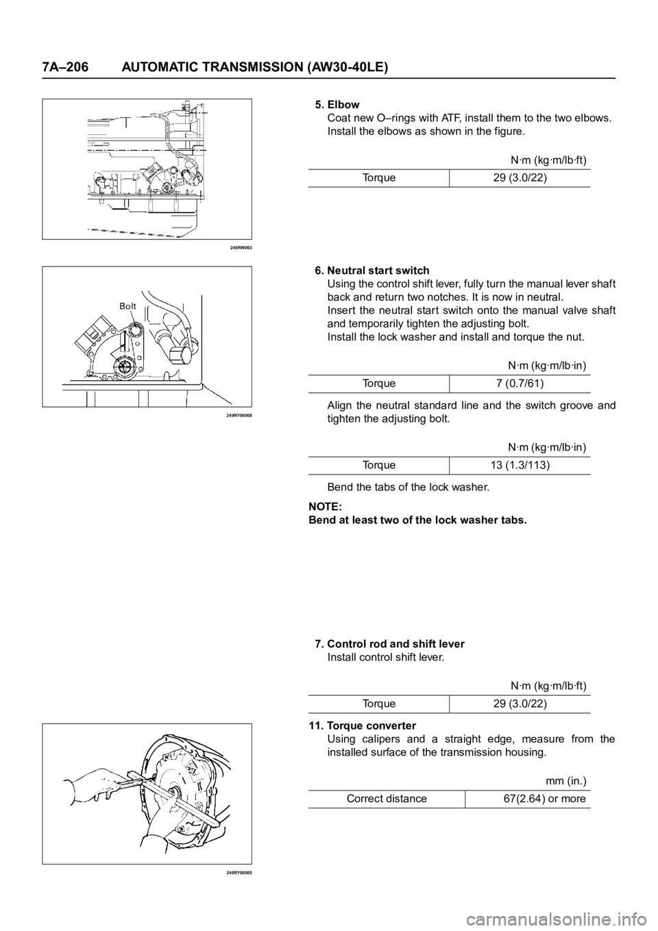
5. Elbow
Coat new O–rings with ATF, install them to the two elbows.
Install the elbows as shown in the figure.
6. Neutral start switch
Using the control shift lever, fully turn the manual lever shaft
back and return two notches. It is now in neutral.
Insert the neutral star t switch onto the manual valve shaft
and temporarily tighten the adjusting bolt.
Install the lock washer and install and torque the nut.
Align the neutral standard line and the switch groove and
tighten the adjusting bolt.
Bend the tabs of the lock washer.
NOTE:
Bend at least two of the lock washer tabs.
7. Control rod and shift lever
Install control shift lever.
11. Torque converter
Using calipers and a straight edge, measure from the
installed surface of the transmission housing.Nꞏm (kgꞏm/lbꞏft)
Torque 29 (3.0/22)
Nꞏm (kgꞏm/lbꞏin)
To r q u e 7 ( 0 . 7 / 6 1 )
Nꞏm (kgꞏm/lbꞏin)
Torque 13 (1.3/113)
Nꞏm (kgꞏm/lbꞏft)
Torque 29 (3.0/22)
mm (in.)
Correct distance 67(2.64) or more
Page 5994 of 6000
TRANSMISSION CONTROL SYSTEM (4L30–E)7A1–1
TRANSMISSION
TRANSMISSION CONTROL SYSTEM (4L30–E)
CONTENTS
Service Precaution 7A1–2. . . . . . . . . . . . . . . . . . . . . .
General Description 7A1–2. . . . . . . . . . . . . . . . . . . . .
Electronic Control Diagram 7A1–3. . . . . . . . . . . . .
Powertrain Control Module (PCM) 7A1–4. . . . . . .
Control System Diagram 7A1–5. . . . . . . . . . . . . . .
Shift Control 7A1–6. . . . . . . . . . . . . . . . . . . . . . . . . .
Band Apply Control 7A1–6. . . . . . . . . . . . . . . . . . . .
Torque Converter Clutch Control 7A1–6. . . . . . . . .
Line Pressure Control 7A1–6. . . . . . . . . . . . . . . . . .
On–Board Diagnostic System 7A1–6. . . . . . . . . . .
Fail Safe Mechanism 7A1–6. . . . . . . . . . . . . . . . . . .
Torque Management Control 7A1–6. . . . . . . . . . . .
ATF Warning Control 7A1–6. . . . . . . . . . . . . . . . . . .
ABS Control (If equipped) 7A1–6. . . . . . . . . . . . . .
Shift Mode Control 7A1–7. . . . . . . . . . . . . . . . . . . . .
Gear Shift Control 7A1–8. . . . . . . . . . . . . . . . . . . . .
Winter Drive Mode 7A1–9. . . . . . . . . . . . . . . . . . . . .
Backup Mode 7A1–9. . . . . . . . . . . . . . . . . . . . . . . . .
Functions of Input / Output Components 7A1–10. .
Diagnosis 7A1–11. . . . . . . . . . . . . . . . . . . . . . . . . . . . . .
Electronic Diagnosis 7A1–11. . . . . . . . . . . . . . . . . . .
Check Trans Indicator 7A1–11. . . . . . . . . . . . . . . . . .
Diagnostic Check 7A1–11. . . . . . . . . . . . . . . . . . . . . .
“Check Trans” Check 7A1–12. . . . . . . . . . . . . . . . . .
Tech2 OBD II Connection 7A1–13. . . . . . . . . . . . . . .
F0: Transmission Data 7A1–18. . . . . . . . . . . . . . . . .
F1: PC Solenoid Data 7A1–19. . . . . . . . . . . . . . . . . .
OBD II Diagnostic Management System 7A1–20. .
16 – Terminal Data Link Connector (DLC) 7A1–21.
Malfunction Indicator Lamp (MIL) 7A1–22. . . . . . . .
Types Of Diagnostic Trouble Codes (DTCs) 7A1–22
Clear DTC 7A1–22. . . . . . . . . . . . . . . . . . . . . . . . . . . .
DTC Check 7A1–23. . . . . . . . . . . . . . . . . . . . . . . . . . .
PCM Precaution 7A1–23. . . . . . . . . . . . . . . . . . . . . . .
Information On PCM 7A1–23. . . . . . . . . . . . . . . . . . .
Intermittent Conditions 7A1–23. . . . . . . . . . . . . . . . . Transmission And PCM Identification 7A1–24. . . . .
Isuzu Trooper 7A1–25. . . . . . . . . . . . . . . . . . . . . . . . .
Diagnostic Trouble Code (DTC)
Identification 7A1–26. . . . . . . . . . . . . . . . . . . . . . . . .
DTC P0218 Transmission Fluid Over
Temperature 7A1–27. . . . . . . . . . . . . . . . . . . . . . . . . . .
DTC P0560 System Voltage Malfunction 7A1–29. . .
DTC P0705 Transmission Range Switch
(Mode Switch) Illegal Position 7A1–32. . . . . . . . . . . .
DTC P0706 Transmission Range Switch
(Mode Switch) Performance 7A1–35. . . . . . . . . . . . . .
DTC P0712 Transmission Fluid Temperature
(TFT) Sensor Circuit Low Input 7A1–38. . . . . . . . . . .
DTC P0713 Transmission Fluid Temperature
(TFT) Sensor Circuit High Input 7A1–41. . . . . . . . . . .
DTC P0719 TCC Brake Switch Circuit High
(Stuck On) 7A1–44. . . . . . . . . . . . . . . . . . . . . . . . . . . . .
DTC P0722 Transmission Output Speed
Sensor (OSS) Low Input 7A1–47
. . . . . . . . . . . . . . . . .
DTC P0723 Transmission Output Speed
Sensor (OSS) Intermittent 7A1–50. . . . . . . . . . . . . . .
DTC P0730 Transmission Incorrect Gear
Ratio 7A1–53. . . . . . . . . . . . . . . . . . . . . . . . . . . . . . . . . .
DTC P0748 Pressure Control Solenoid
(PCS) (Force Motor) Circuit Electrical 7A1–56. . . . .
DTC P0753 Shift Solenoid A Electrical 7A1–58. . . . .
DTC P0758 Shift Solenoid B Electrical 7A1–61. . . . .
DTC P1790 ROM Transmission Side Bad
Check Sum 7A1–65. . . . . . . . . . . . . . . . . . . . . . . . . . . .
DTC P1792 EEPROM Transmission Side
Bad Check Sum 7A1–66. . . . . . . . . . . . . . . . . . . . . . . .
DTC P1835 Kickdown Switch Always On 7A1–67. . .
DTC P1850 Brake Band Apply Solenoid
Malfunction 7A1–69. . . . . . . . . . . . . . . . . . . . . . . . . . . .
DTC P1860 TCC Solenoid Electrical 7A1–73. . . . . . .
Transmission Fluid Temperature (TFT)
Sensor Specifications 7A1–76. . . . . . . . . . . . . . . . . . .
Page 5995 of 6000
7A1–2
TRANSMISSION CONTROL SYSTEM (4L30–E)
Service Precaution
WARNING: IF SO EQUIPPED WITH A
SUPPLEMENTAL RESTRAINT SYSTEM (SRS),
REFER TO THE SRS COMPONENT AND WIRING
LOCATION VIEW IN ORDER TO DETERMINE
WHETHER YOU ARE PERFORMING SERVICE ON OR
NEAR THE SRS COMPONENTS OR THE SRS
WIRING. WHEN YOU ARE PERFORMING SERVICE
ON OR NEAR THE SRS COMPONENTS OR THE SRS
WIRING, REFER TO THE SRS SERVICE
INFORMATION. FAILURE TO FOLLOW WARNINGS
COULD RESULT IN POSSIBLE AIR BAG
DEPLOYMENT, PERSONAL INJURY, OR
OTHERWISE UNNEEDED SRS SYSTEM REPAIRS.
CAUTION: Always use the correct fastener in the
proper location. When you replace a fastener, use
ONLY the exact part number for that application.
ISUZU will call out those fasteners that require a
replacement after removal. ISUZU will also call out
the fasteners that require thread lockers or thread
sealant. UNLESS OTHERWISE SPECIFIED, do not
use supplemental coatings (Paints, greases, or other
corrosion inhibitors) on threaded fasteners or
fastener joint interfaces. Generally, such coatings
adversely affect the fastener torque and the joint
clamping force, and may damage the fastener. When
you install fasteners, use the correct tightening
sequence and specifications. Following these
instructions can help you avoid damage to parts and
systems.
General Description
The 4L30–E is a 4–speed fully automatic transmission. It
uses a microcomputer as a control unit to judge running
conditions including throttle opening rate and vehicle
speed, then it sets the shifting point in the optimum timing
so that best driving performance can be achieved.
In addition, the built–in shift mode select function can
select three shift modes according to the driver’s
preference:
Normal mode –Normal shift pattern.
Winter mode –Starts in 3rd gear to reduce slippage on
ice or snow.
Power mode has a delayed upshift for when more
powerful acceleration is required.
Also, the built–in fail safe function (“backup mode”)
assures driving performance even if the vehicle speed
sensor, throttle signal or any solenoid fails.
Further, the self–diagnostic function conducts diagnosis
in a short time when the control system fails, thus
improving serviceability.
The major features of 4L30–E are as follows:
A compact structure consisting of 2 sets of planetary
gears and flat torque converter.
Electronic control selects the optimum shift mode
according to the driving conditions.
Electronic control maintains the optimum hydraulic
pressure for clutch, band brake as well as
transmission so that shift feeling is improved.
Two sets of planetary gears reduce friction of power
train.
Also, a lockup mechanism in the torque converter
reduces fuel consumption.
Wide gear ratio and high torque rate of torque
converter provide excellent starting performance.