Page 5736 of 6000
7A–47 AUTOMATIC TRANSMISSION (4L30–E)
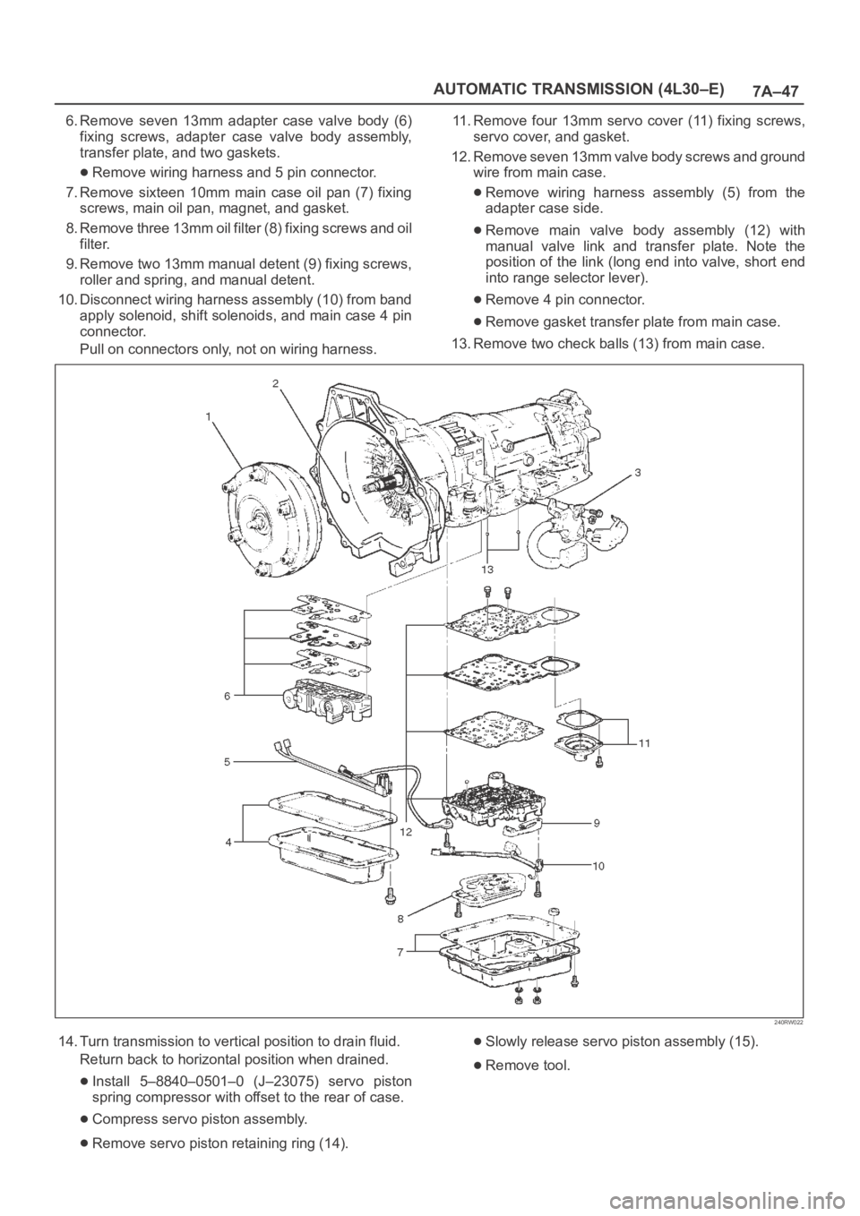
6. Remove seven 13mm adapter case valve body (6)
fixing screws, adapter case valve body assembly,
transfer plate, and two gaskets.
Remove wiring harness and 5 pin connector.
7. Remove sixteen 10mm main case oil pan (7) fixing
screws, main oil pan, magnet, and gasket.
8. Remove three 13mm oil filter (8) fixing screws and oil
filter.
9. Remove two 13mm manual detent (9) fixing screws,
roller and spring, and manual detent.
10. Disconnect wiring harness assembly (10) from band
apply solenoid, shift solenoids, and main case 4 pin
connector.
Pull on connectors only, not on wiring harness.11. Remove four 13mm servo cover (11) fixing screws,
servo cover, and gasket.
12. Remove seven 13mm valve body screws and ground
wire from main case.
Remove wiring harness assembly (5) from the
adapter case side.
Remove main valve body assembly (12) with
manual valve link and transfer plate. Note the
position of the link (long end into valve, short end
into range selector lever).
Remove 4 pin connector.
Remove gasket transfer plate from main case.
13. Remove two check balls (13) from main case.
240RW022
14. Turn transmission to vertical position to drain fluid.
Return back to horizontal position when drained.
Install 5–8840–0501–0 (J–23075) servo piston
spring compressor with offset to the rear of case.
Compress servo piston assembly.
Remove servo piston retaining ring (14).
Slowly release servo piston assembly (15).
Remove tool.
Page 5746 of 6000
7A–57 AUTOMATIC TRANSMISSION (4L30–E)
241RW009
241RW019
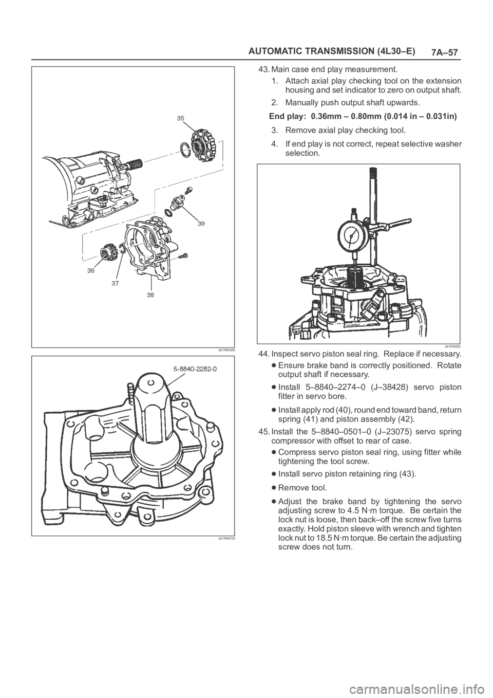
43. Main case end play measurement.
1. Attach axial play checking tool on the extension
housing and set indicator to zero on output shaft.
2. Manually push output shaft upwards.
End play: 0.36mm – 0.80mm (0.014 in – 0.031in)
3. Remove axial play checking tool.
4. If end play is not correct, repeat selective washer
selection.
241RS005
44. Inspect servo piston seal ring. Replace if necessary.
Ensure brake band is correctly positioned. Rotate
output shaft if necessary.
Install 5–8840–2274–0 (J–38428) servo piston
fitter in servo bore.
Install apply rod (40), round end toward band, return
spring (41) and piston assembly (42).
45. Install the 5–8840–0501–0 (J–23075) servo spring
compressor with offset to rear of case.
Compress servo piston seal ring, using fitter while
tightening the tool screw.
Install servo piston retaining ring (43).
Remove tool.
Adjust the brake band by tightening the servo
adjusting screw to 4.5 Nꞏm torque. Be certain the
lock nut is loose, then back–off the screw five turns
exactly. Hold piston sleeve with wrench and tighten
lock nut to 18.5 Nꞏm torque. Be certain the adjusting
screw does not turn.
Page 5765 of 6000
7A–76
AUTOMATIC TRANSMISSION (4L30–E)
Overrun Clutch And Turbine Shaft
Disassembled View
252RW005
Legend
(1) Snap Ring
(2) Overdrive Carrier Assembly
(3) Sun Gear
(4) Turbine Shaft
(5) Snap Ring
(6) Backing Plate
(7) Clutch Plates(8) Snap Ring
(9) Overrun Roller Clutch Cam
(10) Roller Clutch Assembly
(11) Overrun Clutch Release Spring Retainer
(12) Diaphragm Spring
(13) Piston Assembly
(14) Overrun Clutch Drum
(15) Turbine Shaft Seal Rings
Page 5766 of 6000
7A–77 AUTOMATIC TRANSMISSION (4L30–E)
Disassembly
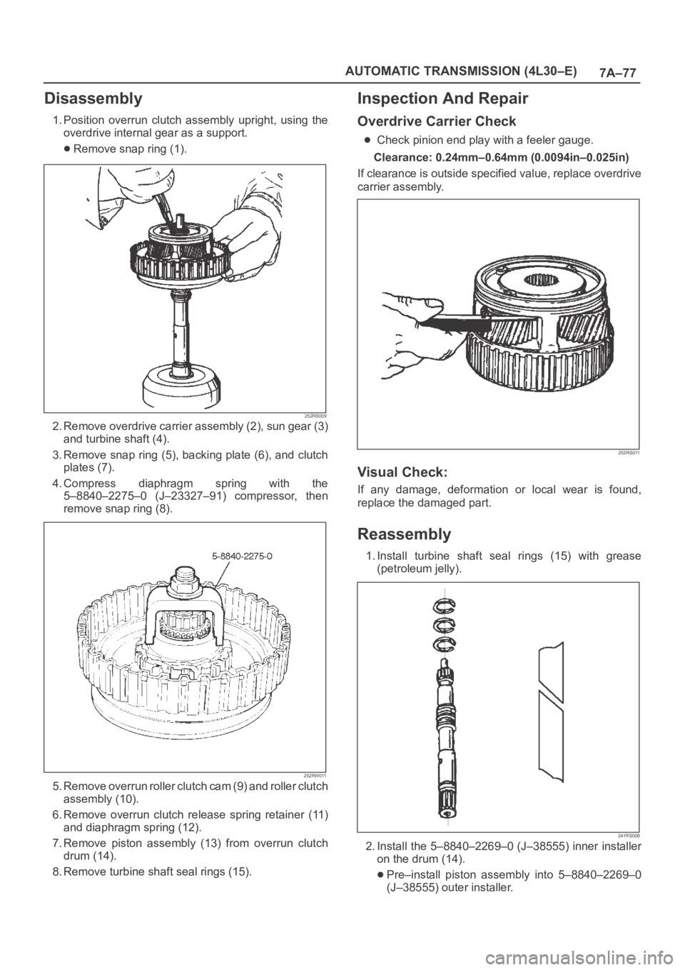
1. Position overrun clutch assembly upright, using the
overdrive internal gear as a support.
Remove snap ring (1).
252RS009
2. Remove overdrive carrier assembly (2), sun gear (3)
and turbine shaft (4).
3. Remove snap ring (5), backing plate (6), and clutch
plates (7).
4. Compress diaphragm spring with the
5–8840–2275–0 (J–23327–91) compressor, then
remove snap ring (8).
252RW011
5 . R e m o v e o v e r r u n r o l l e r c l u t c h c a m ( 9 ) a n d r o l l e r c l u t c h
assembly (10).
6. Remove overrun clutch release spring retainer (11)
and diaphragm spring (12).
7. Remove piston assembly (13) from overrun clutch
drum (14).
8. Remove turbine shaft seal rings (15).
Inspection And Repair
Overdrive Carrier Check
Check pinion end play with a feeler gauge.
Clearance: 0.24mm–0.64mm (0.0094in–0.025in)
If clearance is outside specified value, replace overdrive
carrier assembly.
252RS011
Visual Check:
If any damage, deformation or local wear is found,
replace the damaged part.
Reassembly
1. Install turbine shaft seal rings (15) with grease
(petroleum jelly).
241RS008
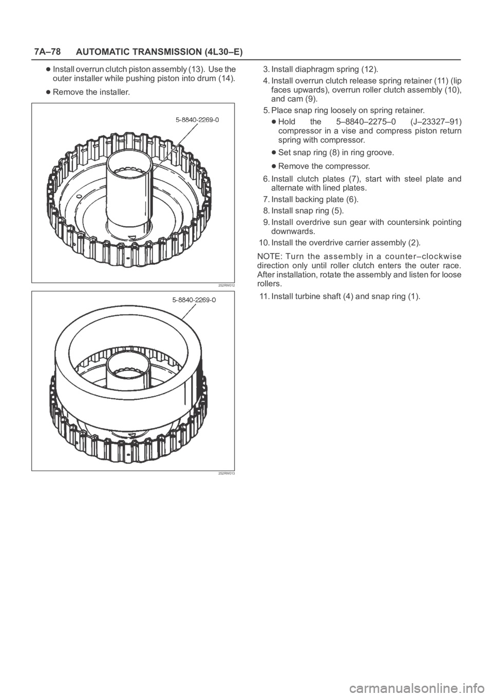
2. Install the 5–8840–2269–0 (J–38555) inner installer
on the drum (14).
Pre–install piston assembly into 5–8840–2269–0
(J–38555) outer installer.
Page 5767 of 6000
7A–78
AUTOMATIC TRANSMISSION (4L30–E)
Install overrun clutch piston assembly (13). Use the
outer installer while pushing piston into drum (14).
Remove the installer.
252RW012
252RW013
3. Install diaphragm spring (12).
4. Install overrun clutch release spring retainer (11) (lip
faces upwards), overrun roller clutch assembly (10),
and cam (9).
5. Place snap ring loosely on spring retainer.
Hold the 5–8840–2275–0 (J–23327–91)
compressor in a vise and compress piston return
spring with compressor.
Set snap ring (8) in ring groove.
Remove the compressor.
6. Install clutch plates (7), start with steel plate and
alternate with lined plates.
7. Install backing plate (6).
8. Install snap ring (5).
9. Install overdrive sun gear with countersink pointing
downwards.
10. Install the overdrive carrier assembly (2).
NOTE: Tu r n t h e a s s e m b l y i n a c o u n t e r – c l o c k w i s e
direction only until roller clutch enters the outer race.
After installation, rotate the assembly and listen for loose
rollers.
11. Install turbine shaft (4) and snap ring (1).
Page 5779 of 6000
7A–90
AUTOMATIC TRANSMISSION (4L30–E)
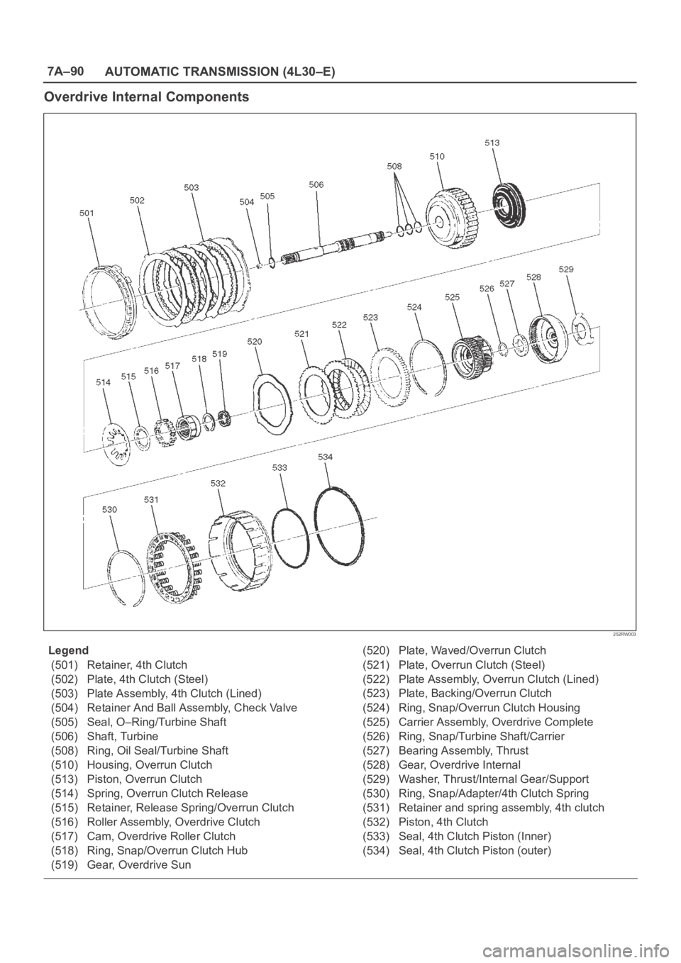
Overdrive Internal Components
252RW003
Legend
(501) Retainer, 4th Clutch
(502) Plate, 4th Clutch (Steel)
(503) Plate Assembly, 4th Clutch (Lined)
(504) Retainer And Ball Assembly, Check Valve
(505) Seal, O–Ring/Turbine Shaft
(506) Shaft, Turbine
(508) Ring, Oil Seal/Turbine Shaft
(510) Housing, Overrun Clutch
(513) Piston, Overrun Clutch
(514) Spring, Overrun Clutch Release
(515) Retainer, Release Spring/Overrun Clutch
(516) Roller Assembly, Overdrive Clutch
(517) Cam, Overdrive Roller Clutch
(518) Ring, Snap/Overrun Clutch Hub
(519) Gear, Overdrive Sun(520) Plate, Waved/Overrun Clutch
(521) Plate, Overrun Clutch (Steel)
(522) Plate Assembly, Overrun Clutch (Lined)
(523) Plate, Backing/Overrun Clutch
(524) Ring, Snap/Overrun Clutch Housing
(525) Carrier Assembly, Overdrive Complete
(526) Ring, Snap/Turbine Shaft/Carrier
(527) Bearing Assembly, Thrust
(528) Gear, Overdrive Internal
(529) Washer, Thrust/Internal Gear/Support
(530) Ring, Snap/Adapter/4th Clutch Spring
(531) Retainer and spring assembly, 4th clutch
(532) Piston, 4th Clutch
(533) Seal, 4th Clutch Piston (Inner)
(534) Seal, 4th Clutch Piston (outer)
Page 5790 of 6000

AUTOMATIC TRANSMISSION (AW30-40LE) 7A–9
MAJOR INPUT/OUTPUT COMPONENTS
Component Function
Input
Vehicle speed sensor (Speedometer) Detects the vehicle speed (Back-up sensor of output
revolution sensor).
Output revolution sensor (Transmission) Detects the vehicle speed.
Input revolution sensor (Transmission) Detects the input revolution (O/D direct clutch drum
revolution).
Engine revolution sensor Detects the engine revolution.
Throttle position sensor Detects the throttle opening rate.
Neutral start switch Detects the select lever position.
Pattern select switch Detects whether the driver has selected "NORMAL",
"POWER", or "WINTER" mode.
Overdrive off switch Detects whether the driver has selected O/D.
Brake lamp switch Detects whether the driver has pressed the brake pedal or
not.
Oil temperature sensor Detects the oil temperature.
Diagnostic star t switch Star ts self-diagnosis and displays a code for faulty part if
any.
Input/Output
Data link connector When connected with Tech2 or tester, can communicate
the data for function check, etc.
Output
Shift solenoid S1, S2 Selects shift point and gear position suited to the vehicle
running condition on the basis of TCM output.
Lock-up control solenoid SL Control the lock-up clutch suited to the vehicle running
condition on the basis of TCM output.
Pressure control solenoid STH Adjusts throttle pressure by energizing current of linear
pressure control solenoid to prevent the shift shock and to
obtain shift smoothly.
"CHECK TRANS" lamp When trouble has occurred to throttle position sensor,
vehicle speed sensor, or solenoid, "CHECK TRANS" lamp
is blinked to warn the driver. If also displays the trouble
code.
A/T OIL TEMP warning lamp Lights when ATF oil temperature rises. (Turned on at
greater than 146
C . Turned off at less than 126C.
Power mode lamp Informs the driver whether the vehicle is in power mode or
not.
Winter mode lamp Informs the driver whether the vehicle is in winter mode or
not.
Computer
Transmission Control Module (TCM) Based on the signal from each switch and sensors, judges
necessary shift point and lock-up operation, and send
signal to each solenoid.
Page 5799 of 6000
7A–18 AUTOMATIC TRANSMISSION (AW30-40LE)
901RW176
F07RW033
740RY00013
740RY00014
901RY00014
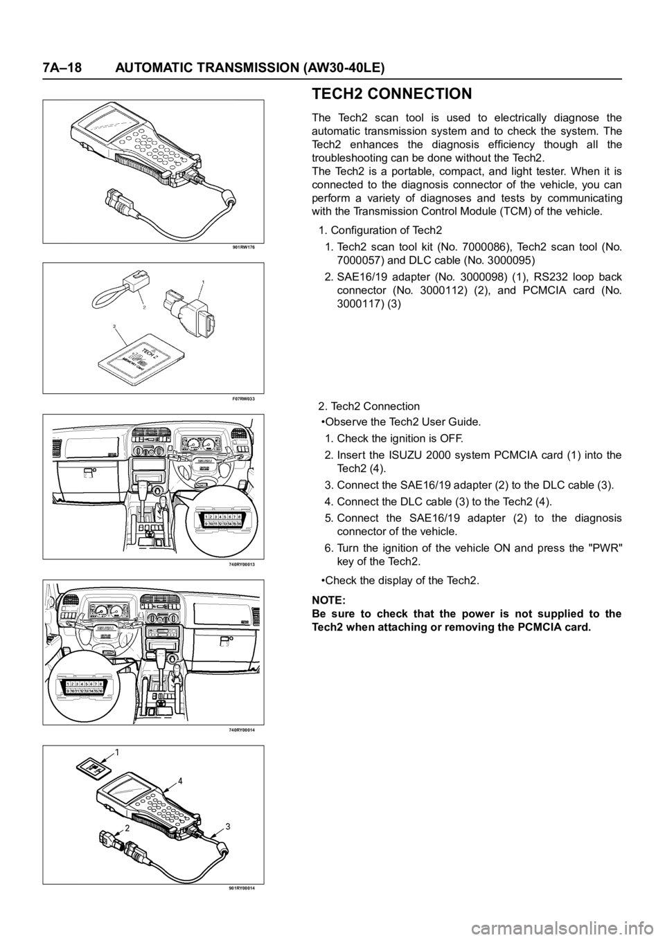
TECH2 CONNECTION
The Tech2 scan tool is used to electrically diagnose the
automatic transmission system and to check the system. The
Tech2 enhances the diagnosis efficiency though all the
troubleshooting can be done without the Tech2.
The Tech2 is a portable, compact, and light tester. When it is
connected to the diagnosis connector of the vehicle, you can
perform a variety of diagnoses and tests by communicating
with the Transmission Control Module (TCM) of the vehicle.
1. Configuration of Tech2
1. Tech2 scan tool kit (No. 7000086), Tech2 scan tool (No.
7000057) and DLC cable (No. 3000095)
2. SAE16/19 adapter (No. 3000098) (1), RS232 loop back
connector (No. 3000112) (2), and PCMCIA card (No.
3000117) (3)
2. Tech2 Connection
•Observe the Tech2 User Guide.
1. Check the ignition is OFF.
2. Inser t the ISUZU 2000 system PCMCIA card (1) into the
Te c h 2 ( 4 ) .
3. Connect the SAE16/19 adapter (2) to the DLC cable (3).
4. Connect the DLC cable (3) to the Tech2 (4).
5. Connect the SAE16/19 adapter (2) to the diagnosis
connector of the vehicle.
6. Turn the ignition of the vehicle ON and press the "PWR"
key of the Tech2.
•Check the display of the Tech2.
NOTE:
Be sure to check that the power is not supplied to the
Tech2 when attaching or removing the PCMCIA card.