Page 659 of 6000

DRIVE LINE CONTROL SYSTEM (TOD) 4B2–88
StepActionYe sNo
1Are the front and rear tires in specified size?
Go to Step 2
Replace the tires
with specified
ones, and service
the new tires.
Go to Step 16
2Is the tire pressure correct?
Go to Step 3
Replace the tires
with specified
ones, and service
the new tires.
Go to Step 16
3Are the tires free from abnormal wear?
Go to Step 4
Replace the tires
with specified
ones, and service
the new tires.
Go to Step 16
4Are different types of tires used?
Go to Step 5
Replace the tires
with specified
ones, and service
the new tires.
Go to Step 16
51. Start the engine.
2. Shift the transfer lever to the high (TOD) position.
3. Fully turn the steering to the left (or right) end, and select the D
range and start the creep run.
Does the tight corner braking occur? Is the judder with chug-chug
sound observed? * Use caution on the operation.
Go to Step 6 Go to Step 11
61. Shift the transfer lever to the 2H position.
2. Fully turn the steering to the left (or right) end, and select the D
range and start the creep run.
Does the tight corner braking occur? Is the judder with chug-chug
sound observed? * Use caution on the operation.
Go to Step 7 Go to Step 14
7Is an LSD mounted to the rear differential? Go to Step 8 Go to Step 9
8Is the genuine LSD oil used in the rear differential?
Go to Step 9
Replace the
differential oil.
Go to Step 16
9Does the engine output the power correctly?
Go to Step 10
Check the
engine.
Go to Step 16
10Do the speed sensors work correctly? (Check trouble codes.)The ECU has
failed. Replace
the ECU.
Go to Step 16
Replace the
speed sensors.
Go to Step 16
11Is the tight corner braking observed only when the brake is
applied?
Go to Step 12
Conduct full
steering under
WOT.
Go to Step 5
121. Turn off the starter switch.
2. Disconnect the ECU connector.
Is the battery voltage observed between terminals (B–68)6 and
(B–67)11?
Go to Step 13
Repair the circuit
of terminal 6
(ABS IN).
Go to Step 16
Page 713 of 6000
4C–47 DRIVE SHAFT SYSTEM
Main Data and Specifications
General Specifications
Engine6VE1 (3.5L)6VD1 (3.2L)4JX1 (3.0L)4JG2 (3.1L)
Transmission
M/TA/T
A/T
with
TOD
M/TA/T
A/T
with
TOD
M/TA/TM/TA/T
Construction
Hollow steel tube
with yoke and
spider type
universal joint
Hollow
steel
tube
with
consta
nt
velocity
joints
Hollow steel tube
with yoke and
spider type
universal joint
Hollow
steel
tube
with
consta
nt
velocity
joints
Hollow steel tube with yoke and
spider type universal joint
Outside
diameter40.0mm (1.57 in)
Length559mm
(22.01in)559mm
(22.01in)577mm
(22.72in)393mm
(15.47in)559mm
(22.01in)577mm
(22.72in)627mm
(24.69in)627mm
(24.69in)421mm
(16.57in)627mm
(24.69in)
Torque Specifications
E04RW021
Page 721 of 6000
4C–55 DRIVE SHAFT SYSTEM
Main Data and Specifications
General Specifications
Engine6VE1 (3.5L)6VD1 (3.2L)4JX1 (3.0L)4JG2 (3.1L)
Transmission
M/TA/T
A/T
with
TOD
M/TA/T
A/T
with
TOD
M/TA/TM/TA/T
ConstructionHollow steel tube with yoke and spider type universal joint
LengthS
W
B
668mm (26.30in)—846mm
(33.31in)678mm
(26.69in)—604mm (23.78in)810mm
(31.89in)—
L
W
B
1093mm (43.03in)1075mm
(42.32in)1271mm
(50.04in)1103mm
(43.43in)1083mm
(42.64in)1029mm (40.51in)1236mm
(48.66in)1037mm
(40.83in)
Outside
diamterS
W
B
68.9mm (2.71in)—68.9mm (2.71in)—68.9mm (2.71in)—
LW
B68.9mm (2.71in)82.6mm
(3.25in)68.9mm (2.71in)82.6mm
(3.25in)68.9mm
(2.71in)
Torque Specifications
E04RW023
Page 729 of 6000

4D1–8
TRANSFER CASE (STANDARD TYPE)
Transfer Rear Oil Seal
Removal
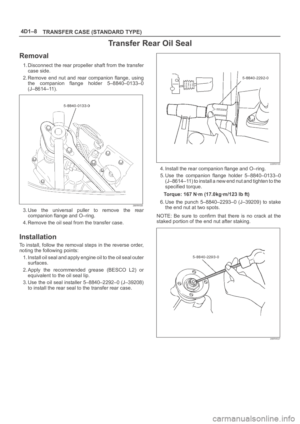
1. Disconnect the rear propeller shaft from the transfer
case side.
2. Remove end nut and rear companion flange, using
the companion flange holder 5–8840–0133–0
(J–8614–11).
266RW026
3. Use the universal puller to remove the rear
companion flange and O–ring.
4. Remove the oil seal from the transfer case.
Installation
To install, follow the removal steps in the reverse order,
noting the following points:
1. Install oil seal and apply engine oil to the oil seal outer
surfaces.
2. Apply the recommended grease (BESCO L2) or
equivalent to the oil seal lip.
3. Use the oil seal installer 5–8840–2292–0 (J–39208)
to install the rear seal to the transfer rear case.
220RW105
4. Install the rear companion flange and O–ring.
5. Use the companion flange holder 5–8840–0133–0
(J–8614–11) to install a new end nut and tighten to the
specified torque.
Torque: 167 Nꞏm (17.0kgꞏm/123 lb ft)
6. Use the punch 5–8840–2293–0 (J–39209) to stake
the end nut at two spots.
NOTE: Be sure to confirm that there is no crack at the
staked portion of the end nut after staking.
266RW027
Page 738 of 6000

TRANSFER CASE (STANDARD TYPE)
4D1–17
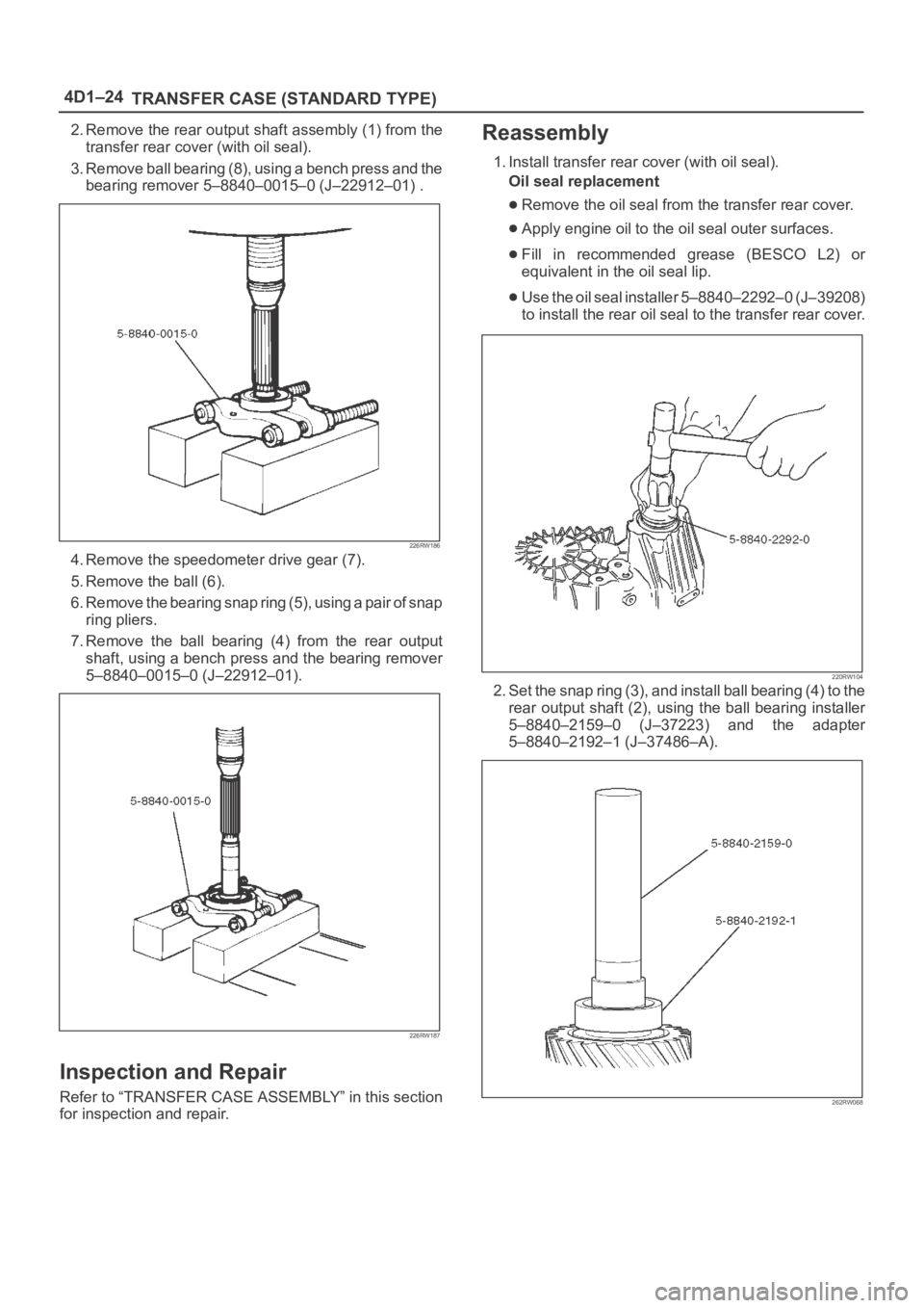
2. Remove the rear output shaft assembly (1) from the
transfer rear cover (with oil seal).
3. Remove ball bearing (8), using a bench press and the
bearing remover 5–8840–0015–0 (J–22912–01) .
226RW186
4. Remove the speedometer drive gear (7).
5. Remove the ball (6).
6. Remove the bearing snap ring (5), using a pair of snap
ring pliers.
7. Remove the ball bearing (4) from the rear output
shaft, using a bench press and the bearing remover
5–8840–0015–0 (J–22912–01).
226RW187
Inspection and Repair
Refer to “TRANSFER CASE ASSEMBLY” in this section
for inspection and repair.
Reassembly
1. Install transfer rear cover (with oil seal).
Oil seal replacement
Remove the oil seal from the transfer rear cover.
Apply engine oil to the oil seal outer surfaces.
Fill in recommended grease (BESCO L2) or
equivalent in the oil seal lip.
Use the oil seal installer 5–8840–2292–0 (J–39208)
to install the rear oil seal to the transfer rear cover.
220RW104
2. Set the snap ring (3), and install ball bearing (4) to the
rear output shaft (2), using the ball bearing installer
5–8840–2159–0 (J–37223) and the adapter
5–8840–2192–1 (J–37486–A).
262RW068
Page 745 of 6000

4D1–24
TRANSFER CASE (STANDARD TYPE)
2. Remove the rear output shaft assembly (1) from the
transfer rear cover (with oil seal).
3. Remove ball bearing (8), using a bench press and the
bearing remover 5–8840–0015–0 (J–22912–01) .
226RW186
4. Remove the speedometer drive gear (7).
5. Remove the ball (6).
6. Remove the bearing snap ring (5), using a pair of snap
ring pliers.
7. Remove the ball bearing (4) from the rear output
shaft, using a bench press and the bearing remover
5–8840–0015–0 (J–22912–01).
226RW187
Inspection and Repair
Refer to “TRANSFER CASE ASSEMBLY” in this section
for inspection and repair.
Reassembly
1. Install transfer rear cover (with oil seal).
Oil seal replacement
Remove the oil seal from the transfer rear cover.
Apply engine oil to the oil seal outer surfaces.
Fill in recommended grease (BESCO L2) or
equivalent in the oil seal lip.
Use the oil seal installer 5–8840–2292–0 (J–39208)
to install the rear oil seal to the transfer rear cover.
220RW104
2. Set the snap ring (3), and install ball bearing (4) to the
rear output shaft (2), using the ball bearing installer
5–8840–2159–0 (J–37223) and the adapter
5–8840–2192–1 (J–37486–A).
262RW068
Page 758 of 6000
TRANSFER CASE (STANDARD TYPE)
4D1–37
Reassembly
1. Put the transfer case (with oil seal) as the following
illustration.
Input shaft oil seal (1) replacement
1. Remove the oil seal from the transfer case.
2. Apply engine oil to the oil seal outer surfaces.
3. Apply recommended grease (BESCO L2) or
equivalent to the oil seal lip.
4. Use the oil seal installer 5–8840–2279–0
(J–38592) to install the oil seal to the transfer
case.
220RW106
Front output shaft oil seal (2) replacement
1. Remove the oil seal from the transfer case.
2. Apply engine oil to the oil seal outer surfaces.
3. Apply recommended grease (BESCO L2) or
equivalent to the oil seal lip.
4. Use the oil seal installer 5–8840–2281–0
(J–38594) to install the oil seal to the transfer
case.
220RW107
Legend
(2) Front output shaft oil seal
2. Apply chassis grease (3) to the sub–gear (23) and the
counter gear (22) thrust surfaces.
226RW134
Page 761 of 6000
4D1–40
TRANSFER CASE (STANDARD TYPE)
21. Apply engine oil to the thrust surfaces of the sub–gear
(13), the belleville spring (14), and the spacer (15).
(M/T)
262RW060
22. Install the sub–gear (anti–lash plate) (13), belleville
spring (14), and spacer (15) to the front output gear
(11).(M/T)
23. Install the sub–gear snap ring (16). (M/T)
24. Use a bench press to install the needle bearing collar
(17) together with the front output gear, aligning inside
ring claw with block ring groove.
262RS014
25. Install ball bearing (18), using a bench press.26. Select a snap ring that will allow the minimum axial
play.
Clearance : 0–0.1 mm (0–0.004 in)
Snap ring availability:
Snap ring thicknessColor coding
1.55 mm (0.061 in)White
1.60 mm (0.063 in)Ye l l o w
1.65 mm (0.065 in)Blue
1.70 mm (0.067 in)Pink
1.75 mm (0.069 in)Green
1.80 mm (0.071 in)Brown
1.85 mm (0.073 in)Red
1.90 mm (0.075 in)Orange
262RS015
226RS021