Page 2861 of 6000

STEP ACTION VALUE(S) YES NO
Is B–1 grounded securely?
Disconnect the front power window & door lock switch–LH
connector D–14.
Is there continuity between harness side connector D–14
terminal 7 and the ground B–1?
Repair an open circuit between connector D–14 terminal 7
and the ground B–1.
Is the action complete?
Turn the starter switch on.
Is the battery voltage applied between harness side
connector D–14 terminal 5 and the ground?
Repair an open circuit between connector B–37 terminal 4
and connector D–14 terminal 5.
Is the action complete?
Connect the battery positive terminal with harness side
connector D–14 terminal 10 or 1, and connect the battery
negative terminal with harness side connector D–14 terminal
1 or 10.
Does the motor operate?
1. Disconnect the front power window motor–LH connector
D–11.
2. Connect the battery positive terminal with the motor side
connector D–11 terminal 1 or 2, and connect the battery
negative terminal with the motor side connector D–11
terminal 2 or 1.
Does the motor operate?
Repair an open circuit between the front power window &
door lock switch–LH and the front power window motor–LH.
Is the action complete?–
–
–
Approx. 12V
–
–
–
–Go to
step 2
Go to
step 4
Go to
step 2
Go to
step 6
Go to
step 4
Replace
the front
power
window &
door lock
switch–LH
Go to
step 8
Verify
repairGround it
securely
Go to
step 3
–
Go to
step 5
–
Go to
step 7
Replace
the motor
– 1
2
3
4
5
6
7
8
Page 2862 of 6000

STEP ACTION VALUE(S) YES NO
1. Disconnect the rear power window switch–LH connector
D–22 or the rear power window & door lock switch–RH
connector D–27.
2. Turn the starter switch on.
Is the battery voltage applied between harness side
connector D–22 terminal 4 and the ground, or harness side
connector D–27 terminal 4 and the ground?
Repair an open circuit between connector B–37 terminal 4
and connector D–22 terminal 4 or connector D–27 terminal 4.
Is the action complete?
Is there continuity between harness side connector D–22
terminal 3 and the ground, or harness side connector
D–27 terminal 3 and the ground?
Repair an open circuit between connector D–22 terminal 3 or
connector D–27 terminal 3 and the ground.
Is the action complete?
Connect the battery positive terminal with harness side
connector D–22 terminals 5 or harness side connector D–27
terminal 5, and connect the battery negative terminal with
harness side connector D–22 terminal 6 or harness side
connector D–27 terminal 6.
Does the motor operate?
1. Disconnect the rear power window motor connector D–20
or D–25.
2. Connect the battery positive terminal with motor side
connector D–20 or D–25 terminal 1 or 2, and connect the
battery negative terminal with the motor side connector
D–20 or D–25 terminal 2 or 1.
Does the motor operate?
Repair an open circuit between the rear power window
switch and the rear power window motor.
Is the action complete?Approx. 12V
–
–
–
–
–
–Go to
step 3
Go to
step 1
Go to
step 5
Go to
step 3
Replace
the rear
power
window
switch–LH
or –RH
Go to
step 7
Verify
repairGo to
step 2
–
Go to
step 4
–
Go to
step 6
Replace
the motor
– 1
2
3
4
5
6
7
Page 2875 of 6000

DTC 1–3 Mechanical Defect
STEP ACTION VALUE(S) YES NO
1. Turn the starter switch off.
2. Disconnect the actuator connector C–37.
3. Connect the battery positive terminal with the actuator side
connector terminal 3 and the battery negative terminal with
terminal 4.
Does the control plate move by hand?
Connect the battery positive terminal with the actuator side
connector terminal 1 and 3, and the battery negative terminal
with terminal 2 and 4.
Does the control plate move to full open side?
Connect the battery positive terminal with the actuator side
connector terminal 2 and 3, and the battery negative terminal
with terminal 1 and 4.
Does the control plate move to full close side?
Is there continuity between harness side connector C–37
terminal 1 and connector B–9 terminal 7, connector C–37
terminal 2 and connector B–9 terminal 15?–
–
–
–Replace
the
actuator
Go to
step 3
Go to
step 4
Replace
the control
unitGo to
step 2
Replace
the
actuator
Replace
the
actuator
Repair or
replace
harness 1
2
3
4
Page 2878 of 6000
2.0
Y/G2.0
W/G 3.0
W/G
0.5
LG FL-6 40A
ABS
F-9 20A
ABS
INDICATOR
LIGHT(METER)
BRAKE
SW STOP
LIGHT
SW
ELECTRONIC
HYDRAULIC
CONTROL UNIT
4WD CONTROL
UNIT(19)
14C-413C-4
3.0
B/Y3.0
B/Y
0.85
L/W0.5
L/W0.5
L/W
2.0
BC-4 10A
ELEC.IGN.
STARTER SW
(IG1)STARTER SW
(IG1)
C-10 10A
METER,GAUGE
I-9I-10156
I-9
2
H-26
H-1619
H-2718 16
5.0
W
0.85
G/W C-14 15A
STOP,A/T CONT. BATT.(+) BATT.(+)
STOP LIGHT
10C-430.85
G/W (W/CRUISE CONTROL) 0.85
G/W
0.85
G/Y
0.85
G/Y 0.85
G/Y
0.85
G/Y
B-131
B-13
4
B-14
H-131
B-14
2G-
SENSOR
26C-4 0.5
L/W
0.5
Y/B
0.5
Y/B
B-252
B-25
1
H-151
8C-4
6
C-39
FENDER-RH
H-131
C-4
15
16C-4 0.5
L/Y
0.5
L/Y
0.5
Y
0.5
Y
A
2.0
B(DIESEL)
5
C-39
FENDER-RH
C-4
15
2.0
B
C-85
ENG.ROOM-FRT
C-4 GROUND GROUND GROUND BATTERY BATTERY G-SENSOR POWER
SUPPLYSILA BRAKE LIGHT
SWITCH
12
4WDABS
D08RW601
Page 2885 of 6000
2.0
Y/G2.0
W/G 3.0
W/G
0.5
LG FL-6 40A
ABS
F-9 20A
ABS
INDICATOR
LIGHT(METER)
BRAKE
SWITCH STOP
LIGHT
SWITCH
ELECTRONIC
HYDRAULIC
CONTROL
UNIT
4WD CONTROL
UNIT(19)
14C-413C-4
3.0
B/Y3.0
B/Y
0.85
L/W0.5
L/W0.5
L/W
2.0
BC-4 10A
ELEC.IGN.
STARTER SW
(IG1)STARTER SW
(IG1)
C-10 10A
METER,GAUGE
I-9I-1015 10
I-9
18
H-25
H-1622
H-2518 16
5.0
W
0.85
G/W C-14 15A
STOP,A/T CONT. BATT.(+) BATT.(+)
STOP LIGHT
10C-420.85
G/W (W/CRUISE CONTROL) 0.85
G/W
0.85
G/Y
0.85
G/Y 0.85
G/Y
0.85
G/Y
B-131
B-13
4
B-14
H-131
B-14
2
G-
SENSOR
26C-4 0.5
L/W
0.5
Y/B
0.5
Y/B
B-252
B-25
1
H-154
8C-4
6
C-39
FENDER-RH
H-125
C-4
15
16C-4 0.5
L/Y
0.5
L/Y
0.5
Y
0.5
Y
A
2.0
B
C-85
ENG. ROOM-FRT
C-4 GROUND GROUND BATTERY BATTERY G-SENSOR POWER
SUPPLYSILA BRAKE LIGHT
SWITCH
12
4WDABS
2.0
B
5
C-39
FENDER-RH
C-4
15GROUND
(4JG2)
D08RW793
Page 2992 of 6000

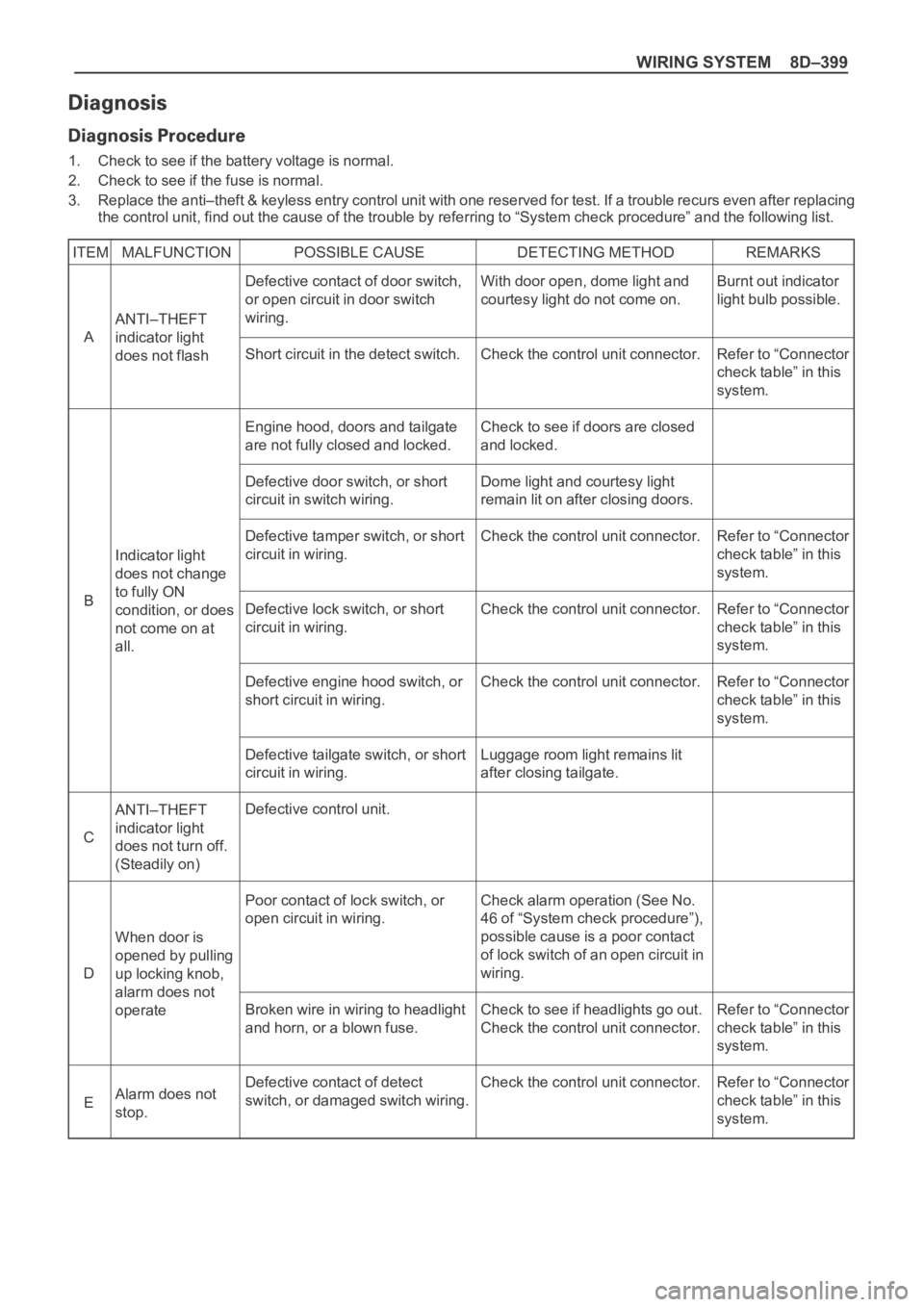
WIRING SYSTEM 8D–399
1. Check to see if the battery voltage is normal.
2. Check to see if the fuse is normal.
3. Replace the anti–theft & keyless entry control unit with one reserved for test. If a trouble recurs even after replacing
the control unit, find out the cause of the trouble by referring to “System check procedure” and the following list.
ITEM MALFUNCTION POSSIBLE CAUSE DETECTING METHOD REMARKS
ANTI–THEFT
indicator light
does not flash
ANTI–THEFT
indicator light
does not turn off.
(Steadily on)
When door is
opened by pulling
up locking knob,
alarm does not
operate
Alarm does not
stop. Indicator light
does not change
to fully ON
condition, or does
not come on at
all.Burnt out indicator
light bulb possible.
Refer to “Connector
check table” in this
system.
Refer to “Connector
check table” in this
system.
Refer to “Connector
check table” in this
system.
Refer to “Connector
check table” in this
system.
Refer to “Connector
check table” in this
system.
Refer to “Connector
check table” in this
system. Defective contact of door switch,
or open circuit in door switch
wiring.
Short circuit in the detect switch.
Engine hood, doors and tailgate
are not fully closed and locked.
Defective door switch, or short
circuit in switch wiring.
Defective tamper switch, or short
circuit in wiring.
Defective lock switch, or short
circuit in wiring.
Defective engine hood switch, or
short circuit in wiring.
Defective tailgate switch, or short
circuit in wiring.
Defective control unit.
Poor contact of lock switch, or
open circuit in wiring.
Broken wire in wiring to headlight
and horn, or a blown fuse.
Defective contact of detect
switch, or damaged switch wiring.With door open, dome light and
courtesy light do not come on.
Check the control unit connector.
Check to see if doors are closed
and locked.
Dome light and courtesy light
remain lit on after closing doors.
Check the control unit connector.
Check the control unit connector.
Check the control unit connector.
Luggage room light remains lit
after closing tailgate.
Check alarm operation (See No.
46 of “System check procedure”),
possible cause is a poor contact
of lock switch of an open circuit in
wiring.
Check to see if headlights go out.
Check the control unit connector.
Check the control unit connector. A
C
D
E B
Page 2998 of 6000

WIRING SYSTEM 8D–405
TERMINAL
CONNECTIONCHECK
OPERATIONCIRCUIT
NO. ITEM CONDITION
1 FRT door switch–LH, RH ContinuityOpen door Continuity
Close door No continuity
2 RR door switch–LH, RH ContinuityOpen door Continuity
Close door No continuity
3— — – –
4 Door lock key switch–LH, RH Continuity Lock with key Continuity
5 FRT door lock switch–LH, RH Continuity Lock Continuity
6 Tailgate switch ContinuityOpen tailgate Continuity
Close tailgate No continuity
8 Anti–theft horn Voltage – Approx. 12V
10 Battery Voltage – Approx. 12V
11 Door switch ContinuityUnlock with locking knob Continuity
Lock with locking knob No continuity
12 Engine hood switch ContinuityOpen engine hood Continuity
Close engine hood No continuity
13 Detect switch ContinuityUnlock with key Continuity
Lock with key No continuity
14 Door lock key switch Continuity Unlock Continuity
15 FRT door lock switch–LH, RH Continuity Unlock Continuity
16 Tamper switch Continuity – No continuity
17 Ground Continuity – Continuity
18 Starter switch Voltage Starter switch “ACC” Approx. 12V
19 Indicator light Voltage – Approx. 12V
20 Dome light Voltage Dome light “DOOR” position Approx. 12V
21 Anti-theft relay Voltage – Approx. 12V
22 Starter relay VoltageMode switch “P” or “N” Approx. 12V
Clutch pedal depressed Approx. 12V
Check the anti–theft & keyless entry control unit harness side connector B–20 by using a circuit tester.
Page 3186 of 6000

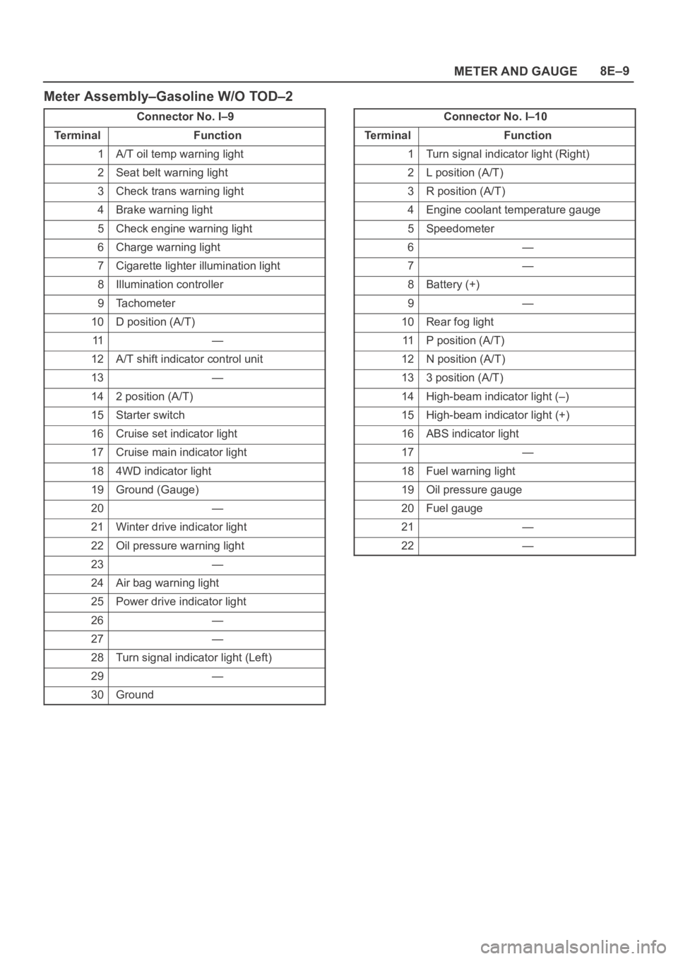
METER AND GAUGE8E–9
Meter Assembly–Gasoline W/O TOD–2
Connector No. I–9
Te r m i n a lFunction
1A/T oil temp warning light
2Seat belt warning light
3Check trans warning light
4Brake warning light
5Check engine warning light
6Charge warning light
7Cigarette lighter illumination light
8Illumination controller
9Tachometer
10D position (A/T)
11—
12A/T shift indicator control unit
13—
142 position (A/T)
15Starter switch
16Cruise set indicator light
17Cruise main indicator light
184WD indicator light
19Ground (Gauge)
20—
21Winter drive indicator light
22Oil pressure warning light
23—
24Air bag warning light
25Power drive indicator light
26—
27—
28Turn signal indicator light (Left)
29—
30Ground
Connector No. I–10
Te r m i n a lFunction
1Turn signal indicator light (Right)
2L position (A/T)
3R position (A/T)
4Engine coolant temperature gauge
5Speedometer
6—
7—
8Battery (+)
9—
10Rear fog light
11P position (A/T)
12N position (A/T)
133 position (A/T)
14High-beam indicator light (–)
15High-beam indicator light (+)
16ABS indicator light
17—
18Fuel warning light
19Oil pressure gauge
20Fuel gauge
21—
22—