1998 OPEL FRONTERA check oil
[x] Cancel search: check oilPage 5538 of 6000
6E–109 4JX1–TC ENGINE DRIVEABILITY AND EMISSIONS
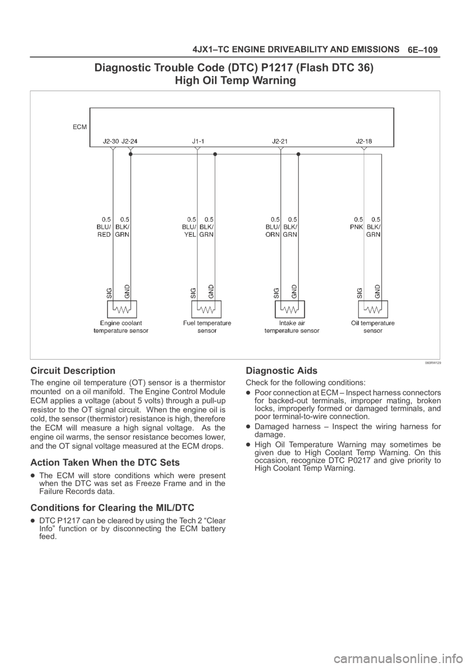
Diagnostic Trouble Code (DTC) P1217 (Flash DTC 36)
High Oil Temp Warning
060RW129
Circuit Description
The engine oil temperature (OT) sensor is a thermistor
mounted on a oil manifold. The Engine Control Module
ECM applies a voltage (about 5 volts) through a pull-up
resistor to the OT signal circuit. When the engine oil is
cold, the sensor (thermistor) resistance is high, therefore
the ECM will measure a high signal voltage. As the
engine oil warms, the sensor resistance becomes lower,
and the OT signal voltage measured at the ECM drops.
Action Taken When the DTC Sets
The ECM will store conditions which were present
when the DTC was set as Freeze Frame and in the
Failure Records data.
Conditions for Clearing the MIL/DTC
DTC P1217 can be cleared by using the Tech 2 “Clear
Info” function or by disconnecting the ECM battery
feed.
Diagnostic Aids
Check for the following conditions:
Poor connection at ECM – Inspect harness connectors
for backed-out terminals, improper mating, broken
locks, improperly formed or damaged terminals, and
poor terminal-to-wire connection.
Damaged harness – Inspect the wiring harness for
damage.
High Oil Temperature Warning may sometimes be
given due to High Coolant Temp Warning. On this
occasion, recognize DTC P0217 and give priority to
High Coolant Temp Warning.
Page 5539 of 6000
6E–110
4JX1–TC ENGINE DRIVEABILITY AND EMISSIONS
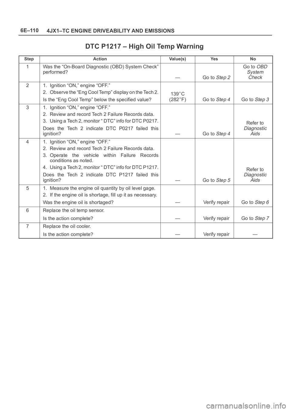
DTC P1217 – High Oil Temp Warning
StepActionVa l u e ( s )Ye sNo
1Was the “On-Board Diagnostic (OBD) System Check”
performed?
—Go to Step 2
Go to OBD
System
Check
21. Ignition “ON,” engine “OFF.”
2. Observe the “Eng Cool Temp” display on the Tech 2.
Is the “Eng Cool Temp” below the specified value?
139C
(282
F)Go to Step 4Go to Step 3
31. Ignition “ON,” engine “OFF.”
2. Review and record Tech 2 Failure Records data.
3. Using a Tech 2, monitor “ DTC” info for DTC P0217.
Does the Tech 2 indicate DTC P0217 failed this
ignition?
—Go to Step 4
Refer to
Diagnostic
Aids
41. Ignition “ON,” engine “OFF.”
2. Review and record Tech 2 Failure Records data.
3. Operate the vehicle within Failure Records
conditions as noted.
4. Using a Tech 2, monitor “ DTC” info for DTC P1217.
Does the Tech 2 indicate DTC P1217 failed this
ignition?
—Go to Step 5
Refer to
Diagnostic
Aids
51. Measure the engine oil quantity by oil level gage.
2. If the engine oil is shortage, fill up it as necessary.
Was the engine oil is shortaged?
—Verify repairGo to Step 6
6Replace the oil temp sensor.
Is the action complete?
—Verify repairGo to Step 7
7Replace the oil cooler.
Is the action complete?
—Verify repair—
Page 5546 of 6000
6E–117 4JX1–TC ENGINE DRIVEABILITY AND EMISSIONS
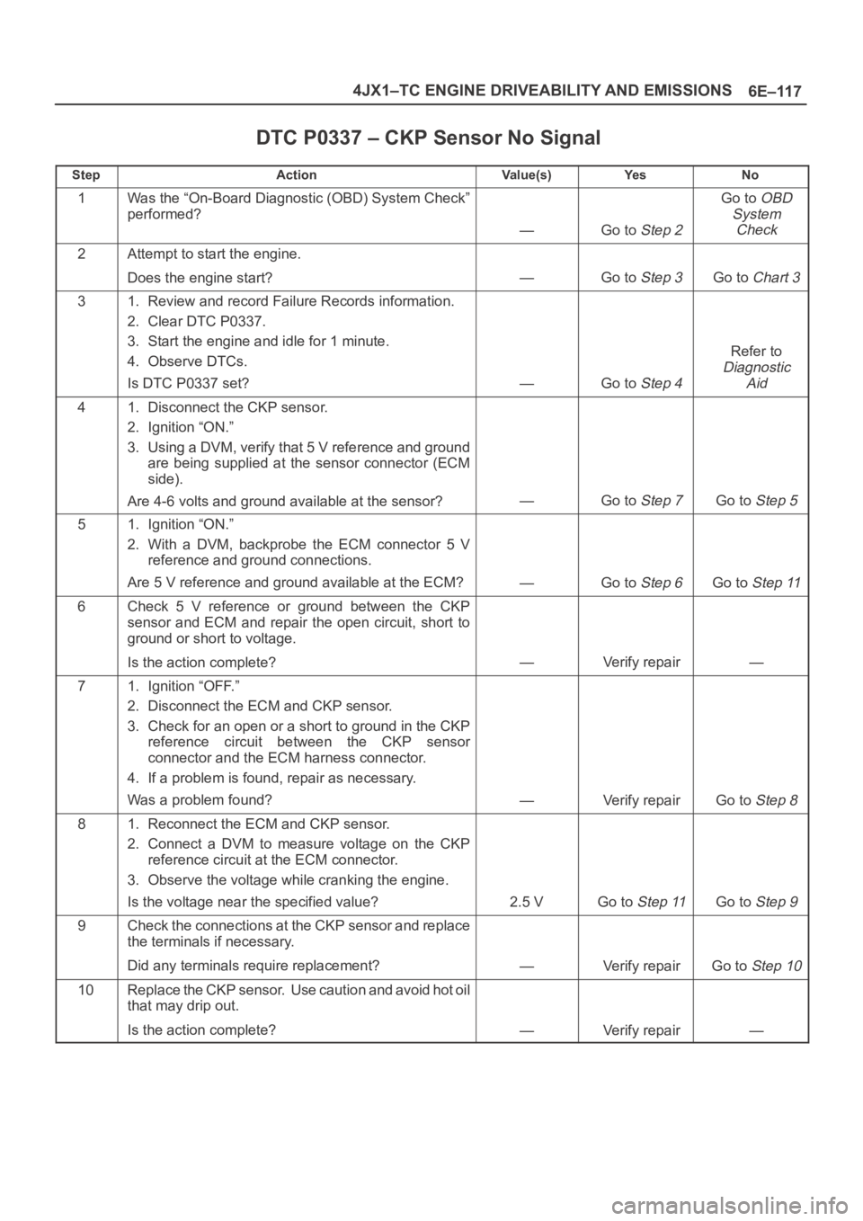
DTC P0337 – CKP Sensor No Signal
StepActionVa l u e ( s )Ye sNo
1Was the “On-Board Diagnostic (OBD) System Check”
performed?
—Go to Step 2
Go to OBD
System
Check
2Attempt to start the engine.
Does the engine start?
—Go to Step 3Go to Chart 3
31. Review and record Failure Records information.
2. Clear DTC P0337.
3. Start the engine and idle for 1 minute.
4. Observe DTCs.
Is DTC P0337 set?
—Go to Step 4
Refer to
Diagnostic
Aid
41. Disconnect the CKP sensor.
2. Ignition “ON.”
3. Using a DVM, verify that 5 V reference and ground
are being supplied at the sensor connector (ECM
side).
Are 4-6 volts and ground available at the sensor?
—Go to Step 7Go to Step 5
51. Ignition “ON.”
2. With a DVM, backprobe the ECM connector 5 V
reference and ground connections.
Are 5 V reference and ground available at the ECM?
—Go to Step 6Go to Step 11
6Check 5 V reference or ground between the CKP
sensor and ECM and repair the open circuit, short to
ground or short to voltage.
Is the action complete?
—Verify repair—
71. Ignition “OFF.”
2. Disconnect the ECM and CKP sensor.
3. Check for an open or a short to ground in the CKP
reference circuit between the CKP sensor
connector and the ECM harness connector.
4. If a problem is found, repair as necessary.
Was a problem found?
—Verify repairGo to Step 8
81. Reconnect the ECM and CKP sensor.
2. Connect a DVM to measure voltage on the CKP
reference circuit at the ECM connector.
3. Observe the voltage while cranking the engine.
Is the voltage near the specified value?
2.5 VGo to Step 11Go to Step 9
9Check the connections at the CKP sensor and replace
the terminals if necessary.
Did any terminals require replacement?
—Verify repairGo to Step 10
10Replace the CKP sensor. Use caution and avoid hot oil
that may drip out.
Is the action complete?
—Verify repair—
Page 5606 of 6000
6E–177 4JX1–TC ENGINE DRIVEABILITY AND EMISSIONS
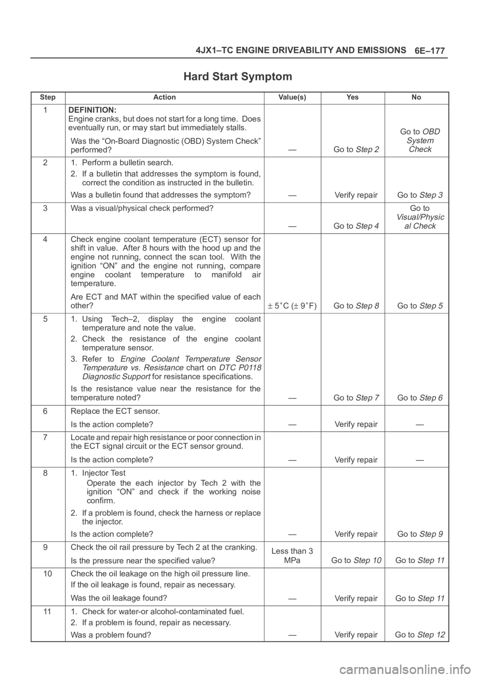
Hard Start Symptom
StepActionVa l u e ( s )Ye sNo
1DEFINITION:
Engine cranks, but does not start for a long time. Does
eventually run, or may start but immediately stalls.
Was the “On-Board Diagnostic (OBD) System Check”
performed?
—Go to Step 2
Go to OBD
System
Check
21. Perform a bulletin search.
2. If a bulletin that addresses the symptom is found,
correct the condition as instructed in the bulletin.
Was a bulletin found that addresses the symptom?
—Verify repairGo to Step 3
3Was a visual/physical check performed?
—Go to Step 4
Go to
Visual/Physic
al Check
4Check engine coolant temperature (ECT) sensor for
shift in value. After 8 hours with the hood up and the
engine not running, connect the scan tool. With the
ignition “ON” and the engine not running, compare
engine coolant temperature to manifold air
temperature.
Are ECT and MAT within the specified value of each
other?
5C ( 9F)Go to Step 8Go to Step 5
51. Using Tech–2, display the engine coolant
temperature and note the value.
2. Check the resistance of the engine coolant
temperature sensor.
3. Refer to
Engine Coolant Temperature Sensor
Temperature vs. Resistance
chart on DTC P0118
Diagnostic Support
for resistance specifications.
Is the resistance value near the resistance for the
temperature noted?
—Go to Step 7Go to Step 6
6Replace the ECT sensor.
Is the action complete?
—Verify repair—
7Locate and repair high resistance or poor connection in
the ECT signal circuit or the ECT sensor ground.
Is the action complete?
—Verify repair—
81. Injector Test
Operate the each injector by Tech 2 with the
ignition “ON” and check if the working noise
confirm.
2. If a problem is found, check the harness or replace
the injector.
Is the action complete?
—Verify repairGo to Step 9
9Check the oil rail pressure by Tech 2 at the cranking.
Is the pressure near the specified value?Less than 3
MPa
Go to Step 10Go to Step 11
10Check the oil leakage on the high oil pressure line.
If the oil leakage is found, repair as necessary.
Was the oil leakage found?
—Verify repairGo to Step 11
111. Check for water-or alcohol-contaminated fuel.
2. If a problem is found, repair as necessary.
Was a problem found?
—Verify repairGo to Step 12
Page 5614 of 6000
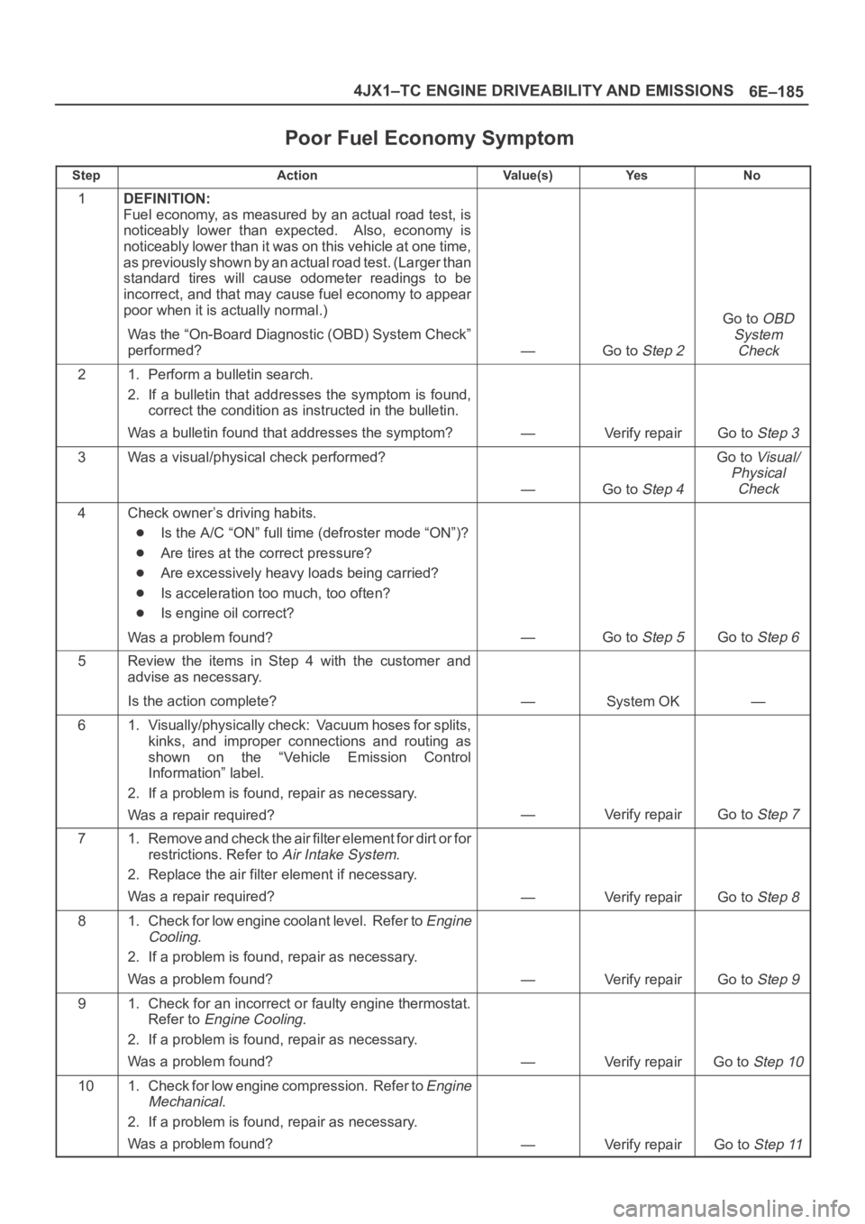
6E–185 4JX1–TC ENGINE DRIVEABILITY AND EMISSIONS
Poor Fuel Economy Symptom
StepActionVa l u e ( s )Ye sNo
1DEFINITION:
Fuel economy, as measured by an actual road test, is
noticeably lower than expected. Also, economy is
noticeably lower than it was on this vehicle at one time,
as previously shown by an actual road test. (Larger than
standard tires will cause odometer readings to be
incorrect, and that may cause fuel economy to appear
poor when it is actually normal.)
Was the “On-Board Diagnostic (OBD) System Check”
performed?
—Go to Step 2
Go to OBD
System
Check
21. Perform a bulletin search.
2. If a bulletin that addresses the symptom is found,
correct the condition as instructed in the bulletin.
Was a bulletin found that addresses the symptom?
—Verify repairGo to Step 3
3Was a visual/physical check performed?
—Go to Step 4
Go to Visual/
Physical
Check
4Check owner’s driving habits.
Is the A/C “ON” full time (defroster mode “ON”)?
Are tires at the correct pressure?
Are excessively heavy loads being carried?
Is acceleration too much, too often?
Is engine oil correct?
Was a problem found?
—Go to Step 5Go to Step 6
5Review the items in Step 4 with the customer and
advise as necessary.
Is the action complete?
—System OK—
61. Visually/physically check: Vacuum hoses for splits,
kinks, and improper connections and routing as
shown on the “Vehicle Emission Control
Information” label.
2. If a problem is found, repair as necessary.
Was a repair required?
—Verify repairGo to Step 7
71. Remove and check the air filter element for dirt or for
restrictions. Refer to
Air Intake System.
2. Replace the air filter element if necessary.
Was a repair required?
—Verify repairGo to Step 8
81. Check for low engine coolant level. Refer to Engine
Cooling
.
2. If a problem is found, repair as necessary.
Was a problem found?
—Verify repairGo to Step 9
91. Check for an incorrect or faulty engine thermostat.
Refer to
Engine Cooling.
2. If a problem is found, repair as necessary.
Was a problem found?
—Verify repairGo to Step 10
101. Check for low engine compression. Refer to Engine
Mechanical
.
2. If a problem is found, repair as necessary.
Was a problem found?
—Verify repairGo to Step 11
Page 5623 of 6000
6E–194
4JX1–TC ENGINE DRIVEABILITY AND EMISSIONS
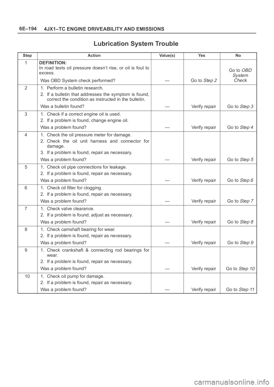
Lubrication System Trouble
StepActionVa l u e ( s )Ye sNo
1DEFINITION:
In road tests oil pressure doesn’t rise, or oil is foul to
excess.
Was OBD System check performed?
—Go to Step 2
Go to OBD
System
Check
21. Perform a bulletin research.
2. If a bulletin that addresses the symptom is found,
correct the condition as instructed in the bulletin.
Was a bulletin found?
—Verify repairGo to Step 3
31. Check if a correct engine oil is used.
2. If a problem is found, change engine oil.
Was a problem found?
—Verify repairGo to Step 4
41. Check the oil pressure meter for damage.
2. Check the oil unit harness and connector for
damage.
3. If a problem is found, repair as necessary.
Was a problem found?
—Verify repairGo to Step 5
51. Check oil pipe connections for leakage.
2. If a problem is found, repair as necessary.
Was a problem found?
—Verify repairGo to Step 6
61. Check oil filter for clogging.
2. If a problem is found, repair as necessary.
Was a problem found?
—Verify repairGo to Step 7
71. Check valve clearance.
2. If a problem is found, adjust as necessary.
Was a problem found?
—Verify repairGo to Step 8
81. Check camshaft bearing for wear.
2. If a problem is found, repair as necessary.
Was a problem found?
—Verify repairGo to Step 9
91. Check crankshaft & connecting rod bearings for
wear.
2. If a problem is found, repair as necessary.
Was a problem found?
—Verify repairGo to Step 10
101. Check oil pump for damage.
2. If a problem is found, repair as necessary.
Was a problem found?
—Verify repairGo to Step 11
Page 5627 of 6000
6E–198
4JX1–TC ENGINE DRIVEABILITY AND EMISSIONS
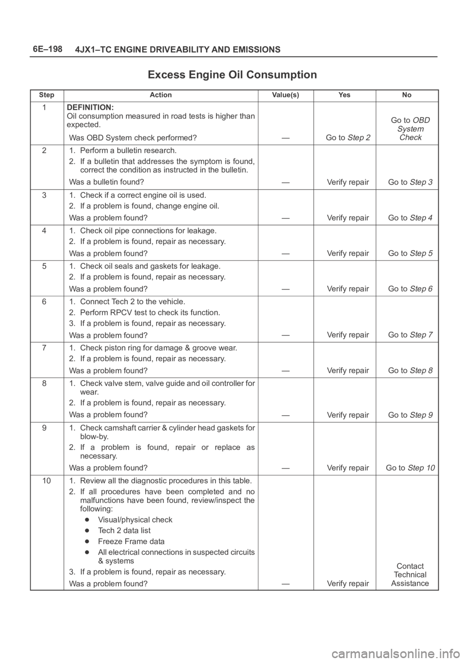
Excess Engine Oil Consumption
StepActionVa l u e ( s )Ye sNo
1DEFINITION:
Oil consumption measured in road tests is higher than
expected.
Was OBD System check performed?
—Go to Step 2
Go to OBD
System
Check
21. Perform a bulletin research.
2. If a bulletin that addresses the symptom is found,
correct the condition as instructed in the bulletin.
Was a bulletin found?
—Verify repairGo to Step 3
31. Check if a correct engine oil is used.
2. If a problem is found, change engine oil.
Was a problem found?
—Verify repairGo to Step 4
41. Check oil pipe connections for leakage.
2. If a problem is found, repair as necessary.
Was a problem found?
—Verify repairGo to Step 5
51. Check oil seals and gaskets for leakage.
2. If a problem is found, repair as necessary.
Was a problem found?
—Verify repairGo to Step 6
61. Connect Tech 2 to the vehicle.
2. Perform RPCV test to check its function.
3. If a problem is found, repair as necessary.
Was a problem found?
—Verify repairGo to Step 7
71. Check piston ring for damage & groove wear.
2. If a problem is found, repair as necessary.
Was a problem found?
—Verify repairGo to Step 8
81. Check valve stem, valve guide and oil controller for
wear.
2. If a problem is found, repair as necessary.
Was a problem found?
—Verify repairGo to Step 9
91. Check camshaft carrier & cylinder head gaskets for
blow-by.
2. If a problem is found, repair or replace as
necessary.
Was a problem found?
—Verify repairGo to Step 10
101. Review all the diagnostic procedures in this table.
2. If all procedures have been completed and no
malfunctions have been found, review/inspect the
following:
Visual/physical check
Tech 2 data list
Freeze Frame data
All electrical connections in suspected circuits
& systems
3. If a problem is found, repair as necessary.
Was a problem found?
—Verify repair
Contact
Te c h n i c a l
Assistance
Page 5639 of 6000
6E–210
4JX1–TC ENGINE DRIVEABILITY AND EMISSIONS
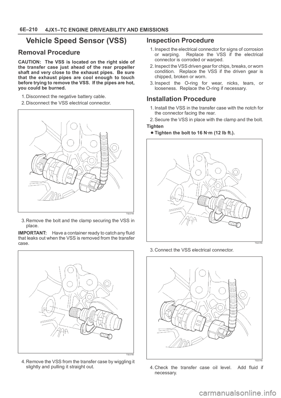
Vehicle Speed Sensor (VSS)
Removal Procedure
CAUTION: The VSS is located on the right side of
the transfer case just ahead of the rear propeller
shaft and very close to the exhaust pipes. Be sure
that the exhaust pipes are cool enough to touch
before trying to remove the VSS. If the pipes are hot,
you could be burned.
1. Disconnect the negative battery cable.
2. Disconnect the VSS electrical connector.
TS23748
3. Remove the bolt and the clamp securing the VSS in
place.
IMPORTANT:H a v e a c o n t a i n e r r e a d y t o c a t c h a n y f l u i d
that leaks out when the VSS is removed from the transfer
case.
TS23780
4. Remove the VSS from the transfer case by wiggling it
slightly and pulling it straight out.
Inspection Procedure
1. Inspect the electrical connector for signs of corrosion
or warping. Replace the VSS if the electrical
connector is corroded or warped.
2. Inspect the VSS driven gear for chips, breaks, or worn
condition. Replace the VSS if the driven gear is
chipped, broken or worn.
3. Inspect the O-ring for wear, nicks, tears, or
looseness. Replace the O-ring if necessary.
Installation Procedure
1. Install the VSS in the transfer case with the notch for
the connector facing the rear.
2. Secure the VSS in place with the clamp and the bolt.
Tighten
Tighten the bolt to 16 Nꞏm (12 lb ft.).
TS23780
3. Connect the VSS electrical connector.
TS23748
4. Check the transfer case oil level. Add fluid if
necessary.