1998 OPEL FRONTERA check oil
[x] Cancel search: check oilPage 5275 of 6000
6A – 2 ENGINE MECHANICAL
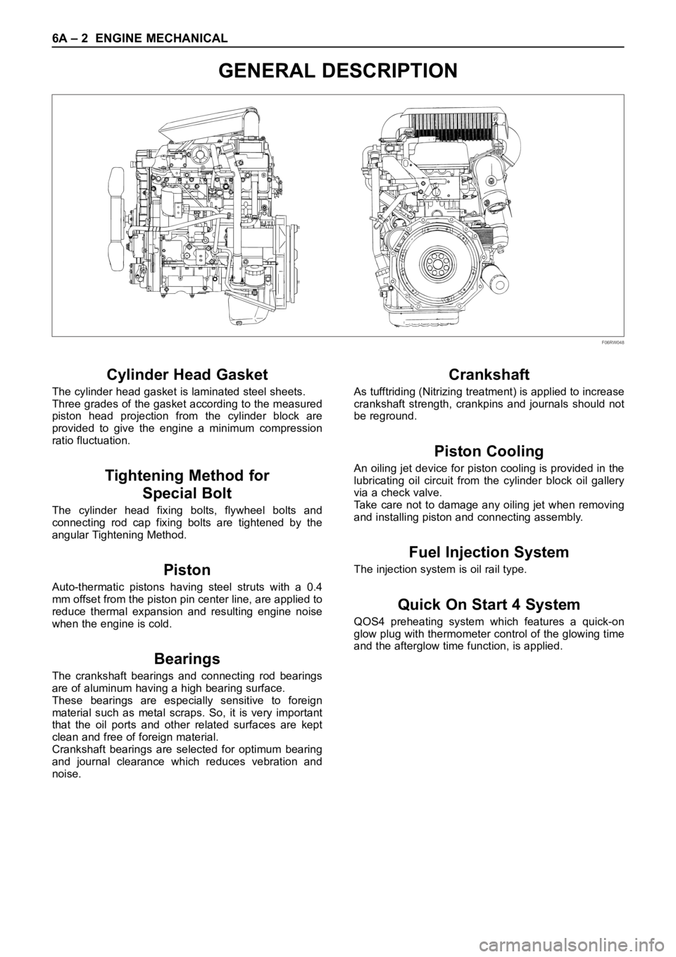
GENERAL DESCRIPTION
Cylinder Head Gasket
The cylinder head gasket is laminated steel sheets.
Three grades of the gasket according to the measured
piston head projection from the cylinder block are
provided to give the engine a minimum compression
ratio fluctuation.
Tightening Method for
Special Bolt
The cylinder head fixing bolts, flywheel bolts and
connecting rod cap fixing bolts are tightened by the
angular Tightening Method.
Piston
Auto-thermatic pistons having steel struts with a 0.4
mm offset from the piston pin center line, are applied to
reduce thermal expansion and resulting engine noise
when the engine is cold.
Bearings
The crankshaft bearings and connecting rod bearings
are of aluminum having a high bearing surface.
These bearings are especially sensitive to foreign
material such as metal scraps. So, it is very important
that the oil ports and other related surfaces are kept
clean and free of foreign material.
Crankshaft bearings are selected for optimum bearing
and journal clearance which reduces vebration and
noise.
Crankshaft
As tufftriding (Nitrizing treatment) is applied to increase
crankshaft strength, crankpins and journals should not
be reground.
Piston Cooling
An oiling jet device for piston cooling is provided in the
lubricating oil circuit from the cylinder block oil gallery
via a check valve.
Take care not to damage any oiling jet when removing
and installing piston and connecting assembly.
Fuel Injection System
The injection system is oil rail type.
Quick On Start 4 System
QOS4 preheating system which features a quick-on
glow plug with thermometer control of the glowing time
and the afterglow time function, is applied.
F06RW048
Page 5283 of 6000
6A – 10 ENGINE MECHANICAL
8. Check the engine oil level and replenish to the
specified level if required.
9. Start the engine and check for oil leakage from the
main oil filter.
FUEL SYSTEM
Fuel filter
Replacement Procedure
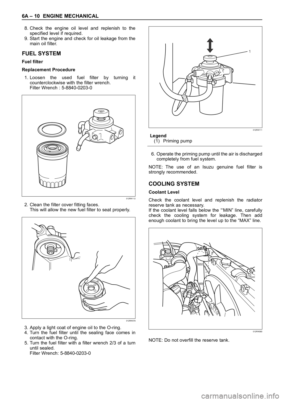
1. Loosen the used fuel filter by turning it
counterclockwise with the filter wrench.
Filter Wrench : 5-8840-0203-0
2. Clean the filter cover fitting faces.
This will allow the new fuel filter to seat properly.
3. Apply a light coat of engine oil to the O-ring.
4. Turn the fuel filter until the sealing face comes in
contact with the O-ring.
5. Turn the fuel filter with a filter wrench 2/3 of a turn
until sealed.
Filter Wrench: 5-8840-0203-0Legend
(1) Priming pump
6. Operate the priming pump until the air is discharged
completely from fuel system.
NOTE: The use of an Isuzu genuine fuel filter is
strongly recommended.
COOLING SYSTEM
Coolant Level
Check the coolant level and replenish the radiator
reserve tank as necessary.
If the coolant level falls below the “‘MIN” line, carefully
check the cooling system for leakage. Then add
enough coolant to bring the level up to the “MAX” line.
NOTE: Do not overfill the reserve tank.
012RW112
012RW078
1
012RW111
012RW080
Page 5291 of 6000
6A – 18 ENGINE MECHANICAL
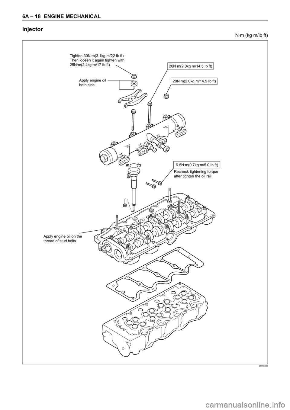
Injector
Nꞏm (kgꞏm/lbꞏft)
011RX003
20Nꞏm(2.0kgꞏm/14.5 Ib ft)
6.5Nꞏm(0.7kgꞏm/5.0 Ib ft)
Recheck tightening torque
after tighten the oil rail
Apply engine oil on the
thread of stud bolts
20Nꞏm(2.0kgꞏm/14.5 Ib ft)
Tighten 30Nꞏm(3.1kgꞏm/22 Ib ft)
Then loosen it again tighten with
25Nꞏm(2.4kgꞏm/17 Ib ft)
Apply engine oil
both side
Page 5332 of 6000
ENGINE MECHANICAL 6A – 59
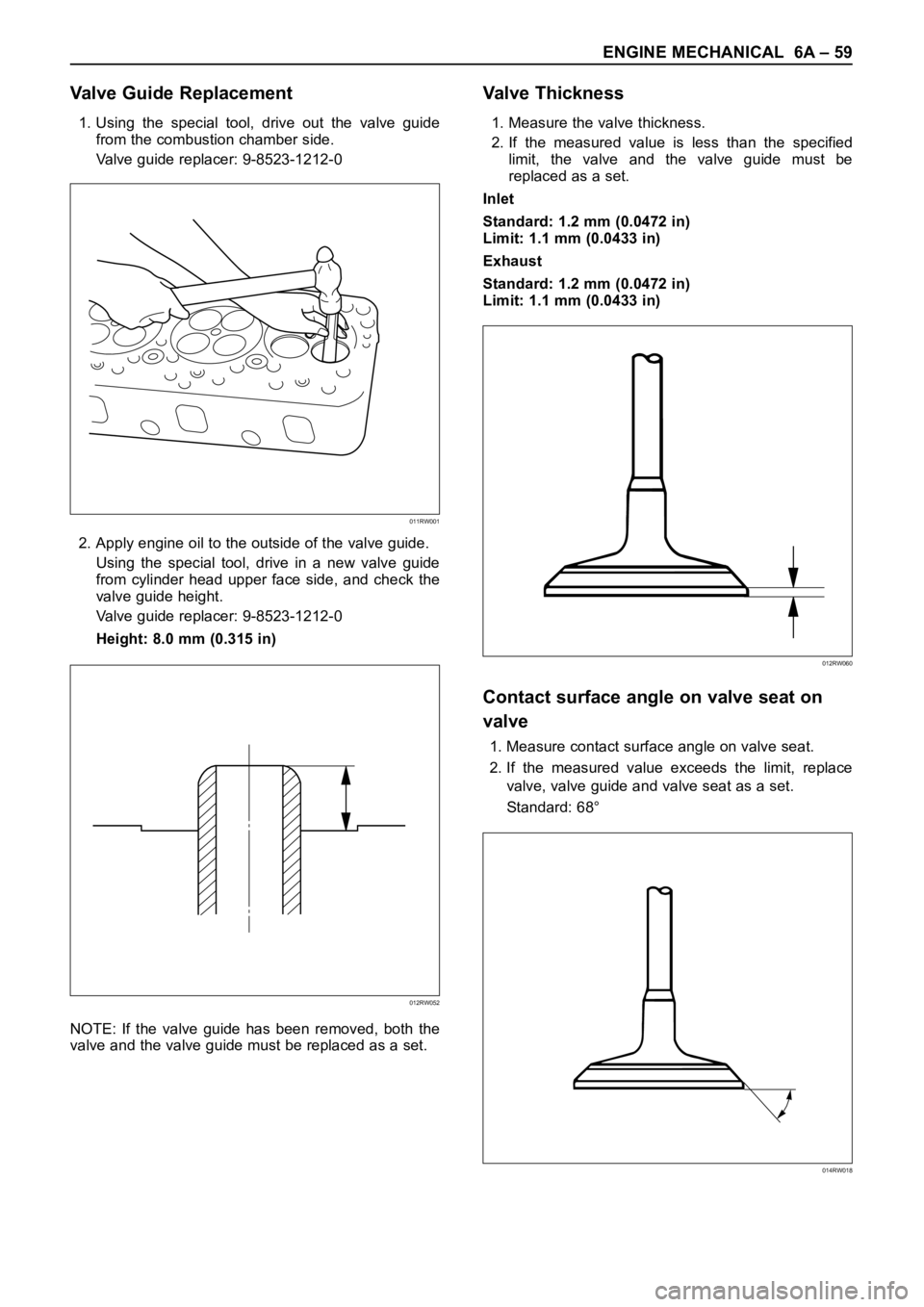
Valve Guide Replacement
1. Using the special tool, drive out the valve guide
from the combustion chamber side.
Valve guide replacer: 9-8523-1212-0
2. Apply engine oil to the outside of the valve guide.
Using the special tool, drive in a new valve guide
from cylinder head upper face side, and check the
valve guide height.
Valve guide replacer: 9-8523-1212-0
Height: 8.0 mm (0.315 in)
NOTE: If the valve guide has been removed, both the
valve and the valve guide must be replaced as a set.
Valve Thickness
1. Measure the valve thickness.
2. If the measured value is less than the specified
limit, the valve and the valve guide must be
replaced as a set.
Inlet
Standard: 1.2 mm (0.0472 in)
Limit: 1.1 mm (0.0433 in)
Exhaust
Standard: 1.2 mm (0.0472 in)
Limit: 1.1 mm (0.0433 in)
Contact surface angle on valve seat on
valve
1. Measure contact surface angle on valve seat.
2. If the measured value exceeds the limit, replace
valve, valve guide and valve seat as a set.
Standard: 68°
011RW001
012RW052
012RW060
014RW018
Page 5336 of 6000
ENGINE MECHANICAL 6A – 63
VALVE CLEARANCE ADJUSTMENT
NOTE:
1. Valve clearance should be inspected and adjusted
while the engine is cool.
2. The tightening of the camshaft bearing cap and
camshaft carrier assembly should be checked
before inspecting and adjusting valve clearance.
INSPECTION
1. Remove cylinder head noise insulator cover and
cylinder head cover.
Refer to “Cylinder Head” in this manual.
2. Disconnect all harness connecters of the injector
and remove harness assembly.
3. Drain oil from oil rail assembly.
4. Remove injector clamp nuts and fixing bolts to take
out injector assembly.
5. Loosen oil rail bolts, remove oil rail assembly.
6. Set cylinder No.1 to the TDC at the compression
stroke. Make sure that there is play in cylinder No.1
tappets on inlet and exhaust sides and that there is
no play in cylinder No.4 tappets.
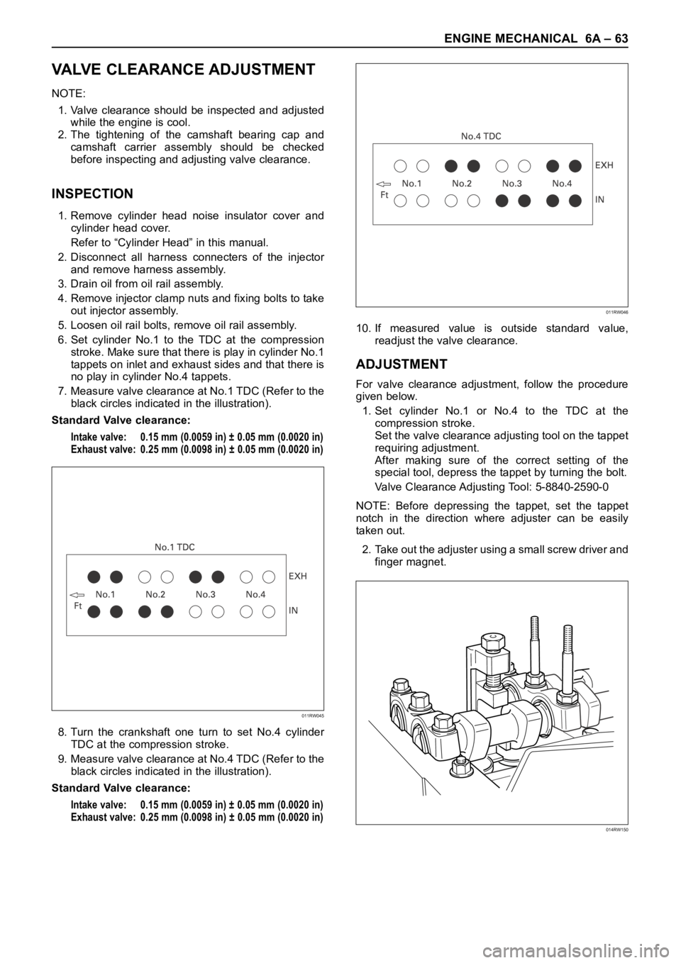
7. Measure valve clearance at No.1 TDC (Refer to the
black circles indicated in the illustration).
Standard Valve clearance:
Intake valve: 0.15 mm (0.0059 in) ± 0.05 mm (0.0020 in)
Exhaust valve: 0.25 mm (0.0098 in) ± 0.05 mm (0.0020 in)
8. Turn the crankshaft one turn to set No.4 cylinder
TDC at the compression stroke.
9. Measure valve clearance at No.4 TDC (Refer to the
black circles indicated in the illustration).
Standard Valve clearance:
Intake valve: 0.15 mm (0.0059 in) ± 0.05 mm (0.0020 in)
Exhaust valve: 0.25 mm (0.0098 in) ± 0.05 mm (0.0020 in)
10. If measured value is outside standard value,
readjust the valve clearance.
ADJUSTMENT
For valve clearance adjustment, follow the procedure
given below.
1. Set cylinder No.1 or No.4 to the TDC at the
compression stroke.
Set the valve clearance adjusting tool on the tappet
requiring adjustment.
After making sure of the correct setting of the
special tool, depress the tappet by turning the bolt.
Valve Clearance Adjusting Tool: 5-8840-2590-0
NOTE: Before depressing the tappet, set the tappet
notch in the direction where adjuster can be easily
taken out.
2. Take out the adjuster using a small screw driver and
finger magnet.
011RW045
011RW046
014RW150
Page 5344 of 6000
ENGINE MECHANICAL 6A – 71
DISASSEMBLY
1. Cylinder Head
1) Refer to “Cylinder head” in this manual.
2. Crankshaft Front Oil Seal
1) Use a plastic hammer and a screwdriver to tap
around the oil seal to free it from the gear case
cover.
Take care not to damage the oil seal fitting
surfaces.
3. Crankshaft Timing Gear
4. Timing Gear Case
5. Flywheel
6. Cylinder Block Rear Plate
7. Crankshaft Rear Oil Seal
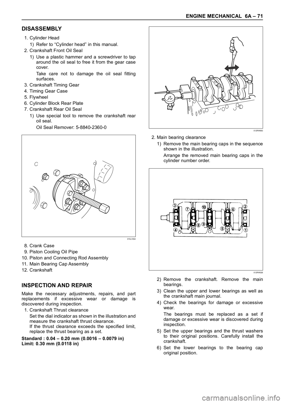
1) Use special tool to remove the crankshaft rear
oil seal.
Oil Seal Remover: 5-8840-2360-0
8. Crank Case
9. Piston Cooling Oil Pipe
10. Piston and Connecting Rod Assembly
11. Main Bearing Cap Assembly
12. Crankshaft
INSPECTION AND REPAIR
Make the necessary adjustments, repairs, and part
replacements if excessive wear or damage is
discovered during inspection.
1. Crankshaft Thrust clearance
Set the dial indicator as shown in the illustration and
measure the crankshaft thrust clearance.
If the thrust clearance exceeds the specified limit,
replace the thrust bearing as a set.
Standard : 0.04 – 0.20 mm (0.0016 – 0.0079 in)
Limit: 0.30 mm (0.0118 in)2. Main bearing clearance
1) Remove the main bearing caps in the sequence
shown in the illustration.
Arrange the removed main bearing caps in the
cylinder number order.
2) Remove the crankshaft. Remove the main
bearings.
3) Clean the upper and lower bearings as well as
the crankshaft main journal.
4) Check the bearings for damage or excessive
wear.
The bearings must be replaced as a set if
damage or excessive wear is discovered during
inspection.
5) Set the upper bearings and the thrust washers
to their original positions. Carefully install the
crankshaft.
6) Set the lower bearings to the bearing cap
original position.
015LV002
012RW063
371062
51
984
012RW026
Page 5348 of 6000
ENGINE MECHANICAL 6A – 75
Main Bearing Crankshaft
Bore Diameter mm(in) Main Journal Diameter mm(in)Crankshaft Oil Clearance
Grade Inside Diameter Grade Outside DiameterBearing mm(in)
1 or - 69.927 – 69.932 4 0.045 – 0.061
(2.7530 – 2.7532) (0.0018 – 0.0024)
1 73.992 – 74.000 2 or - - 69.922 – 69.927 4 0.050 – 0.066
(2.9131 – 2.9134) (2.7528 – 2.7530) (0.0020 – 0.0026)
3 or - - - 69.917 – 69.922 5 0.052 – 0.068
(2.7526 – 2.7528) (0.0020 – 0.0027)
1 or - 69.927 – 69.932 2 0.042 – 0.059
(2.7530 – 2.7532) (0.0017 – 0.0023)
2 73.983 – 73.992 2 or - - 69.922 – 69.927 3 0.044 – 0.061
(2.9127 – 2.9131) (2.7528 – 2.7530) (0.0017 – 0.0024)
3 or - - - 69.917 – 69.922 4 0.046 – 0.063
(2.7526 – 2.7528) (0.0018 – 0.0025)
1 or - 69.927 – 69.932 1 0.037 – 0.053
(2.7530 – 2.7532) (0.0015 – 0.0021)
3 73.975 – 73.983 2 or - - 69.922 – 69.927 2 0.039 – 0.055
(2.9124 – 2.9127) (2.7528 – 2.7530) (0.0015 – 0.0022)
3 or - - - 69.917 – 69.922 2 0.044 – 0.060
(2.7526 – 2.7528) (0.0017 – 0.0024)
REASSEMBLY
1. Crankshaft
1) Install the main bearings to the cylinder body
and the main bearing caps.
2) Be sure that they are positioned correctly.
3) Apply new engine oil to the upper and lower
main bearing faces.
4) Carefully mount the crankshaft.
5) Apply engine oil to the thrust washer.
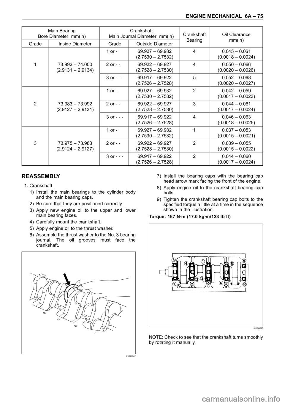
6) Assemble the thrust washer to the No. 3 bearing
journal. The oil grooves must face the
crankshaft.7) Install the bearing caps with the bearing cap
head arrow mark facing the front of the engine.
8) Apply engine oil to the crankshaft bearing cap
bolts.
9) Tighten the crankshaft bearing cap bolts to the
specified torque a little at a time in the sequence
shown in the illustration.
Torque: 167 Nꞏm (17.0 kgꞏm/123 lb ft)
NOTE: Check to see that the crankshaft turns smoothly
by rotating it manually.
012RW047
84159
610
237
012RW027
Page 5349 of 6000
6A – 76 ENGINE MECHANICAL
3. Piston and Connecting Rod Assembly
1) Apply engine oil to the cylinder bores, the
connecting rod bearings and the crankshaft pins
and each piston ring and piston.
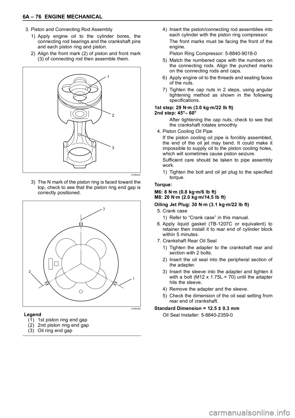
2) Align the front mark (2) of piston and front mark
(3) of connecting rod then assemble them.
3) The N mark of the piston ring is faced toward the
top, check to see that the piston ring end gap is
correctly positioned.
Legend
(1) 1st piston ring end gap
(2) 2nd piston ring end gap
(3) Oil ring end gap4) Insert the piston/connecting rod assemblies into
each cylinder with the piston ring compressor.
The front marks must be facing the front of the
engine.
Piston Ring Compressor: 5-8840-9018-0
5) Match the numbered caps with the numbers on
the connecting rods. Align the punched marks
on the connecting rods and caps.
6) Apply engine oil to the threads and seating faces
of the nuts.
7) Tighten the cap nuts in 2 steps, using angular
tightening method as shown in the following
specifications.
1st step: 29 Nꞏm (3.0 kgꞏm/22 lb ft)
2nd step: 45°– 60°
After tightening the cap nuts, check to see that
the crankshaft rotates smoothly
4. Piston Cooling Oil Pipe
If the piston cooling oil pipe is forcibly assembled,
the end of the oil jet may bend. It could make it
impossible to supply oil to the piston cooling holes,
which will sometimes cause piston seizure.
Sufficient care should be taken to pipe assembly
work.
1) Tighten the bolt and oil jet plug to the specified
torque.
To r q u e :
M6: 8 Nꞏm (0.8 kgꞏm/6 lb ft)
M8: 20 Nꞏm (2.0 kgꞏm/14.5 lb ft)
Oiling Jet Plug: 30 Nꞏm (3.1 kgꞏm/22 lb ft)
5. Crank case
1) Refer to “Crank case” in this manual.
6. Apply liquid gasket (TB-1207C or equivalent) to
retainer then install it to rear end of cylinder block
within 5 minutes.
7. Crankshaft Rear Oil Seal
1) Tighten the adapter to the crankshaft rear and
section with 2 bolts.
2) Insert the oil seal into the peripheral section of
the adapter.
3) Insert the sleeve into the adapter and tighten it
with a bolt (M12 x 1.75L = 70) until the adapter
hits the sleeve.
4) Remove the adapter and the sleeve.
5) Check the dimension of the oil seal setting from
rear end of crankshaft.
Standard Dimension = 12.5 ± 0.3 mm
Oil Seal Installer: 5-8840-2359-0
2
3
1
015RW051
3
1
2
015RW083