1998 OPEL FRONTERA battery
[x] Cancel search: batteryPage 2195 of 6000
7A–41 AUTOMATIC TRANSMISSION (4L30–E)
Speed Sensor (Extension Housing)
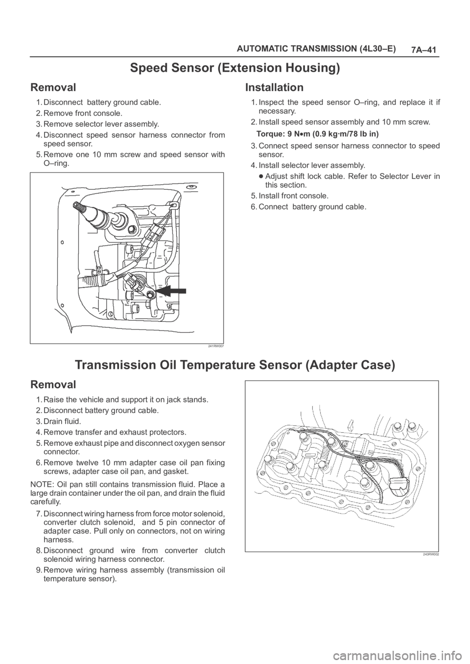
Removal
1. Disconnect battery ground cable.
2. Remove front console.
3. Remove selector lever assembly.
4. Disconnect speed sensor harness connector from
speed sensor.
5. Remove one 10 mm screw and speed sensor with
O–ring.
241RW007
Installation
1. Inspect the speed sensor O–ring, and replace it if
necessary.
2. Install speed sensor assembly and 10 mm screw.
To r q u e : 9 N
m (0.9 kgꞏm/78 lb in)
3. Connect speed sensor harness connector to speed
sensor.
4. Install selector lever assembly.
Adjust shift lock cable. Refer to Selector Lever in
this section.
5. Install front console.
6. Connect battery ground cable.
Transmission Oil Temperature Sensor (Adapter Case)
Removal
1. Raise the vehicle and support it on jack stands.
2. Disconnect battery ground cable.
3. Drain fluid.
4. Remove transfer and exhaust protectors.
5. Remove exhaust pipe and disconnect oxygen sensor
connector.
6. Remove twelve 10 mm adapter case oil pan fixing
screws, adapter case oil pan, and gasket.
NOTE: Oil pan still contains transmission fluid. Place a
large drain container under the oil pan, and drain the fluid
carefully.
7. Disconnect wiring harness from force motor solenoid,
converter clutch solenoid, and 5 pin connector of
adapter case. Pull only on connectors, not on wiring
harness.
8. Disconnect ground wire from converter clutch
solenoid wiring harness connector.
9. Remove wiring harness assembly (transmission oil
temperature sensor).
243RW002
Page 2196 of 6000
7A–42
AUTOMATIC TRANSMISSION (4L30–E)
Installation
1. Connect ground wire to converter clutch solenoid
wiring harness connector of the wiring harness
assembly.
2. Install wiring harness assembly to converter clutch
solenoid, force motor, and 5 pin connector of adapter
case.
3. Install oil pan gasket, oil pan, and twelve 10 mm fixing
screws. Tighten the screws to the specified torque.
Torque: 11 N
m (1.1 kgꞏm/96 lb in)4. Install exhaust pipe and connect oxygen sensor
connector. Tighten the bolts to the specified torque.
Exhaust pipe flange bolt torque:
43 N
m(4.4kgꞏm/32lbft)
5. Install transfer and exhaust protectors. Tighten the
bolts to the specified torque.
To r q u e : 3 7 N
m (3.8 kgꞏm/27 lb ft)
6. Fill transmission through the overfill screw hole of oil
pan, using ATF DEXRON
–III.
Refer to Changing Transmission Fluid in this section.
7. Connect battery ground cable.
Front Oil Seal (Converter Housing)
Removal
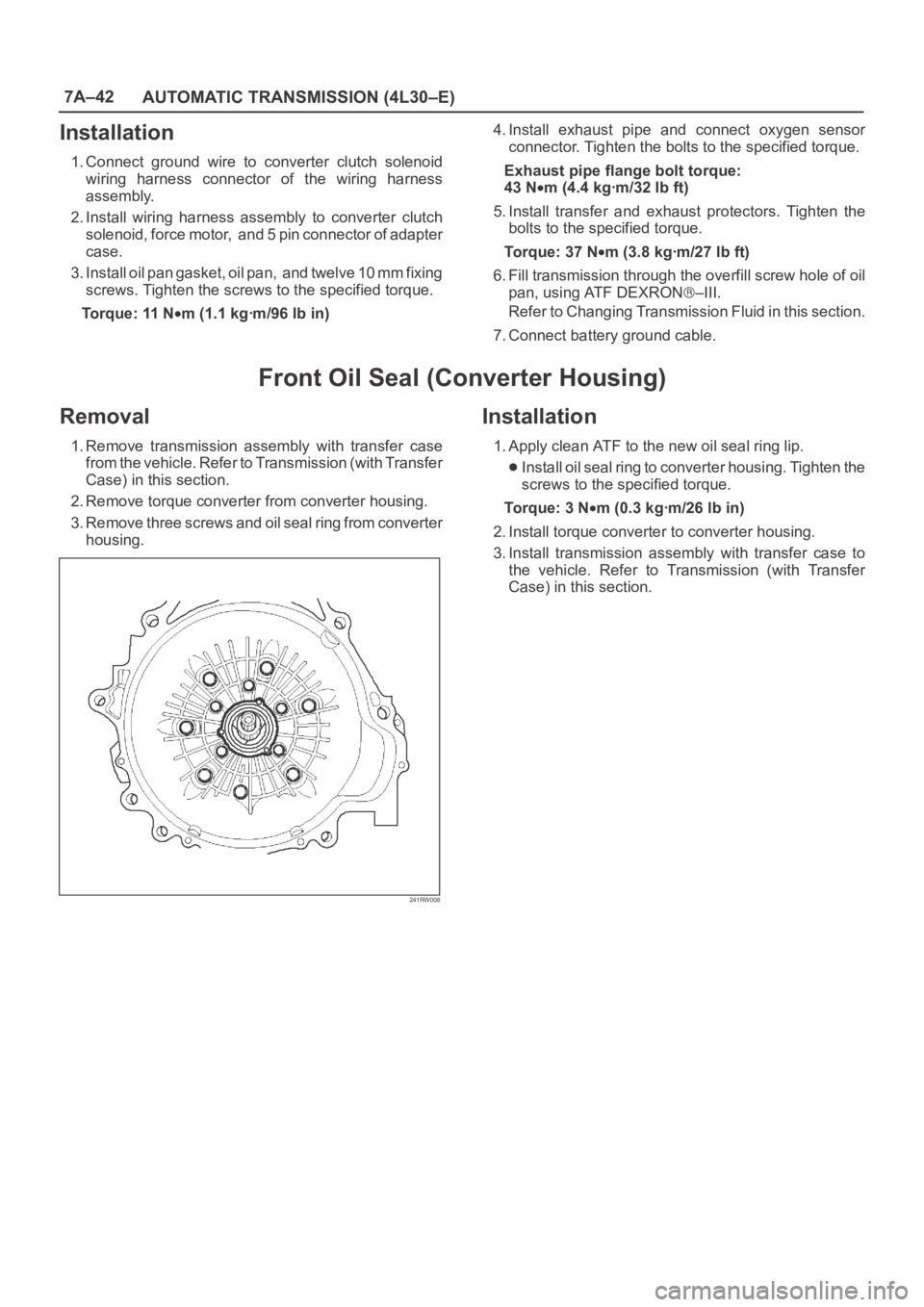
1. Remove transmission assembly with transfer case
from the vehicle. Refer to Transmission (with Transfer
Case) in this section.
2. Remove torque converter from converter housing.
3. Remove three screws and oil seal ring from converter
housing.
241RW008
Installation
1. Apply clean ATF to the new oil seal ring lip.
Install oil seal ring to converter housing. Tighten the
screws to the specified torque.
To r q u e : 3 N
m (0.3 kgꞏm/26 lb in)
2. Install torque converter to converter housing.
3. Install transmission assembly with transfer case to
the vehicle. Refer to Transmission (with Transfer
Case) in this section.
Page 2257 of 6000
7A1–12
TRANSMISSION CONTROL SYSTEM (4L30–E)
“Check Trans” Check
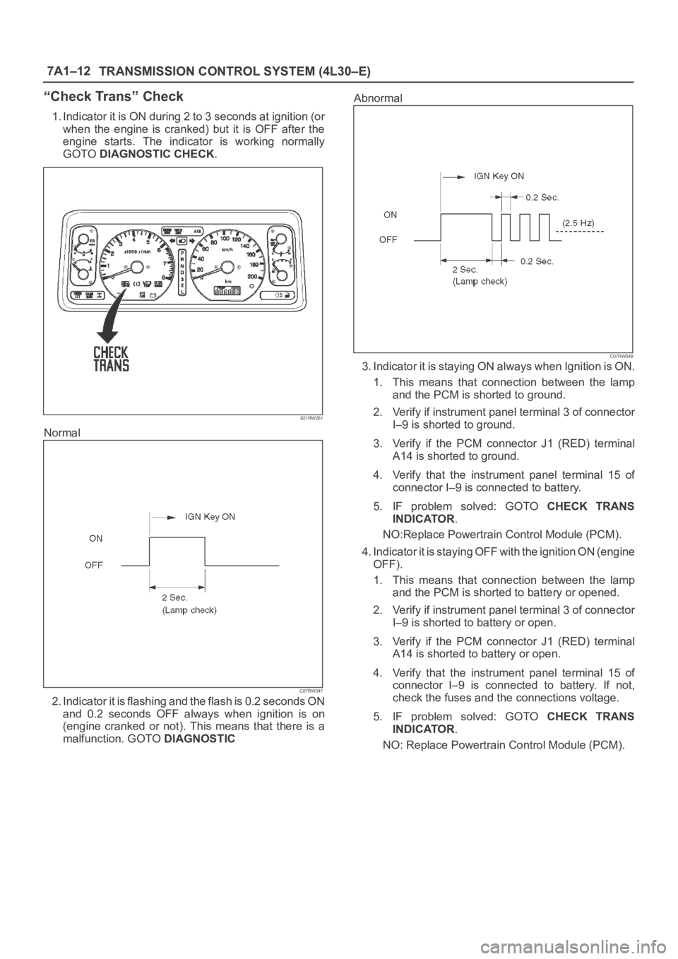
1. Indicator it is ON during 2 to 3 seconds at ignition (or
when the engine is cranked) but it is OFF after the
engine starts. The indicator is working normally
GOTO DIAGNOSTIC CHECK.
821RW261
Normal
C07RW047
2. Indicator it is flashing and the flash is 0.2 seconds ON
and 0.2 seconds OFF always when ignition is on
(engine cranked or not). This means that there is a
malfunction. GOTO DIAGNOSTICAbnormal
C07RW048
3. Indicator it is staying ON always when Ignition is ON.
1. This means that connection between the lamp
and the PCM is shorted to ground.
2. Verify if instrument panel terminal 3 of connector
I–9 is shorted to ground.
3. Verify if the PCM connector J1 (RED) terminal
A14 is shorted to ground.
4. Verify that the instrument panel terminal 15 of
connector I–9 is connected to battery.
5. IF problem solved: GOTO CHECK TRANS
INDICATOR.
NO:Replace Powertrain Control Module (PCM).
4. Indicator it is staying OFF with the ignition ON (engine
OFF).
1. This means that connection between the lamp
and the PCM is shorted to battery or opened.
2. Verify if instrument panel terminal 3 of connector
I–9 is shorted to battery or open.
3. Verify if the PCM connector J1 (RED) terminal
A14 is shorted to battery or open.
4. Verify that the instrument panel terminal 15 of
connector I–9 is connected to battery. If not,
check the fuses and the connections voltage.
5. IF problem solved: GOTO CHECK TRANS
INDICATOR.
NO: Replace Powertrain Control Module (PCM).
Page 2265 of 6000
7A1–20
TRANSMISSION CONTROL SYSTEM (4L30–E)
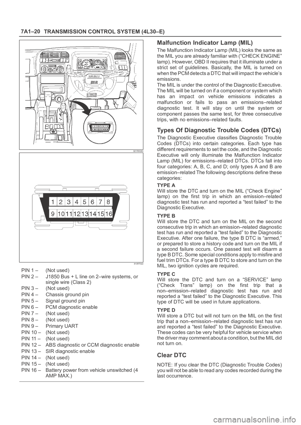
821RW263
810RT022
PIN 1 – (Not used)
PIN 2 – J1850 Bus + L line on 2–wire systems, or
single wire (Class 2)
PIN 3 – (Not used)
PIN 4 – Chassis ground pin
PIN 5 – Signal ground pin
PIN 6 – PCM diagnostic enable
PIN 7 – (Not used)
PIN 8 – (Not used)
PIN 9 – Primary UART
PIN 10 – (Not used)
PIN 11 – (Not used)
PIN 12 – ABS diagnostic or CCM diagnostic enable
PIN 13 – SIR diagnostic enable
PIN 14 – (Not used)
PIN 15 – (Not used)
PIN 16 – Battery power from vehicle unswitched (4
AMP MAX.)
Malfunction Indicator Lamp (MIL)
The Malfunction Indicator Lamp (MIL) looks the same as
the MIL you are already familiar with (“CHECK ENGINE”
lamp). However, OBD II requires that it illuminate under a
strict set of guidelines. Basically, the MIL is turned on
when the PCM detects a DTC that will impact the vehicle’s
emissions.
The MIL is under the control of the Diagnostic Executive.
The MIL will be turned on if a component or system which
has an impact on vehicle emissions indicates a
malfunction or fails to pass an emissions–related
diagnostic test. It will stay on until the system or
component passes the same test, for three consecutive
trips, with no emissions–related faults.
Types Of Diagnostic Trouble Codes (DTCs)
The Diagnostic Executive classifies Diagnostic Trouble
Codes (DTCs) into certain categories. Each type has
different requirements to set the code, and the Diagnostic
Executive will only illuminate the Malfunction Indicator
Lamp (MIL) for emissions–related DTCs. DTCs fall into
four categories: A, B, C, and D; only types A and B are
emission–related The following descriptions define these
categories:
TYPE A
Will store the DTC and turn on the MIL (“Check Engine”
lamp) on the first trip in which an emission–related
diagnostic test has run and reported a “test failed” to the
Diagnostic Executive.
TYPE B
Will store the DTC and turn on the MIL on the second
consecutive trip in which an emission–related diagnostic
test has run and reported a “test failed” to the Diagnostic
Executive. After one failure, the type B DTC is “armed,”
or prepared to store a history code and turn on the MIL if
a second failure occurs. One passed test will disarm a
type B DTC. Some special conditions apply to misfire and
fuel trim DTCs. For a type B DTC to store and turn on the
MIL, two ignition cycles are required.
TYPE C
Will store the DTC and turn on a “SERVICE” lamp
(“Check Trans” lamp) on the first trip that a
non–emission–related diagnostic test has run and
reported a “test failed” to the Diagnostic Executive. This
type of DTC will be used in future applications.
TYPE D
Will store a DTC but will not turn on the MIL on the first
trip that a non–emission–related diagnostic test has run
and reported a “test failed” to the Diagnostic Executive.
These codes can be very helpful for vehicle service when
the driver may comment about a condition, but the MIL did
not turn on.
Clear DTC
NOTE: If you clear the DTC (Diagnostic Trouble Codes)
you will not be able to read any codes recorded during the
last occurrence.
Page 2272 of 6000
TRANSMISSION CONTROL SYSTEM (4L30–E)7A1–27
DTC P0560 System Voltage Malfunction
D07RW030
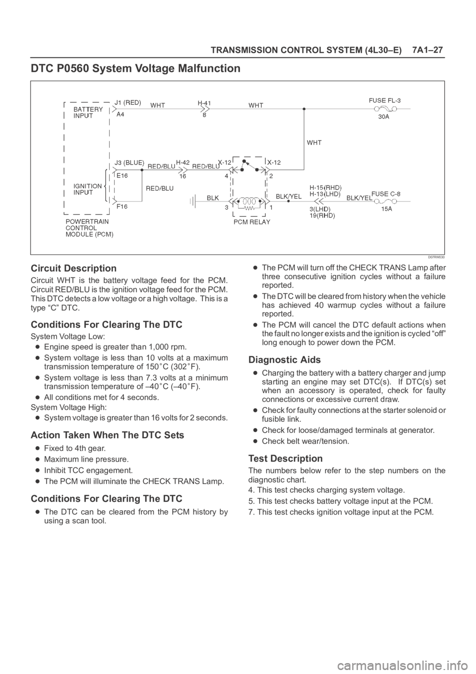
Circuit Description
Circuit WHT is the battery voltage feed for the PCM.
Circuit RED/BLU is the ignition voltage feed for the PCM.
This DTC detects a low voltage or a high voltage. This is a
type “C” DTC.
Conditions For Clearing The DTC
System Voltage Low:
Engine speed is greater than 1,000 rpm.
System voltage is less than 10 volts at a maximum
transmission temperature of 150
C (302F).
System voltage is less than 7.3 volts at a minimum
transmission temperature of –40
C (–40F).
All conditions met for 4 seconds.
System Voltage High:
System voltage is greater than 16 volts for 2 seconds.
Action Taken When The DTC Sets
Fixed to 4th gear.
Maximum line pressure.
Inhibit TCC engagement.
The PCM will illuminate the CHECK TRANS Lamp.
Conditions For Clearing The DTC
The DTC can be cleared from the PCM history by
using a scan tool.
The PCM will turn off the CHECK TRANS Lamp after
three consecutive ignition cycles without a failure
reported.
The DTC will be cleared from history when the vehicle
has achieved 40 warmup cycles without a failure
reported.
The PCM will cancel the DTC default actions when
the fault no longer exists and the ignition is cycled “off”
long enough to power down the PCM.
Diagnostic Aids
Charging the battery with a battery charger and jump
starting an engine may set DTC(s). If DTC(s) set
when an accessory is operated, check for faulty
connections or excessive current draw.
Check for faulty connections at the starter solenoid or
fusible link.
Check for loose/damaged terminals at generator.
Check belt wear/tension.
Test Description
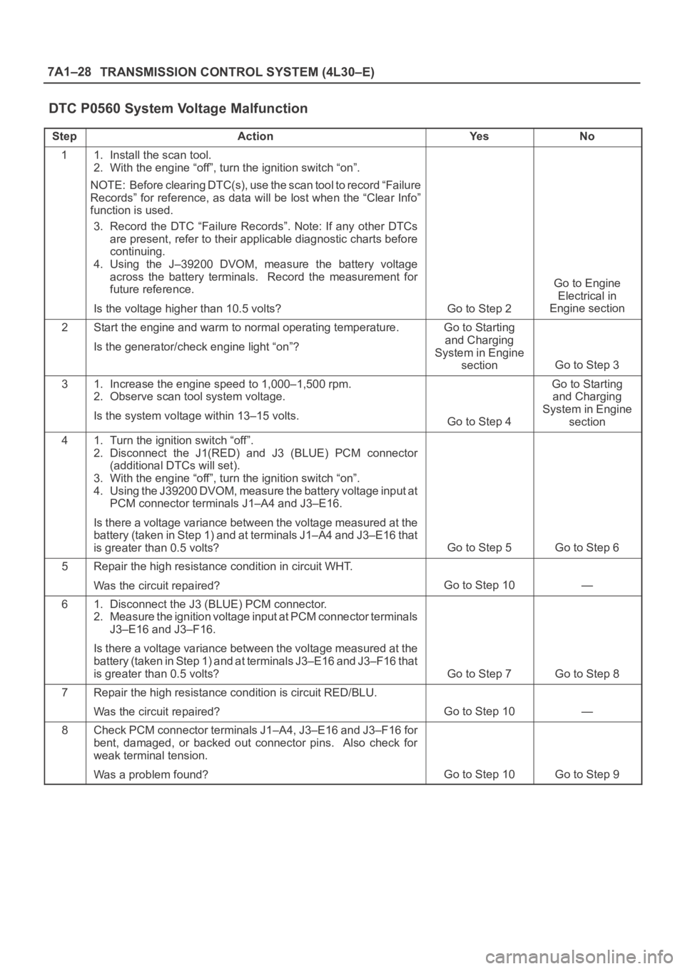
The numbers below refer to the step numbers on the
diagnostic chart.
4. This test checks charging system voltage.
5. This test checks battery voltage input at the PCM.
7. This test checks ignition voltage input at the PCM.
Page 2273 of 6000
7A1–28
TRANSMISSION CONTROL SYSTEM (4L30–E)
DTC P0560 System Voltage Malfunction
StepActionYe sNo
11. Install the scan tool.
2. With the engine “off”, turn the ignition switch “on”.
NOTE: Before clearing DTC(s), use the scan tool to record “Failure
Records” for reference, as data will be lost when the “Clear Info”
function is used.
3. Record the DTC “Failure Records”. Note: If any other DTCs
are present, refer to their applicable diagnostic charts before
continuing.
4. Using the J–39200 DVOM, measure the battery voltage
across the battery terminals. Record the measurement for
future reference.
Is the voltage higher than 10.5 volts?
Go to Step 2
Go to Engine
Electrical in
Engine section
2Start the engine and warm to normal operating temperature.
Is the generator/check engine light “on”?Go to Starting
and Charging
System in Engine
section
Go to Step 3
31. Increase the engine speed to 1,000–1,500 rpm.
2. Observe scan tool system voltage.
Is the system voltage within 13–15 volts.
Go to Step 4
Go to Starting
and Charging
System in Engine
section
41. Turn the ignition switch “off”.
2. Disconnect the J1(RED) and J3 (BLUE) PCM connector
(additional DTCs will set).
3. With the engine “off”, turn the ignition switch “on”.
4. Using the J39200 DVOM, measure the battery voltage input at
PCM connector terminals J1–A4 and J3–E16.
Is there a voltage variance between the voltage measured at the
battery (taken in Step 1) and at terminals J1–A4 and J3–E16 that
is greater than 0.5 volts?
Go to Step 5Go to Step 6
5Repair the high resistance condition in circuit WHT.
Was the circuit repaired?
Go to Step 10—
61. Disconnect the J3 (BLUE) PCM connector.
2. Measure the ignition voltage input at PCM connector terminals
J3–E16 and J3–F16.
Is there a voltage variance between the voltage measured at the
battery (taken in Step 1) and at terminals J3–E16 and J3–F16 that
is greater than 0.5 volts?
Go to Step 7Go to Step 8
7Repair the high resistance condition is circuit RED/BLU.
Was the circuit repaired?
Go to Step 10—
8Check PCM connector terminals J1–A4, J3–E16 and J3–F16 for
bent, damaged, or backed out connector pins. Also check for
weak terminal tension.
Was a problem found?
Go to Step 10Go to Step 9
Page 2281 of 6000
7A1–36
TRANSMISSION CONTROL SYSTEM (4L30–E)
DTC P0712 Transmission Fluid Temperature (TFT) Sensor Circuit Low Input
D07RW029
Circuit Description
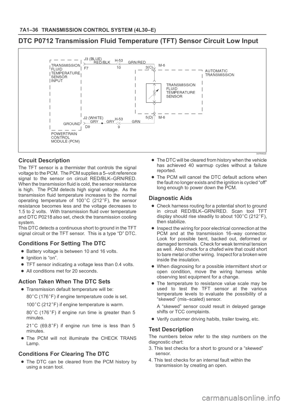
The TFT sensor is a thermister that controls the signal
voltage to the PCM. The PCM supplies a 5–volt reference
signal to the sensor on circuit RED/BLK–GRN/RED.
When the transmission fluid is cold, the sensor resistance
is high. The PCM detects high signal voltage. As the
transmission fluid temperature increases to the normal
operating temperature of 100
C (212F), the sensor
resistance becomes less and the voltage decreases to
1.5 to 2 volts. With transmission fluid over temperature
and DTC P0218 also set, check the transmission cooling
system.
This DTC detects a continuous short to ground in the TFT
signal circuit or the TFT sensor. This is a type “D” DTC.
Conditions For Setting The DTC
Battery voltage is between 10 and 16 volts.
Ignition is “on”.
TFT sensor indicating a voltage less than 0.4 volts.
All conditions met for 20 seconds.
Action Taken When The DTC Sets
Transmission default temperature will be:
80
C (176F) if engine temperature code is set.
100
C (212F) if engine temperature is warm.
80
C (176F) if engine run time is greater than 5
minutes.
21
C (69.8F) if engine run time is less than 5
minutes.
The PCM will not illuminate the CHECK TRANS
Lamp.
Conditions For Clearing The DTC
The DTC can be cleared from the PCM history by
using a scan tool.
The DTC will be cleared from history when the vehicle
has achieved 40 warmup cycles without a failure
reported.
The PCM will cancel the DTC default actions when
the fault no longer exists and the ignition is cycled “off”
long enough to power down the PCM.
Diagnostic Aids
Check harness routing for a potential short to ground
in circuit RED/BLK–GRN/RED. Scan tool TFT
display should rise steadily to about 100
C (212F),
then stabilize.
Inspect the wiring for poor electrical connection at the
PCM and at the transmission 16–way connector.
Look for possible bent, backed out, deformed or
damaged terminals. Check for weak terminal tension
as we ll. A lso ch eck fo r a ch af e d w ire th at cou l d s ho r t
to bare metal or other wiring. Inspect for a broken wire
inside the insulation.
When diagnosing for a possible intermittent short or
open condition, move the wiring harness while
observing test equipment for a change.
The temperature to resistance value scale may be
used to test the TFT sensor at the various
temperature levels to evaluate the possibility of a
“skewed” (mis–scaled) sensor.
A “skewed” sensor could result in delayed garage
shifts or TCC complaints.
Verify customer driving habits, trailer towing, etc.
Test Description
The numbers below refer to the step numbers on the
diagnostic chart:
3. This test checks for a short to ground or a “skewed”
sensor.
4. This test checks for an internal fault within the
transmission by creating an open.
Page 2284 of 6000
TRANSMISSION CONTROL SYSTEM (4L30–E)7A1–39
DTC P0713 Transmission Fluid Temperature (TFT) Sensor Circuit High Input
D07RW029
Circuit Description
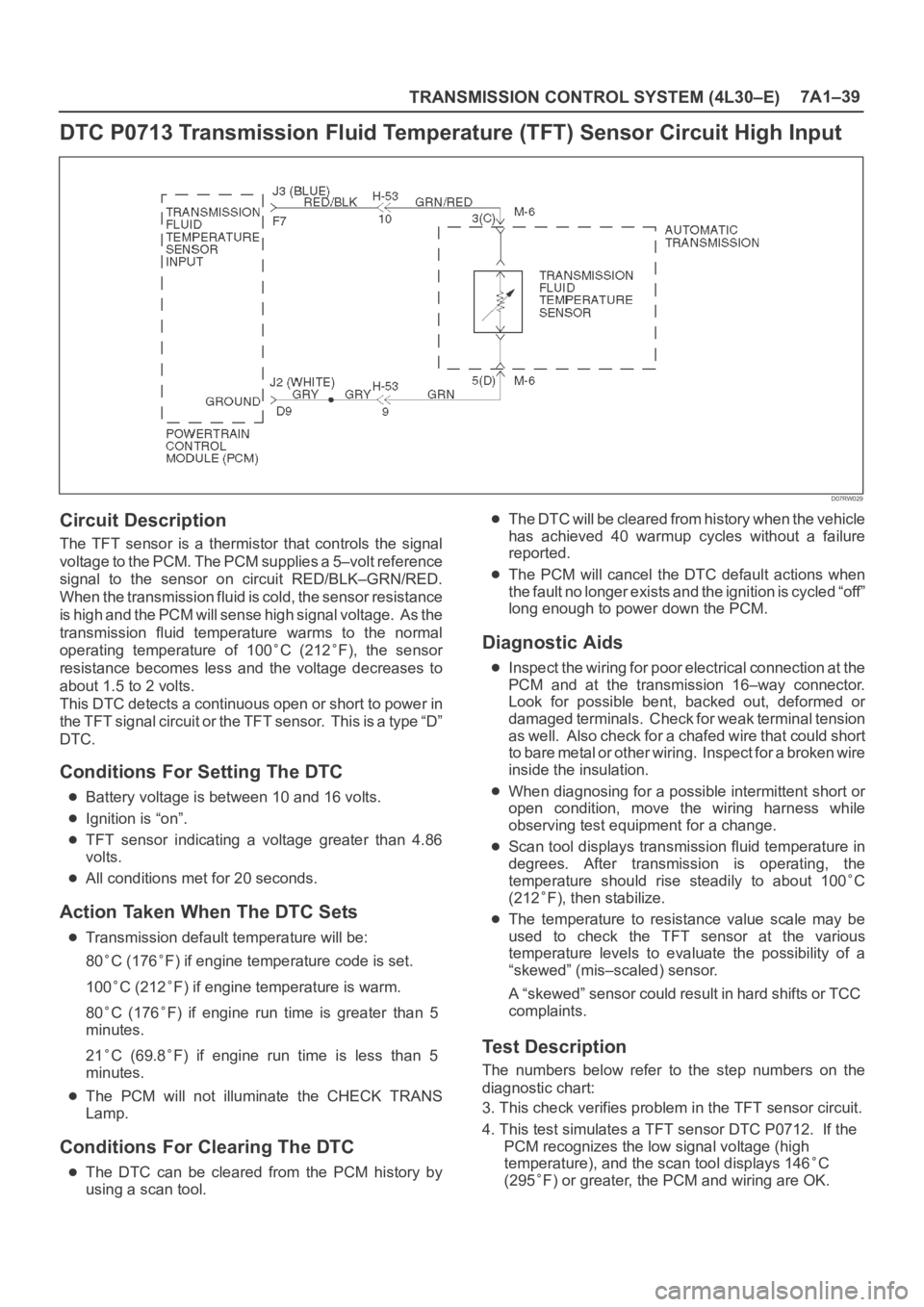
The TFT sensor is a thermistor that controls the signal
voltage to the PCM. The PCM supplies a 5–volt reference
signal to the sensor on circuit RED/BLK–GRN/RED.
When the transmission fluid is cold, the sensor resistance
is high and the PCM will sense high signal voltage. As the
transmission fluid temperature warms to the normal
operating temperature of 100
C (212F), the sensor
resistance becomes less and the voltage decreases to
about 1.5 to 2 volts.
This DTC detects a continuous open or short to power in
the TFT signal circuit or the TFT sensor. This is a type “D”
DTC.
Conditions For Setting The DTC
Battery voltage is between 10 and 16 volts.
Ignition is “on”.
TFT sensor indicating a voltage greater than 4.86
volts.
All conditions met for 20 seconds.
Action Taken When The DTC Sets
Transmission default temperature will be:
80
C (176F) if engine temperature code is set.
100
C (212F) if engine temperature is warm.
80
C (176F) if engine run time is greater than 5
minutes.
21
C (69.8F) if engine run time is less than 5
minutes.
The PCM will not illuminate the CHECK TRANS
Lamp.
Conditions For Clearing The DTC
The DTC can be cleared from the PCM history by
using a scan tool.
The DTC will be cleared from history when the vehicle
has achieved 40 warmup cycles without a failure
reported.
The PCM will cancel the DTC default actions when
the fault no longer exists and the ignition is cycled “off”
long enough to power down the PCM.
Diagnostic Aids
Inspect the wiring for poor electrical connection at the
PCM and at the transmission 16–way connector.
Look for possible bent, backed out, deformed or
damaged terminals. Check for weak terminal tension
as we ll. A lso ch eck fo r a ch af e d w ire th at cou l d s ho r t
to bare metal or other wiring. Inspect for a broken wire
inside the insulation.
When diagnosing for a possible intermittent short or
open condition, move the wiring harness while
observing test equipment for a change.
Scan tool displays transmission fluid temperature in
degrees. After transmission is operating, the
temperature should rise steadily to about 100
C
(212
F), then stabilize.
The temperature to resistance value scale may be
used to check the TFT sensor at the various
temperature levels to evaluate the possibility of a
“skewed” (mis–scaled) sensor.
A “skewed” sensor could result in hard shifts or TCC
complaints.
Test Description
The numbers below refer to the step numbers on the
diagnostic chart:
3. This check verifies problem in the TFT sensor circuit.
4. This test simulates a TFT sensor DTC P0712. If the
PCM recognizes the low signal voltage (high
temperature), and the scan tool displays 146
C
(295
F) or greater, the PCM and wiring are OK.