1998 OPEL FRONTERA Electrical
[x] Cancel search: ElectricalPage 4935 of 6000
6E–278
ENGINE DRIVEABILITY AND EMISSIONS
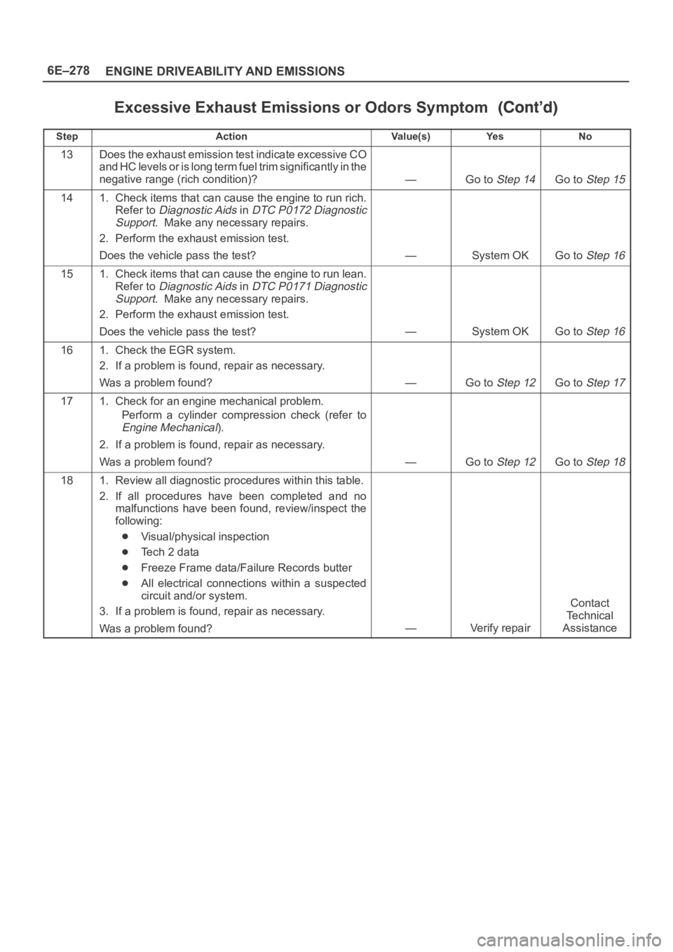
Excessive Exhaust Emissions or Odors Symptom
StepNo Ye s Va l u e ( s ) Action
13Does the exhaust emission test indicate excessive CO
and HC levels or is long term fuel trim significantly in the
negative range (rich condition)?
—Go to Step 14Go to Step 15
141. Check items that can cause the engine to run rich.
Refer to
Diagnostic Aids in DTC P0172 Diagnostic
Support
. Make any necessary repairs.
2. Perform the exhaust emission test.
Does the vehicle pass the test?
—System OKGo to Step 16
151. Check items that can cause the engine to run lean.
Refer to
Diagnostic Aids in DTC P0171 Diagnostic
Support
. Make any necessary repairs.
2. Perform the exhaust emission test.
Does the vehicle pass the test?
—System OKGo to Step 16
161. Check the EGR system.
2. If a problem is found, repair as necessary.
Was a problem found?
—Go to Step 12Go to Step 17
171. Check for an engine mechanical problem.
Perform a cylinder compression check (refer to
Engine Mechanical).
2. If a problem is found, repair as necessary.
Was a problem found?
—Go to Step 12Go to Step 18
181. Review all diagnostic procedures within this table.
2. If all procedures have been completed and no
malfunctions have been found, review/inspect the
following:
Visual/physical inspection
Te c h 2 d a t a
Freeze Frame data/Failure Records butter
All electrical connections within a suspected
circuit and/or system.
3. If a problem is found, repair as necessary.
Was a problem found?
—Verify repair
Contact
Te c h n i c a l
Assistance
Page 4936 of 6000
6E–279 ENGINE DRIVEABILITY AND EMISSIONS
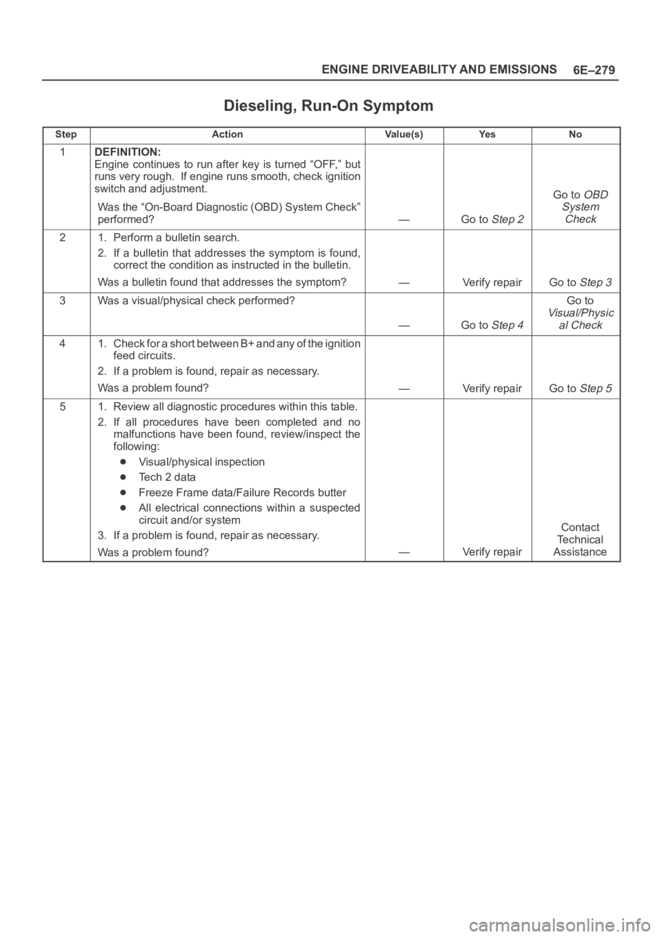
Dieseling, Run-On Symptom
StepActionVa l u e ( s )Ye sNo
1DEFINITION:
Engine continues to run after key is turned “OFF,” but
runs very rough. If engine runs smooth, check ignition
switch and adjustment.
Was the “On-Board Diagnostic (OBD) System Check”
performed?
—Go to Step 2
Go to OBD
System
Check
21. Perform a bulletin search.
2. If a bulletin that addresses the symptom is found,
correct the condition as instructed in the bulletin.
Was a bulletin found that addresses the symptom?
—Verify repairGo to Step 3
3Was a visual/physical check performed?
—Go to Step 4
Go to
Visual/Physic
al Check
41. Check for a short between B+ and any of the ignition
feed circuits.
2. If a problem is found, repair as necessary.
Was a problem found?
—Verify repairGo to Step 5
51. Review all diagnostic procedures within this table.
2. If all procedures have been completed and no
malfunctions have been found, review/inspect the
following:
Visual/physical inspection
Te c h 2 d a t a
Freeze Frame data/Failure Records butter
All electrical connections within a suspected
circuit and/or system
3. If a problem is found, repair as necessary.
Was a problem found?
—Verify repair
Contact
Te c h n i c a l
Assistance
Page 4938 of 6000
6E–281 ENGINE DRIVEABILITY AND EMISSIONS
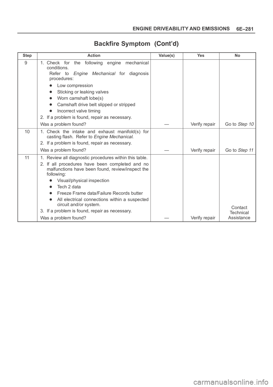
Backfire Symptom
StepNo Ye s Va l u e ( s ) Action
91. Check for the following engine mechanical
conditions.
Refer to
Engine Mechanical for diagnosis
procedures:
Low compression
Sticking or leaking valves
Worn camshaft lobe(s)
Camshaft drive belt slipped or stripped
Incorrect valve timing
2. If a problem is found, repair as necessary.
Was a problem found?
—Verify repairGo to Step 10
101. Check the intake and exhaust manifold(s) for
casting flash. Refer to
Engine Mechanical.
2. If a problem is found, repair as necessary.
Was a problem found?
—Verify repairGo to Step 11
111. Review all diagnostic procedures within this table.
2. If all procedures have been completed and no
malfunctions have been found, review/inspect the
following:
Visual/physical inspection
Te c h 2 d a t a
Freeze Frame data/Failure Records butter
All electrical connections within a suspected
circuit and/or system.
3. If a problem is found, repair as necessary.
Was a problem found?
—Verify repair
Contact
Te c h n i c a l
Assistance
Page 4939 of 6000
6E–282
ENGINE DRIVEABILITY AND EMISSIONS
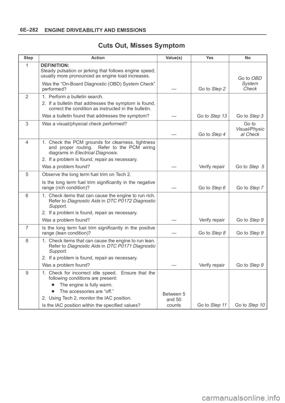
Cuts Out, Misses Symptom
StepActionVa l u e ( s )Ye sNo
1DEFINITION:
Steady pulsation or jerking that follows engine speed;
usually more pronounced as engine load increases.
Was the “On-Board Diagnostic (OBD) System Check”
performed?
—Go to Step 2
Go to OBD
System
Check
21. Perform a bulletin search.
2. If a bulletin that addresses the symptom is found,
correct the condition as instructed in the bulletin.
Was a bulletin found that addresses the symptom?
—Go to Step 13Go to Step 3
3Was a visual/physical check performed?
—Go to Step 4
Go to
Visual/Physic
al Check
41. Check the PCM grounds for clearness, tightness
and proper routing. Refer to the PCM wiring
diagrams in
Electrical Diagnosis.
2. If a problem is found, repair as necessary.
Was a problem found?
—Verify repairGo to Step 5
5Observe the long term fuel trim on Tech 2.
Is the long term fuel trim significantly in the negative
range (rich condition)?
—Go to Step 6Go to Step 7
61. Check items that can cause the engine to run rich.
Refer to
Diagnostic Aids in DTC P0172 Diagnostic
Support
.
2. If a problem is found, repair as necessary.
Was a problem found?
—Verify repairGo to Step 9
7Is the long term fuel trim significantly in the positive
range (lean condition)?
—Go to Step 8Go to Step 9
81. Check items that can cause the engine to run lean.
Refer to
Diagnostic Aids in DTC P0171 Diagnostic
Support
.
2. If a problem is found, repair as necessary.
Was a problem found?
—Verify repairGo to Step 9
91. Check for incorrect idle speed. Ensure that the
following conditions are present:
The engine is fully warm.
The accessories are “off.”
2. Using Tech 2, monitor the IAC position.
Is the IAC position within the specified values?Between 5
and 50
counts
Go to Step 11Go to Step 10
Page 4941 of 6000
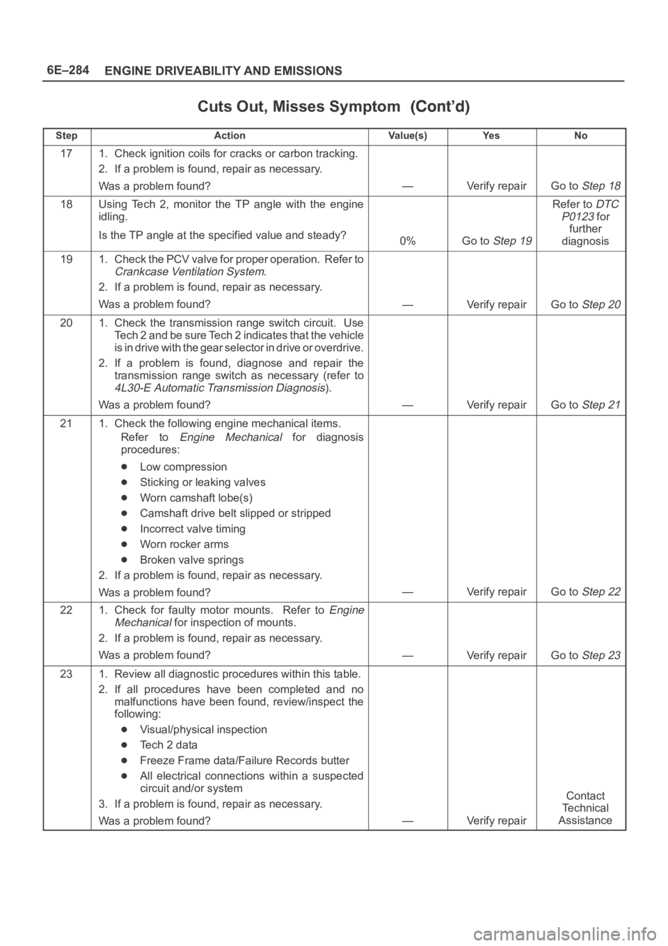
6E–284
ENGINE DRIVEABILITY AND EMISSIONS
Cuts Out, Misses Symptom
StepNo Ye s Va l u e ( s ) Action
171. Check ignition coils for cracks or carbon tracking.
2. If a problem is found, repair as necessary.
Was a problem found?
—Verify repairGo to Step 18
18Using Tech 2, monitor the TP angle with the engine
idling.
Is the TP angle at the specified value and steady?
0%Go to Step 19
Refer to DTC
P0123
for
further
diagnosis
191. Check the PCV valve for proper operation. Refer to
Crankcase Ventilation System.
2. If a problem is found, repair as necessary.
Was a problem found?
—Verify repairGo to Step 20
201. Check the transmission range switch circuit. Use
Tech 2 and be sure Tech 2 indicates that the vehicle
is in drive with the gear selector in drive or overdrive.
2. If a problem is found, diagnose and repair the
transmission range switch as necessary (refer to
4L30-E Automatic Transmission Diagnosis).
Was a problem found?
—Verify repairGo to Step 21
211. Check the following engine mechanical items.
Refer to
Engine Mechanical for diagnosis
procedures:
Low compression
Sticking or leaking valves
Worn camshaft lobe(s)
Camshaft drive belt slipped or stripped
Incorrect valve timing
Worn rocker arms
Broken valve springs
2. If a problem is found, repair as necessary.
Was a problem found?
—Verify repairGo to Step 22
221. Check for faulty motor mounts. Refer to Engine
Mechanical
for inspection of mounts.
2. If a problem is found, repair as necessary.
Was a problem found?
—Verify repairGo to Step 23
231. Review all diagnostic procedures within this table.
2. If all procedures have been completed and no
malfunctions have been found, review/inspect the
following:
Visual/physical inspection
Te c h 2 d a t a
Freeze Frame data/Failure Records butter
All electrical connections within a suspected
circuit and/or system
3. If a problem is found, repair as necessary.
Was a problem found?
—Verify repair
Contact
Te c h n i c a l
Assistance
Page 4943 of 6000
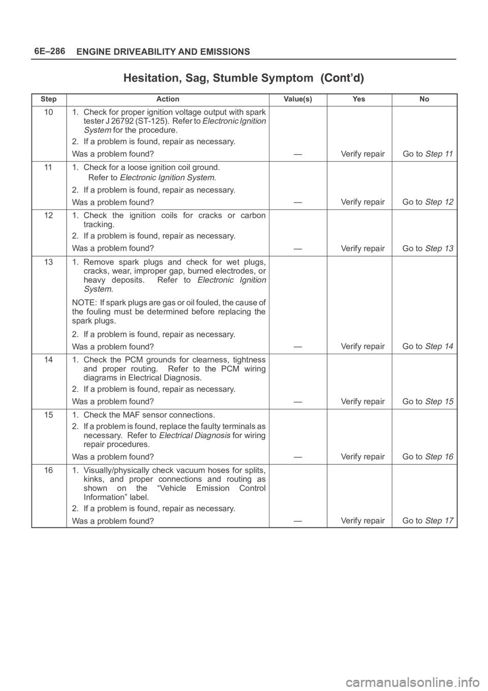
6E–286
ENGINE DRIVEABILITY AND EMISSIONS
Hesitation, Sag, Stumble Symptom
StepNo Ye s Va l u e ( s ) Action
101. Check for proper ignition voltage output with spark
tester J 26792 (ST-125). Refer to
Electronic Ignition
System
for the procedure.
2. If a problem is found, repair as necessary.
Was a problem found?
—Verify repairGo to Step 11
111. Check for a loose ignition coil ground.
Refer to
Electronic Ignition System.
2. If a problem is found, repair as necessary.
Was a problem found?
—Verify repairGo to Step 12
121. Check the ignition coils for cracks or carbon
tracking.
2. If a problem is found, repair as necessary.
Was a problem found?
—Verify repairGo to Step 13
131. Remove spark plugs and check for wet plugs,
cracks, wear, improper gap, burned electrodes, or
heavy deposits. Refer to
Electronic Ignition
System
.
NOTE: If spark plugs are gas or oil fouled, the cause of
the fouling must be determined before replacing the
spark plugs.
2. If a problem is found, repair as necessary.
Was a problem found?
—Verify repairGo to Step 14
141. Check the PCM grounds for clearness, tightness
and proper routing. Refer to the PCM wiring
diagrams in Electrical Diagnosis.
2. If a problem is found, repair as necessary.
Was a problem found?
—Verify repairGo to Step 15
151. Check the MAF sensor connections.
2. If a problem is found, replace the faulty terminals as
necessary. Refer to
Electrical Diagnosis for wiring
repair procedures.
Was a problem found?
—Verify repairGo to Step 16
161. Visually/physically check vacuum hoses for splits,
kinks, and proper connections and routing as
shown on the “Vehicle Emission Control
Information” label.
2. If a problem is found, repair as necessary.
Was a problem found?
—Verify repairGo to Step 17
Page 4944 of 6000
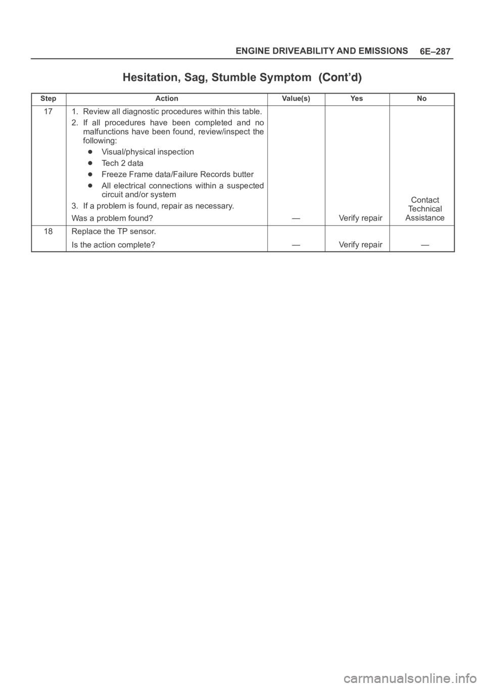
6E–287 ENGINE DRIVEABILITY AND EMISSIONS
Hesitation, Sag, Stumble Symptom
StepNo Ye s Va l u e ( s ) Action
171. Review all diagnostic procedures within this table.
2. If all procedures have been completed and no
malfunctions have been found, review/inspect the
following:
Visual/physical inspection
Te c h 2 d a t a
Freeze Frame data/Failure Records butter
All electrical connections within a suspected
circuit and/or system
3. If a problem is found, repair as necessary.
Was a problem found?
—Verify repair
Contact
Te c h n i c a l
Assistance
18Replace the TP sensor.
Is the action complete?
—Verify repair—
Page 4945 of 6000
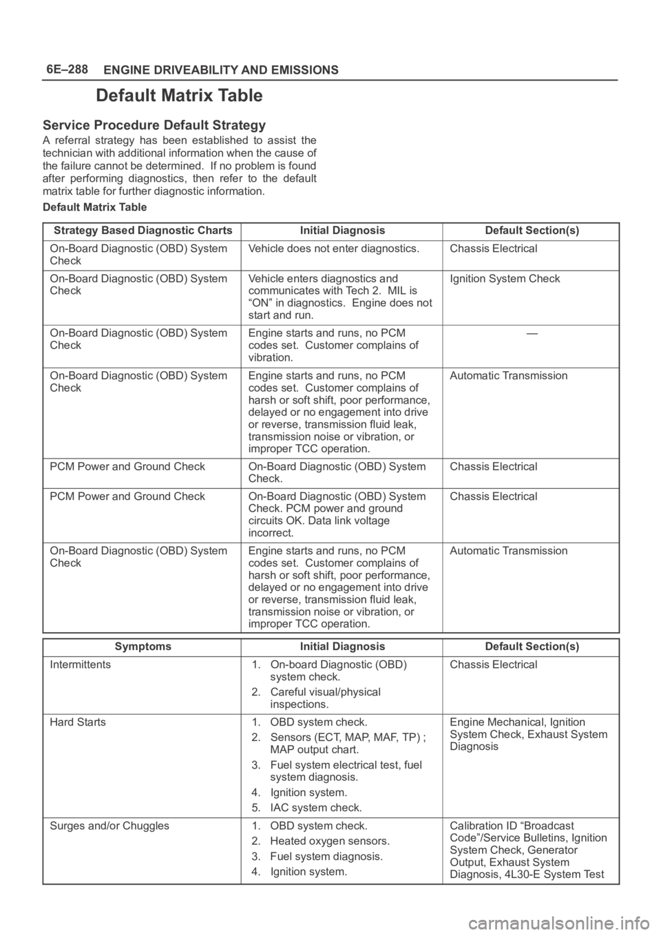
6E–288
ENGINE DRIVEABILITY AND EMISSIONS
Default Matrix Table
Service Procedure Default Strategy
A referral strategy has been established to assist the
technician with additional information when the cause of
the failure cannot be determined. If no problem is found
after performing diagnostics, then refer to the default
matrix table for further diagnostic information.
Default Matrix Table
Strategy Based Diagnostic Charts
Initial DiagnosisDefault Section(s)
On-Board Diagnostic (OBD) System
CheckVehicle does not enter diagnostics.Chassis Electrical
On-Board Diagnostic (OBD) System
CheckVehicle enters diagnostics and
communicates with Tech 2. MIL is
“ON” in diagnostics. Engine does not
start and run.Ignition System Check
On-Board Diagnostic (OBD) System
CheckEngine starts and runs, no PCM
codes set. Customer complains of
vibration.—
On-Board Diagnostic (OBD) System
CheckEngine starts and runs, no PCM
codes set. Customer complains of
harsh or soft shift, poor performance,
delayed or no engagement into drive
or reverse, transmission fluid leak,
transmission noise or vibration, or
improper TCC operation.Automatic Transmission
PCM Power and Ground CheckOn-Board Diagnostic (OBD) System
Check.Chassis Electrical
PCM Power and Ground CheckOn-Board Diagnostic (OBD) System
Check. PCM power and ground
circuits OK. Data link voltage
incorrect.Chassis Electrical
On-Board Diagnostic (OBD) System
CheckEngine starts and runs, no PCM
codes set. Customer complains of
harsh or soft shift, poor performance,
delayed or no engagement into drive
or reverse, transmission fluid leak,
transmission noise or vibration, or
improper TCC operation.Automatic Transmission
SymptomsInitial DiagnosisDefault Section(s)
Intermittents1. On-board Diagnostic (OBD)
system check.
2. Careful visual/physical
inspections.Chassis Electrical
Hard Starts1. OBD system check.
2. Sensors (ECT, MAP, MAF, TP) ;
MAP output chart.
3. Fuel system electrical test, fuel
system diagnosis.
4. Ignition system.
5. IAC system check.Engine Mechanical, Ignition
System Check, Exhaust System
Diagnosis
Surges and/or Chuggles1. OBD system check.
2. Heated oxygen sensors.
3. Fuel system diagnosis.
4. Ignition system.Calibration ID “Broadcast
Code”/Service Bulletins, Ignition
System Check, Generator
Output, Exhaust System
Diagnosis, 4L30-E System Test