1998 OPEL FRONTERA check engine light
[x] Cancel search: check engine lightPage 1215 of 6000

6E–98
ENGINE DRIVEABILITY AND EMISSIONS
Exhaust Gas Recirculation (EGR) System Check
StepActionVa l u e ( s )Ye sNo
1Check the EGR valve for looseness.
Is the EGR valve Loose?
—Go to Step 2Go to Step 3
2Tighten the EGR valve.
Is the action complete?
—Verify repair—
31. Place the transmission selector in Park or Neutral.
2. Start the engine and idle until warm.
3. Using Tech 2, command EGR “50% ON.”
Does the engine idle rough and lose RPMs?
—
EGR system
working
properly. No
problem
found.
Go to Step 4
41. Engine “OFF.”
2. Ignition “ON.”
3. Using a test light to ground, check the EGR harness
between the EGR valve and the ignition feed.
Does the test light illuminate?
—Go to Step 6Go to Step 5
5Repair the EGR harness ignition feed.
Was the problem corrected?
—Verify repairGo to Step 6
61. Remove the EGR valve.
2. Visually and physically inspect the EGR valve
pintle, valve passages and adapter for excessive
deposits, obstructions or any restrictions.
Does the EGR valve have excessive deposits,
obstructions or any restrictions?
—Go to Step 7Go to Step 8
7Clean or replace EGR system components as
necessary.
Was the problem corrected?
—Verify repairGo to Step 8
81. Ground the EGR valve metal case to battery (–).
2. Using Tech 2, command EGR “ON” and observe the
EGR valve pintle for movement.
Does the EGR valve pintle move according to
command?
—Go to Step 9
Go to DTC
P1406 chart
91. Remove the EGR inlet and outlet pipes from the
intake and exhaust manifolds.
2. Visually and physically inspect manifold EGR ports
and EGR inlet and outlet pipes for blockage or
restriction caused by excessive deposits or other
damage.
Do the manifold EGR ports or inlet and outlet pipes
have excessive deposits, obstructions, or any
restrictions?
—Go to Step 10
EGR system
working
properly. No
problem
found.
10Clean or replace EGR system components as
necessary.
Is the action complete?
—Verify repair—
Page 1218 of 6000

6E–101 ENGINE DRIVEABILITY AND EMISSIONS
PCM Diagnostic Trouble Codes
The following table lists the diagnostic trouble codes
supported by this vehicle application. If any DTCs not
listed here are displayed by a Tech 2, the Tech 2 data may
be faulty; notify the Tech 2 manufacturer of any DTCs
displayed that are not included in the following table.
A - Emission related P-code, check engine light on as
soon as a failure detected.
B - Emission related P-code, check engine light on if a
failure detected in two consecutive trips.
C - Non emission related P-code, check engine light on
if a failure detected in one trip.
D - Non emission related P-code, no check engine
light, but P-code will be set if a failure detected.
X - Do not check.
Page 1223 of 6000
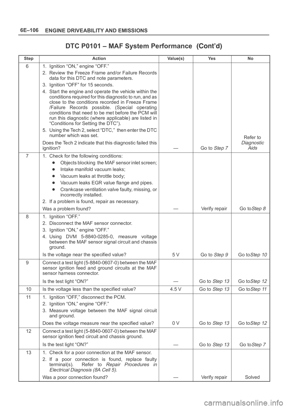
6E–106
ENGINE DRIVEABILITY AND EMISSIONS
DTC P0101 – MAF System Performance
StepNo Ye s Va l u e ( s ) Action
61. Ignition “ON,” engine “OFF.”
2. Review the Freeze Frame and/or Failure Records
data for this DTC and note parameters.
3. Ignition “OFF” for 15 seconds.
4. Start the engine and operate the vehicle within the
conditions required for this diagnostic to run, and as
close to the conditions recorded in Freeze Frame
/Failure Records possible. (Special operating
conditions that need to be met before the PCM will
run this diagnostic (where applicable) are listed in
“Conditions for Setting the DTC”).
5. Using the Tech 2, select “DTC,” then enter the DTC
number which was set.
Does the Tech 2 indicate that this diagnostic failed this
ignition?
—Go to Step 7
Refer to
Diagnostic
Aids
71. Check for the following conditions:
Objects blocking the MAF sensor inlet screen;
Intake manifold vacuum leaks;
Vacuum leaks at throttle body;
Vacuum leaks EGR value flange and pipes.
Crankcase ventilation valve faulty, missing, or
incorrectly installed.
2. If a problem is found, repair as necessary.
Was a problem found?
—Verify repairGo toStep 8
81. Ignition “OFF.”
2. Disconnect the MAF sensor connector.
3. Ignition “ON,” engine “OFF.”
4. Using DVM 5-8840-0285-0, measure voltage
between the MAF sensor signal circuit and chassis
ground.
Is the voltage near the specified value?
5 VGo to Step 9Go toStep 10
9Connect a test light (5-8840-0607-0) between the MAF
sensor ignition feed and ground circuits at the MAF
sensor harness connector.
Is the test light “ON?”
—Go to Step 13Go toStep 12
10Is the voltage less than the specified value?4.5 VGo to Step 13Go toStep 11
111. Ignition “OFF,” disconnect the PCM.
2. Ignition “ON,” engine “OFF.”
3. Measure voltage between the MAF signal circuit
and ground.
Does the voltage measure near the specified value?
0 VGo to Step 13Go toStep 12
12Connect a test light (5-8840-0607-0) between the MAF
sensor ignition feed circuit and chassis ground.
Is the test light “ON?”
—Go to Step 13Go toStep 7
131. Check for a poor connection at the MAF sensor.
2. If a poor connection is found, replace faulty
terminal(s). Refer to
Repair Procedures in
Electrical Diagnosis (8A Cell 5).
Was a poor connection found?—Verify repairSolved
Page 1225 of 6000
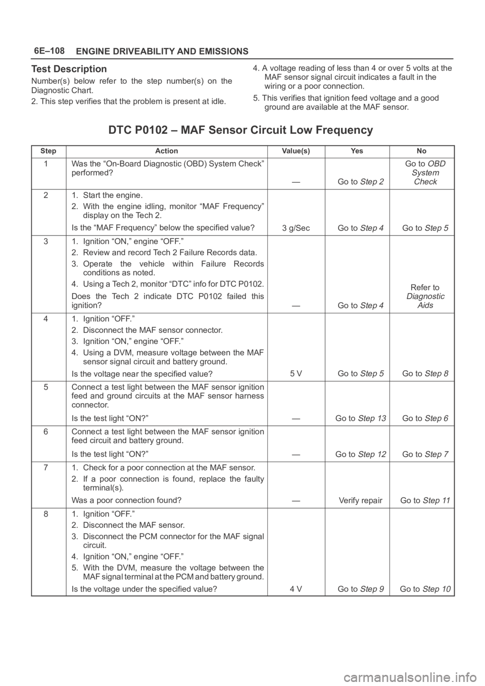
6E–108
ENGINE DRIVEABILITY AND EMISSIONS
Test Description
Number(s) below refer to the step number(s) on the
Diagnostic Chart.
2. This step verifies that the problem is present at idle.4. A voltage reading of less than 4 or over 5 volts at the
MAF sensor signal circuit indicates a fault in the
wiring or a poor connection.
5. This verifies that ignition feed voltage and a good
ground are available at the MAF sensor.
DTC P0102 – MAF Sensor Circuit Low Frequency
StepActionVa l u e ( s )Ye sNo
1Was the “On-Board Diagnostic (OBD) System Check”
performed?
—Go to Step 2
Go to OBD
System
Check
21. Start the engine.
2. With the engine idling, monitor “MAF Frequency”
display on the Tech 2.
Is the “MAF Frequency” below the specified value?
3g/SecGo to Step 4Go to Step 5
31. Ignition “ON,” engine “OFF.”
2. Review and record Tech 2 Failure Records data.
3. Operate the vehicle within Failure Records
conditions as noted.
4. Using a Tech 2, monitor “DTC” info for DTC P0102.
Does the Tech 2 indicate DTC P0102 failed this
ignition?
—Go to Step 4
Refer to
Diagnostic
Aids
41. Ignition “OFF.”
2. Disconnect the MAF sensor connector.
3. Ignition “ON,” engine “OFF.”
4. Using a DVM, measure voltage between the MAF
sensor signal circuit and battery ground.
Is the voltage near the specified value?
5 VGo to Step 5Go to Step 8
5Connect a test light between the MAF sensor ignition
feed and ground circuits at the MAF sensor harness
connector.
Is the test light “ON?”
—Go to Step 13Go to Step 6
6Connect a test light between the MAF sensor ignition
feed circuit and battery ground.
Is the test light “ON?”
—Go to Step 12Go to Step 7
71. Check for a poor connection at the MAF sensor.
2. If a poor connection is found, replace the faulty
terminal(s).
Was a poor connection found?
—Verify repairGo to Step 11
81. Ignition “OFF.”
2. Disconnect the MAF sensor.
3. Disconnect the PCM connector for the MAF signal
circuit.
4. Ignition “ON,” engine “OFF.”
5. With the DVM, measure the voltage between the
MAF signal terminal at the PCM and battery ground.
Is the voltage under the specified value?
4 VGo to Step 9Go to Step 10
Page 1230 of 6000
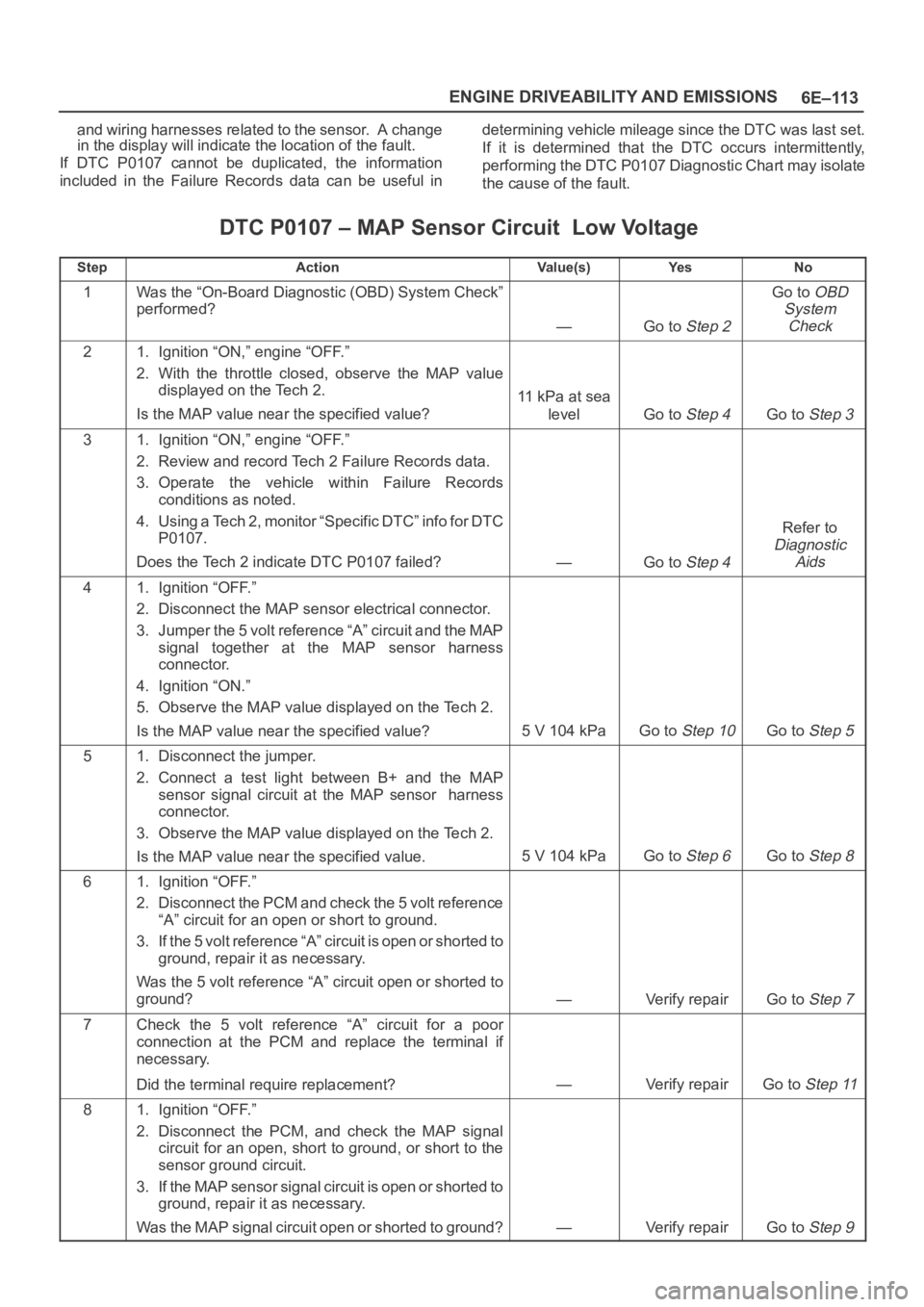
6E–113 ENGINE DRIVEABILITY AND EMISSIONS
and wiring harnesses related to the sensor. A change
in the display will indicate the location of the fault.
If DTC P0107 cannot be duplicated, the information
included in the Failure Records data can be useful indetermining vehicle mileage since the DTC was last set.
If it is determined that the DTC occurs intermittently,
performing the DTC P0107 Diagnostic Chart may isolate
the cause of the fault.
DTC P0107 – MAP Sensor Circuit Low Voltage
StepActionVa l u e ( s )Ye sNo
1Was the “On-Board Diagnostic (OBD) System Check”
performed?
—Go to Step 2
Go to OBD
System
Check
21. Ignition “ON,” engine “OFF.”
2. With the throttle closed, observe the MAP value
displayed on the Tech 2.
Is the MAP value near the specified value?
11 kPa at sea
level
Go to Step 4Go to Step 3
31. Ignition “ON,” engine “OFF.”
2. Review and record Tech 2 Failure Records data.
3. Operate the vehicle within Failure Records
conditions as noted.
4. Using a Tech 2, monitor “Specific DTC” info for DTC
P0107.
Does the Tech 2 indicate DTC P0107 failed?
—Go to Step 4
Refer to
Diagnostic
Aids
41. Ignition “OFF.”
2. Disconnect the MAP sensor electrical connector.
3. Jumper the 5 volt reference “A” circuit and the MAP
signal together at the MAP sensor harness
connector.
4. Ignition “ON.”
5. Observe the MAP value displayed on the Tech 2.
Is the MAP value near the specified value?
5 V 104 kPaGo to Step 10Go to Step 5
51. Disconnect the jumper.
2. Connect a test light between B+ and the MAP
sensor signal circuit at the MAP sensor harness
connector.
3. Observe the MAP value displayed on the Tech 2.
Is the MAP value near the specified value.
5 V 104 kPaGo to Step 6Go to Step 8
61. Ignition “OFF.”
2. Disconnect the PCM and check the 5 volt reference
“A” circuit for an open or short to ground.
3. If the 5 volt reference “A” circuit is open or shorted to
ground, repair it as necessary.
Was the 5 volt reference “A” circuit open or shorted to
ground?
—Verify repairGo to Step 7
7Check the 5 volt reference “A” circuit for a poor
connection at the PCM and replace the terminal if
necessary.
Did the terminal require replacement?
—Verify repairGo to Step 11
81. Ignition “OFF.”
2. Disconnect the PCM, and check the MAP signal
circuit for an open, short to ground, or short to the
sensor ground circuit.
3. If the MAP sensor signal circuit is open or shorted to
ground, repair it as necessary.
Was the MAP signal circuit open or shorted to ground?
—Verify repairGo to Step 9
Page 1233 of 6000
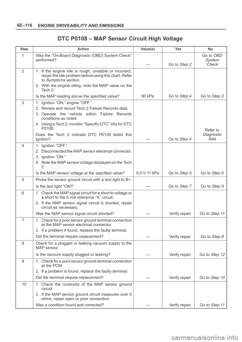
6E–116
ENGINE DRIVEABILITY AND EMISSIONS
DTC P0108 – MAP Sensor Circuit High Voltage
StepActionVa l u e ( s )Ye sNo
1Was the “On-Board Diagnostic (OBD) System Check”
performed?
—Go to Step 2
Go to OBD
System
Check
21. If the engine idle is rough, unstable or incorrect,
repair the idle problem before using this chart. Refer
to
Symptoms section.
2. With the engine idling, note the MAP value on the
Te c h 2 .
Is the MAP reading above the specified value?
90 kPaGo to Step 4Go to Step 3
31. Ignition “ON,” engine “OFF.”
2. Review and record Tech 2 Failure Records data.
3. Operate the vehicle within Failure Records
conditions as noted.
4. Using a Tech 2, monitor “Specific DTC” info for DTC
P0108.
Does the Tech 2 indicate DTC P0108 failed this
ignition?
—Go to Step 4
Refer to
Diagnostic
Aids
41. Ignition “OFF.”
2. Disconnected the MAP sensor electrical connector.
3. Ignition “ON.”
4. Note the MAP sensor voltage displayed on the Tech
2.
Is the MAP sensor voltage at the specified value?
0.0 V 11 kPaGo to Step 5Go to Step 6
5Probe the sensor ground circuit with a test light to B+.
Is the test light “ON?”
—Go to Step 7Go to Step 9
61. Check the MAP signal circuit for a short to voltage or
a short to the 5 volt reference “A” circuit.
2. If the MAP sensor signal circuit is shorted, repair
circuit as necessary.
Was the MAP sensor signal circuit shorted?
—Verify repairGo to Step 11
71. Check for a poor sensor ground terminal connection
at the MAP sensor electrical connector.
2. If a problem if found, replace the faulty terminal.
Did the terminal require replacement?
—Verify repairGo to Step 8
8Check for a plugged or leaking vacuum supply to the
MAP sensor.
Is the vacuum supply plugged or leaking?
—Verify repairGo to Step 12
91. Check for a poor sensor ground terminal connection
at the PCM.
2. If a problem is found, replace the faulty terminal.
Did the terminal require replacement?
—Verify repairGo to Step 10
101. Check the continuity of the MAP sensor ground
circuit.
2. If the MAP sensor ground circuit measures over 5
ohms, repair open or poor connection.
Was a condition found and corrected?
—Verify repairGo to Step 11
Page 1248 of 6000
6E–131 ENGINE DRIVEABILITY AND EMISSIONS
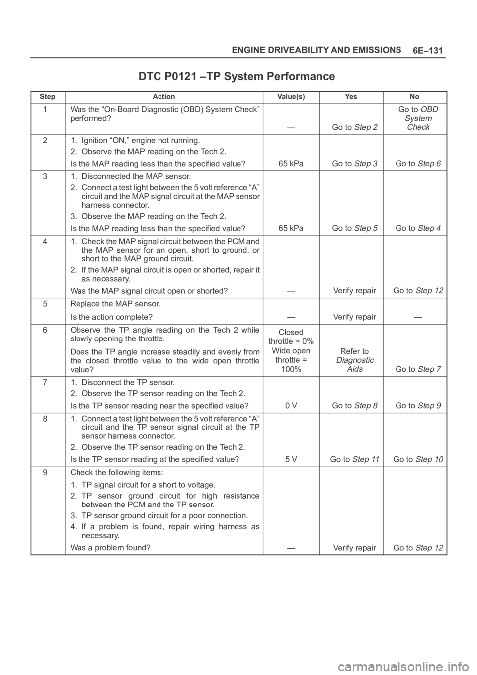
DTC P0121 –TP System Performance
StepActionVa l u e ( s )Ye sNo
1Was the “On-Board Diagnostic (OBD) System Check”
performed?
—Go to Step 2
Go to OBD
System
Check
21. Ignition “ON,” engine not running.
2. Observe the MAP reading on the Tech 2.
Is the MAP reading less than the specified value?
65 kPaGo to Step 3Go to Step 6
31. Disconnected the MAP sensor.
2. Connect a test light between the 5 volt reference “A”
circuit and the MAP signal circuit at the MAP sensor
harness connector.
3. Observe the MAP reading on the Tech 2.
Is the MAP reading less than the specified value?
65 kPaGo to Step 5Go to Step 4
41. Check the MAP signal circuit between the PCM and
the MAP sensor for an open, short to ground, or
short to the MAP ground circuit.
2. If the MAP signal circuit is open or shorted, repair it
as necessary.
Was the MAP signal circuit open or shorted?
—Verify repairGo to Step 12
5Replace the MAP sensor.
Is the action complete?
—Verify repair—
6Observe the TP angle reading on the Tech 2 while
slowly opening the throttle.
Does the TP angle increase steadily and evenly from
the closed throttle value to the wide open throttle
value?Closed
throttle = 0%
Wide open
throttle =
100%
Refer to
Diagnostic
Aids
Go to Step 7
71. Disconnect the TP sensor.
2. Observe the TP sensor reading on the Tech 2.
Is the TP sensor reading near the specified value?
0 VGo to Step 8Go to Step 9
81. Connect a test light between the 5 volt reference “A”
circuit and the TP sensor signal circuit at the TP
sensor harness connector.
2. Observe the TP sensor reading on the Tech 2.
Is the TP sensor reading at the specified value?
5 VGo to Step 11Go to Step 10
9Check the following items:
1. TP signal circuit for a short to voltage.
2. TP sensor ground circuit for high resistance
between the PCM and the TP sensor.
3. TP sensor ground circuit for a poor connection.
4. If a problem is found, repair wiring harness as
necessary.
Was a problem found?
—Verify repairGo to Step 12
Page 1251 of 6000
6E–134
ENGINE DRIVEABILITY AND EMISSIONS
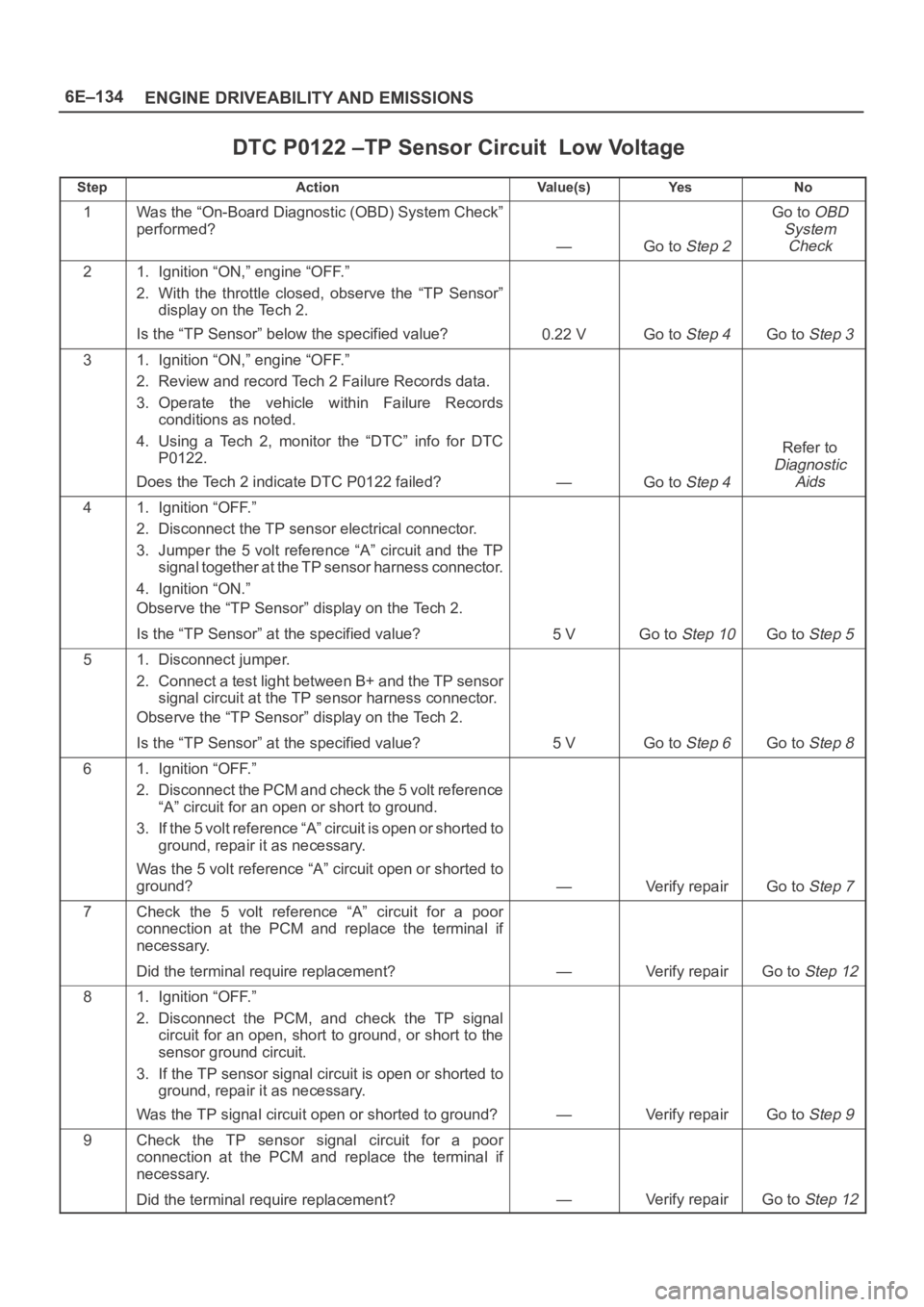
DTC P0122 –TP Sensor Circuit Low Voltage
StepActionVa l u e ( s )Ye sNo
1Was the “On-Board Diagnostic (OBD) System Check”
performed?
—Go to Step 2
Go to OBD
System
Check
21. Ignition “ON,” engine “OFF.”
2. With the throttle closed, observe the “TP Sensor”
display on the Tech 2.
Is the “TP Sensor” below the specified value?
0.22 VGo to Step 4Go to Step 3
31. Ignition “ON,” engine “OFF.”
2. Review and record Tech 2 Failure Records data.
3. Operate the vehicle within Failure Records
conditions as noted.
4. Using a Tech 2, monitor the “DTC” info for DTC
P0122.
Does the Tech 2 indicate DTC P0122 failed?
—Go to Step 4
Refer to
Diagnostic
Aids
41. Ignition “OFF.”
2. Disconnect the TP sensor electrical connector.
3. Jumper the 5 volt reference “A” circuit and the TP
signal together at the TP sensor harness connector.
4. Ignition “ON.”
Observe the “TP Sensor” display on the Tech 2.
Is the “TP Sensor” at the specified value?
5 VGo to Step 10Go to Step 5
51. Disconnect jumper.
2. Connect a test light between B+ and the TP sensor
signal circuit at the TP sensor harness connector.
Observe the “TP Sensor” display on the Tech 2.
Is the “TP Sensor” at the specified value?
5 VGo to Step 6Go to Step 8
61. Ignition “OFF.”
2. Disconnect the PCM and check the 5 volt reference
“A” circuit for an open or short to ground.
3. If the 5 volt reference “A” circuit is open or shorted to
ground, repair it as necessary.
Was the 5 volt reference “A” circuit open or shorted to
ground?
—Verify repairGo to Step 7
7Check the 5 volt reference “A” circuit for a poor
connection at the PCM and replace the terminal if
necessary.
Did the terminal require replacement?
—Verify repairGo to Step 12
81. Ignition “OFF.”
2. Disconnect the PCM, and check the TP signal
circuit for an open, short to ground, or short to the
sensor ground circuit.
3. If the TP sensor signal circuit is open or shorted to
ground, repair it as necessary.
Was the TP signal circuit open or shorted to ground?
—Verify repairGo to Step 9
9Check the TP sensor signal circuit for a poor
connection at the PCM and replace the terminal if
necessary.
Did the terminal require replacement?
—Verify repairGo to Step 12