1998 OPEL FRONTERA Electrical
[x] Cancel search: ElectricalPage 4622 of 6000
ENGINE ELECTRICAL6D1–3
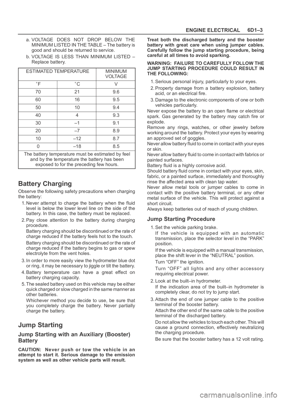
a. VOLTAGE DOES NOT DROP BELOW THE
MINIMUM LISTED IN THE TABLE – The battery is
good and should be returned to service.
b. VOLTAGE IS LESS THAN MINIMUM LISTED –
Replace battery.
ESTIMATED TEMPERATURE
MINIMUM
VOLTAGE
FCV
70219.6
60169.5
50109.4
4049.3
30–19.1
20–78.9
10–128.7
0–188.5
The battery temperature must be estimated by feel
and by the temperature the battery has been
exposed to for the preceding few hours.
Battery Charging
Observe the following safety precautions when charging
the battery:
1. Never attempt to charge the battery when the fluid
level is below the lower level line on the side of the
battery. In this case, the battery must be replaced.
2. Pay close attention to the battery during charging
procedure.
Battery charging should be discontinued or the rate of
charge reduced if the battery feels hot to the touch.
Battery charging should be discontinued or the rate of
charge reduced if the battery begins to gas or spew
electrolyte from the vent holes.
3. In order to more easily view the hydrometer blue dot
or ring, it may be necessary to jiggle or tilt the battery.
4. Battery temperature can have a great effect on
battery charging capacity.
5. The sealed battery used on this vehicle may be either
quick charged or slow charged in the same manner as
other batteries.
Whichever method you decide to use, be sure that
you completely charge the battery. Never partially
charge the battery.
Jump Starting
Jump Starting with an Auxiliary (Booster)
Battery
CAUTION: Never push or tow the vehicle in an
attempt to start it. Serious damage to the emission
system as well as other vehicle parts will result.Treat both the discharged battery and the booster
battery with great care when using jumper cables.
Carefully follow the jump starting procedure, being
careful at all times to avoid sparking.
WARNING: FAILURE TO CAREFULLY FOLLOW THE
JUMP STARTING PROCEDURE COULD RESULT IN
THE FOLLOWING:
1. Serious personal injury, particularly to your eyes.
2. Property damage from a battery explosion, battery
acid, or an electrical fire.
3. Damage to the electronic components of one or both
vehicles particularly.
Never expose the battery to an open flame or electrical
spark. Gas generated by the battery may catch fire or
explode.
Remove any rings, watches, or other jewelry before
working around the battery. Protect your eyes by wearing
an approved set of goggles.
Never allow battery fluid to come in contact with your eyes
or skin.
Never allow battery fluid to come in contact with fabrics or
painted surfaces.
Battery fluid is a highly corrosive acid.
Should battery fluid come in contact with your eyes, skin,
fabric, or a painted surface, immediately and thoroughly
rinse the affected area with clean tap water.
Never allow metal tools or jumper cables to come in
contact with the positive battery terminal, or any other
metal surface of the vehicle. This will protect against a
short circuit.
Always keep batteries out of reach of young children.
Jump Starting Procedure
1. Set the vehicle parking brake.
If the vehicle is equipped with an automatic
transmission, place the selector level in the “PARK”
position.
If the vehicle is equipped with a manual transmission,
place the shift lever in the “NEUTRAL” position.
Turn “OFF” the ignition.
Turn “OFF” all lights and any other accessory
requiring electrical power.
2. Look at the built–in hydrometer.
If the indication area of the built–in hydrometer is
completely clear, do not try to jump start.
3. Attach the end of one jumper cable to the positive
terminal of the booster battery.
Attach the other end of the same cable to the positive
terminal of the discharged battery.
Do not allow the vehicles to touch each other. This will
cause a ground connection, effectively neutralizing
the charging procedure.
Be sure that the booster battery has a 12 volt rating.
Page 4623 of 6000
6D1–4
ENGINE ELECTRICAL
4. Attach one end of the remaining cable to the negative
terminal of the booster battery.
Attach the other end of the same cable to a solid
engine ground (such as the air conditioning
compressor bracket or the generator mounting
bracket) of the vehicle with the discharged battery.
The ground connection must be at least 450 mm (18
in.) from the battery of the vehicle whose battery is
being charged.
WARNING: NEVER ATTACH THE END OF THE
JUMPER CABLE DIRECTLY TO THE NEGATIVE
TERMINAL OF THE DEAD BATTERY.
5. Start the engine of the vehicle with the good battery.
Make sure that all unnecessary electrical accessories
have been turned “OFF”.
6. Start the engine of the vehicle with the dead battery.
7. To remove the jumper cables, follow the above
directions in reverse order.
Be sure to first disconnect the negative cable from the
vehicle with the discharged battery.
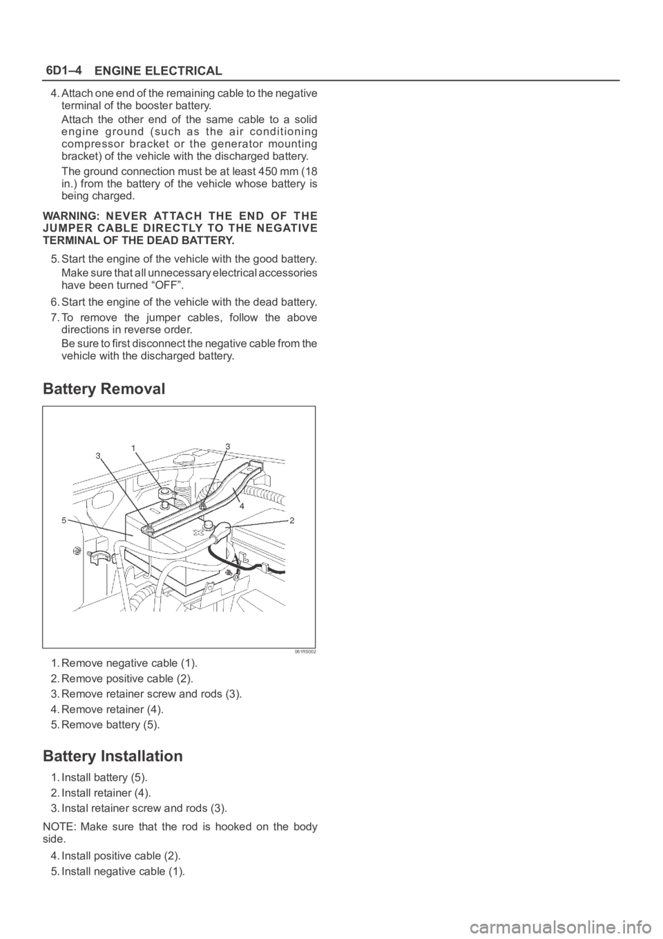
Battery Removal
061RS002
1. Remove negative cable (1).
2. Remove positive cable (2).
3. Remove retainer screw and rods (3).
4. Remove retainer (4).
5. Remove battery (5).
Battery Installation
1. Install battery (5).
2. Install retainer (4).
3. Instal retainer screw and rods (3).
NOTE: Make sure that the rod is hooked on the body
side.
4. Install positive cable (2).
5. Install negative cable (1).
Page 4624 of 6000
ENGINE ELECTRICAL6D1–5
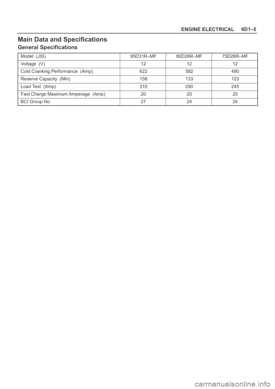
Main Data and Specifications
General Specifications
Model (JIS)95D31R–MF80D26R–MF75D26R–MF
Voltage (V)121212
Cold Cranking Performance (Amp)622582490
Reserve Capacity (Min)159133123
Load Test (Amp)310290245
Fast Charge Maximum Amperage (Amp)202020
BCI Group No.272424
Page 4625 of 6000

6D1–6
ENGINE ELECTRICAL
MEMO
Page 4629 of 6000
6D2–4
IGNITION SYSTEM
Spark Plug
Removal
1. Remove spark plugs.
Inspection and Repair
The spark plug affects entire engine performance and
therefore its inspection is very important.
Check electrode and insulator for presence of cracks,
and replace if any.
Check electrode for wear, and replace if necessary.
Check gasket for damage, and replace if necessary.
Measure insulation resistance with an ohmmeter, and
replace if faulty.
Adjust spark plug gap to 1.0 mm (0.04 in) 1.1 mm
(0.043 in).
Check fuel and electrical systems if spark plug is
extremely dirty.
Use spark plugs having low heat value (hot type plug)
if fuel and electrical systems are normal.
Use spark plugs having high heat value (cold type
plug) if insulator and electrode are extremely burned.
Sooty Spark Plugs
Much deposit of carbon or oil on the electrode and
insulator of spark plug reduces the engine performance.
Possible causes:
Too rich mixture
Presence of oil in combustion chamber
Incorrectly adjusted spark plug gap
Burning Electrodes
This fault is characterized by scorched or heavily oxidized
electrode or blistered insulator nose.
Possible causes:
Too lean mixture
Improper heat value
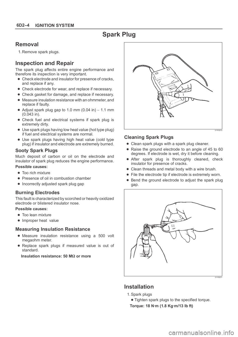
Measuring Insulation Resistance
Measure insulation resistance using a 500 volt
megaohm meter.
Replace spark plugs if measured value is out of
standard.
Insulation resistance: 50 M
or more
011RS010
Cleaning Spark Plugs
Clean spark plugs with a spark plug cleaner.
Raise the ground electrode to an angle of 45 to 60
degrees. If electrode is wet, dry it before cleaning.
After spark plug is thoroughly cleaned, check
insulator for presence of cracks.
Clean threads and metal body with a wire brush.
File the electrode tip if electrode is extremely worn.
Bend the ground electrode to adjust the spark plug
gap.
011RS011
Installation
1. Spark plugs
Tighten spark plugs to the specified torque.
Torque: 18 Nꞏm (1.8 Kgꞏm/13 lb ft)
Page 4650 of 6000
6D3–19 STARTING AND CHARGING SYSTEM
Generator
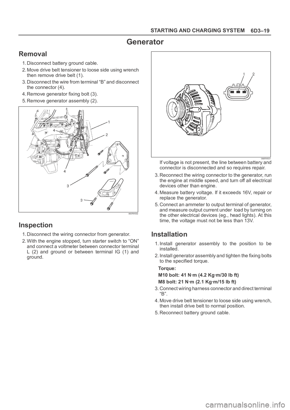
Removal
1. Disconnect battery ground cable.
2. Move drive belt tensioner to loose side using wrench
then remove drive belt (1).
3. Disconnect the wire from terminal “B” and disconnect
the connector (4).
4. Remove generator fixing bolt (3).
5. Remove generator assembly (2).
060RW002
Inspection
1. Disconnect the wiring connector from generator.
2. With the engine stopped, turn starter switch to “ON”
and connect a voltmeter between connector terminal
L (2) and ground or between terminal IG (1) and
ground.
066RW001If voltage is not present, the line between battery and
connector is disconnected and so requires repair.
3. Reconnect the wiring connector to the generator, run
the engine at middle speed, and turn off all electrical
devices other than engine.
4. Measure battery voltage. If it exceeds 16V, repair or
replace the generator.
5. Connect an ammeter to output terminal of generator,
and measure output current under load by turning on
the other electrical devices (eg., head lights). At this
time, the voltage must not be less than 13V.
Installation
1. Install generator assembly to the position to be
installed.
2. Install generator assembly and tighten the fixing bolts
to the specified torque.
To r q u e :
M10 bolt: 41 Nꞏm (4.2 Kgꞏm/30 lb ft)
M8 bolt: 21 Nꞏm (2.1 Kgꞏm/15 lb ft)
3. Connect wiring harness connector and direct terminal
“B”.
4. Move drive belt tensioner to loose side using wrench,
then install drive belt to normal position.
5. Reconnect battery ground cable.
Page 4658 of 6000
6E–1 ENGINE DRIVEABILITY AND EMISSIONS
ENGINE
ENGINE DRIVEABILITY AND EMISSIONS
CONTENTS
Specifications 6E–5. . . . . . . . . . . . . . . . . . . . . . . . .
Tightening Specifications 6E–5. . . . . . . . . . . . . . .
Vehicle Type Specifications 6E–5. . . . . . . . . . . . .
Diagrams and Schematics 6E–6. . . . . . . . . . . . . . . .
PCM Wiring Diagram (1 of 11) 6E–6. . . . . . . . . . .
PCM Wiring Diagram (2 of 11) For EC,
THAILAND, SOUTH EAST ASIA, LATIN
AMERICA, GULF, SAUDI, CHINA. 6E–7. . . . . .
PCM Wiring Diagram (3 of 11) For SOUTH
AFRICA and EXP. 6E–8. . . . . . . . . . . . . . . . . . . . .
PCM Wiring Diagram (4 of 11) 6E–9. . . . . . . . . . .
PCM Wiring Diagram (5 of 11) 6E–10. . . . . . . . . . .
PCM Wiring Diagram (6 of 11) For
AUSTRALIA, THAILAND, SOUTH EAST
ASIA, LATIN AMERICA, GULF, SAUDI,
LATIN AMERICA. 6E–11. . . . . . . . . . . . . . . . . . . . .
PCM Wiring Diagram (7 of 11) For EC. 6E–12. . .
PCM Wiring Diagram (8 of 11) For EXPORT
and SOUTH AFRICA. 6E–13. . . . . . . . . . . . . . . . .
PCM Wiring Diagram (9 of 11) Except EXP
and SOUTH AFRICA 6E–14. . . . . . . . . . . . . . . . . .
PCM Wiring Diagram (10 of 11) For
EXPORT and SOUTH AFRICA 6E–15. . . . . . . . .
PCM Wiring Diagram (11 of 11) 6E–16. . . . . . . . . .
PCM Pinouts 6E–17. . . . . . . . . . . . . . . . . . . . . . . . . . .
PCM Pinout Table, 32-Way Red
Connector – Row “A” 6E–17. . . . . . . . . . . . . . . . . .
PCM Pinout Table, 32-Way Red
Connector – Row “B” 6E–19. . . . . . . . . . . . . . . . . .
PCM Pinout Table, 32-Way White
Connector – Row “C” (For EC) 6E–20. . . . . . . . . .
PCM Pinout Table, 32-Way White
Connector – Row “C” (For except EC) 6E–21. . .
PCM Pinout Table, 32-Way White
Connector – Row “D”
(For except EXPORT and SOUTH
AFRICA) 6E–22. . . . . . . . . . . . . . . . . . . . . . . . . . . . .
PCM Pinout Table, 32-Way White
Connector – Row “D”
(For EXPORT and SOUTH AFRICA) 6E–23. . . . .
PCM Pinout Table, 32-Way Blue
Connector – Row “E”
(For except EXPORT and SOUTH
AFRICA) 6E–24. . . . . . . . . . . . . . . . . . . . . . . . . . . . .
PCM Pinout Table, 32-Way Blue
Connector – Row “E”
(For EXPORT and SOUTH AFRICA) 6E–26. . . . .
PCM Pinout Table, 32-Way Blue
Connector – Row “F” 6E–27. . . . . . . . . . . . . . . . . .
Component Locators 6E–28. . . . . . . . . . . . . . . . . . . .
Engine Component Locator (This illustration
is based on RHD model.) 6E–28. . . . . . . . . . . . . . Engine Component Locator Table 6E–29. . . . . . . .
Engine Component Locator Table 6E–31. . . . . . . .
Undercarriage Component Locator 6E–32. . . . . .
Undercarriage Component Locator Table
(Automatic Transmission) 6E–32. . . . . . . . . . . . . .
Undercarriage Component Locator Table
(Manual Transmission) 6E–33. . . . . . . . . . . . . . . .
Fuse and Relay Panel (Underhood
Electrical Center) 6E–33. . . . . . . . . . . . . . . . . . . . .
Sensors and Miscellaneous Component
Locators 6E–34. . . . . . . . . . . . . . . . . . . . . . . . . . . . .
Diagnosis 6E–37. . . . . . . . . . . . . . . . . . . . . . . . . . . . . .
Strategy-Based Diagnostics 6E–37. . . . . . . . . . . . .
Strategy-Based Diagnostics 6E–37. . . . . . . . . . . . .
DTC Stored 6E–37
. . . . . . . . . . . . . . . . . . . . . . . . . . .
No DTC 6E–37. . . . . . . . . . . . . . . . . . . . . . . . . . . . . .
No Matching Symptom 6E–37. . . . . . . . . . . . . . . . .
Intermittents 6E–37. . . . . . . . . . . . . . . . . . . . . . . . . .
No Trouble Found 6E–37. . . . . . . . . . . . . . . . . . . . .
Verifying Vehicle Repair 6E–37. . . . . . . . . . . . . . . .
General Service Information 6E–38. . . . . . . . . . . . . .
OBD Serviceablity Issues 6E–38. . . . . . . . . . . . . . .
Maintenance Schedule 6E–38. . . . . . . . . . . . . . . . .
Visual / Physical Engine Compartment
Inspection 6E–38. . . . . . . . . . . . . . . . . . . . . . . . . . . .
Basic Knowledge of Tools Required 6E–38. . . . . .
Serial Data Communications 6E–38. . . . . . . . . . . . . .
Class II Serial Data Communications 6E–38. . . . .
On-Board Diagnostic (OBD) 6E–39. . . . . . . . . . . . . .
On-Board Diagnostic Tests 6E–39. . . . . . . . . . . . .
Comprehensive Component Monitor
Diagnostic Operation 6E–39. . . . . . . . . . . . . . . . . .
Common OBD Terms 6E–40. . . . . . . . . . . . . . . . . .
The Diagnostic Executive 6E–40. . . . . . . . . . . . . . .
DTC Types 6E–41. . . . . . . . . . . . . . . . . . . . . . . . . . .
Verifying Vehicle Repair 6E–42. . . . . . . . . . . . . . . .
Reading Diagnostic Trouble Codes Using
A Tech 2 6E–42. . . . . . . . . . . . . . . . . . . . . . . . . . . . .
Tech 2 Tech 2 6E–43. . . . . . . . . . . . . . . . . . . . . . . . .
Tech 2 Features 6E–43. . . . . . . . . . . . . . . . . . . . . . .
Getting Started 6E–44. . . . . . . . . . . . . . . . . . . . . . . .
Operating Procedure (For Example) 6E–44. . . . .
DTC Modes 6E–45. . . . . . . . . . . . . . . . . . . . . . . . . . .
DTC Information Mode 6E–46. . . . . . . . . . . . . . . . .
Injector Balance Test 6E–46. . . . . . . . . . . . . . . . . . .
EGR Control Test 6E–47. . . . . . . . . . . . . . . . . . . . . .
Idle Air Control System Test 6E–48. . . . . . . . . . . . .
Page 4659 of 6000
6E–2
ENGINE DRIVEABILITY AND EMISSIONS
Primary System-Based Diagnostic 6E–50. . . . . . . . .
Primary System-Based Diagnostic 6E–50. . . . . . .
Fuel Control Heated Oxygen Sensor 6E–50. . . . .
HO2S Heater 6E–50. . . . . . . . . . . . . . . . . . . . . . . . .
Fuel Trim System Monitor Diagnostic
Operation 6E–50. . . . . . . . . . . . . . . . . . . . . . . . . . . . . .
Fuel Trim System Monitor Diagnostic
Operation 6E–50. . . . . . . . . . . . . . . . . . . . . . . . . . . .
Fuel Trim Cell Diagnostic Weights 6E–50. . . . . . .
On-Board Diagnostic (OBD) System Check 6E–51.
A/C Clutch Control Circuit Diagnosis 6E–54. . . . . . .
Electronic Ignition System Diagnosis 6E–60. . . . . . .
Fuel Metering System Check 6E–60. . . . . . . . . . . . .
Idle Air Control (IAC) Valve 6E–60. . . . . . . . . . . . . . .
Fuel System Pressure Test 6E–60. . . . . . . . . . . . . . .
Fuel Injector Coil Test Procedure and Fuel
Injector Balance Test Procedure 6E–60. . . . . . . . . .
Knock Sensor Diagnosis 6E–65. . . . . . . . . . . . . . . . .
Powertrain Control Module (PCM) Diagnosis 6E–65
Multiple PCM Information Sensor DTCS Set 6E–65
Exhaust Gas Recirculation (EGR) Diagnosis
(For except EXPORT and
SOUTH AFRICA) 6E–68. . . . . . . . . . . . . . . . . . . . . . .
Engine Tech 2 Data Definitions and Ranges 6E–68
Typical Scan Data Values 6E–70. . . . . . . . . . . . . . . .
No Malfunction Indicator Lamp (MIL) 6E–74. . . . . . .
Malfunction Indicator Lamp (MIL) “ON”
Steady 6E–77. . . . . . . . . . . . . . . . . . . . . . . . . . . . . . . .
Engine Cranks But Will Not Run 6E–79. . . . . . . . . . .
Fuel System Electrical Test 6E–85. . . . . . . . . . . . . . .
Fuel System Diagnosis 6E–88. . . . . . . . . . . . . . . . . . .
Idle Air Control (IAC) System Check 6E–93. . . . . . .
Knock Sensor (KS) System Check
(Engine Knock, Poor Performance, or Poor
Economy) 6E–95. . . . . . . . . . . . . . . . . . . . . . . . . . . . .
Exhaust Gas Recirculation (EGR) System
Check 6E–97. . . . . . . . . . . . . . . . . . . . . . . . . . . . . . . . .
Manifold Absolute Pressure (MAP) Output
Check 6E–99. . . . . . . . . . . . . . . . . . . . . . . . . . . . . . . . .
PCM Diagnostic Trouble Codes 6E–101. . . . . . . . . . .
Diagnostic Trouble Code (DTC) P0101
MAF System Performance 6E–104. . . . . . . . . . . . . . .
Diagnostic Trouble Code (DTC) P0102
MAF Sensor Circuit Low Frequency 6E–107. . . . . .
Diagnostic Trouble Code (DTC) P0103
MAF Sensor Circuit High Frequency 6E–110. . . . . .
Diagnostic Trouble Code (DTC) P0107
MAP Sensor Circuit Low Voltage 6E–112. . . . . . . . . .
Diagnostic Trouble Code (DTC) P0108
MAP Sensor Circuit High Voltage 6E–115. . . . . . . . .
Diagnostic Trouble Code (DTC) P0112
IAT Sensor Circuit Low Voltage 6E–118. . . . . . . . . . .
Diagnostic Trouble Code (DTC) P0113
IAT Sensor Circuit High Voltage 6E–121. . . . . . . . . . Diagnostic Trouble Code (DTC) P0117
ECT Sensor Circuit Low Voltage 6E–124. . . . . . . . . .
Diagnostic Trouble Code (DTC) P0118
ECT Sensor Circuit High Voltage 6E–127. . . . . . . . .
Diagnostic Trouble Code (DTC) P0121
TP System Performance 6E–130. . . . . . . . . . . . . . . . .
Diagnostic Trouble Code (DTC) P0122
TP Sensor Circuit Low Voltage 6E–133. . . . . . . . . . .
Diagnostic Trouble Code (DTC) P0123
TP Sensor Circuit High Voltage 6E–136. . . . . . . . . .
Diagnostic Trouble Code (DTC) P0131
HO2S Circuit Low Voltage Bank 1
Sensor 1 6E–139. . . . . . . . . . . . . . . . . . . . . . . . . . . . . . .
Diagnostic Trouble Code (DTC) P0132
HO2S Circuit High Voltage Bank 1
Sensor 1 6E–142. . . . . . . . . . . . . . . . . . . . . . . . . . . . . . .
Diagnostic Trouble Code (DTC) P0134
HO2S Circuit Insufficient Activity Bank 1
Sensor 1 6E–145. . . . . . . . . . . . . . . . . . . . . . . . . . . . . .
Diagnostic Trouble Code (DTC) P0151
HO2S Circuit Low Voltage Bank 2
Sensor 1 6E–148. . . . . . . . . . . . . . . . . . . . . . . . . . . . . . .
Diagnostic Trouble Code (DTC) P0152
HO2S Circuit HIGH Voltage Bank 2
Sensor 1 6E–151. . . . . . . . . . . . . . . . . . . . . . . . . . . . . . .
Diagnostic Trouble Code (DTC) P0171
Fuel Trim System Lean Bank 1 6E–154. . . . . . . . . . .
Diagnostic Trouble Code (DTC) P0172
Fuel Trim System Rich Bank 1 6E–158. . . . . . . . . . .
Diagnostic Trouble Code (DTC) P0174
Fuel Trim System Lean Bank 2 6E–162. . . . . . . . . . .
Diagnostic Trouble Code (DTC) P0175
Fuel Trim System Rich Bank 2 6E–166. . . . . . . . . . .
Diagnostic Trouble Code (DTC) P0201
Injector 1 Control Circuit 6E–170. . . . . . . . . . . . . . . . .
Diagnostic Trouble Code (DTC) P0202
Injector 2 Control Circuit 6E–173. . . . . . . . . . . . . . . . .
Diagnostic Trouble Code (DTC) P0203
Injector 3 Control Circuit 6E–176. . . . . . . . . . . . . . . . .
Diagnostic Trouble Code (DTC) P0204
Injector 4 Control Circuit 6E–179. . . . . . . . . . . . . . . . .
Diagnostic Trouble Code (DTC) P0205
Injector 5 Control Circuit 6E–182. . . . . . . . . . . . . . . . .
Diagnostic Trouble Code (DTC) P0206
Injector 6 Control Circuit 6E–185. . . . . . . . . . . . . . . . .
Diagnostic Trouble Code (DTC) P0325
KS Module Circuit 6E–188. . . . . . . . . . . . . . . . . . . . . .
Diagnostic Trouble Code (DTC) P0327
KS Sensor Circuit 6E–190. . . . . . . . . . . . . . . . . . . . . . .
Diagnostic Trouble Code (DTC) P0336
58X Reference Signal Circuit 6E–193. . . . . . . . . . . . .
Diagnostic Trouble Code (DTC) P0337
CKP Sensor Circuit Low Frequency 6E–195. . . . . . .
Diagnostic Trouble Code (DTC) P0341
CMP Sensor Circuit Performance 6E–198. . . . . . . . .
Diagnostic Trouble Code (DTC) P0342
CMP Sensor Circuit Low 6E–202. . . . . . . . . . . . . . . . .