Page 3418 of 6000

EXTERIOR/INTERIOR TRIM8J–39
Power Window System
General Description
The circuit consists of the starter switch, (door lock &)
power window switch for each of the front windows,
p o w e r w i n d o w s w i t c h f o r r e a r w i n d o w s a n d p o w e r w i n d o w
motors.
When the starter switch is turned on, the battery voltage is
applied to each of the power window switches through the
circuit breaker and the power window relay on the circuit.
The “Down” switch of the driver’s power window switch
has a built-in function which can be operated by just
touching it.
Accordingly, the window will roll down automatically by
just setting the switch to the “AUTO” position.
When the driver’s power lock switch at the driver side is
depressed, the power source to the passenger’s power
window switches are shut off. So, even if these switches
are operated, the power window motor will not operate.
Power Window Switch Removal and
Installation
Driver Seat Side
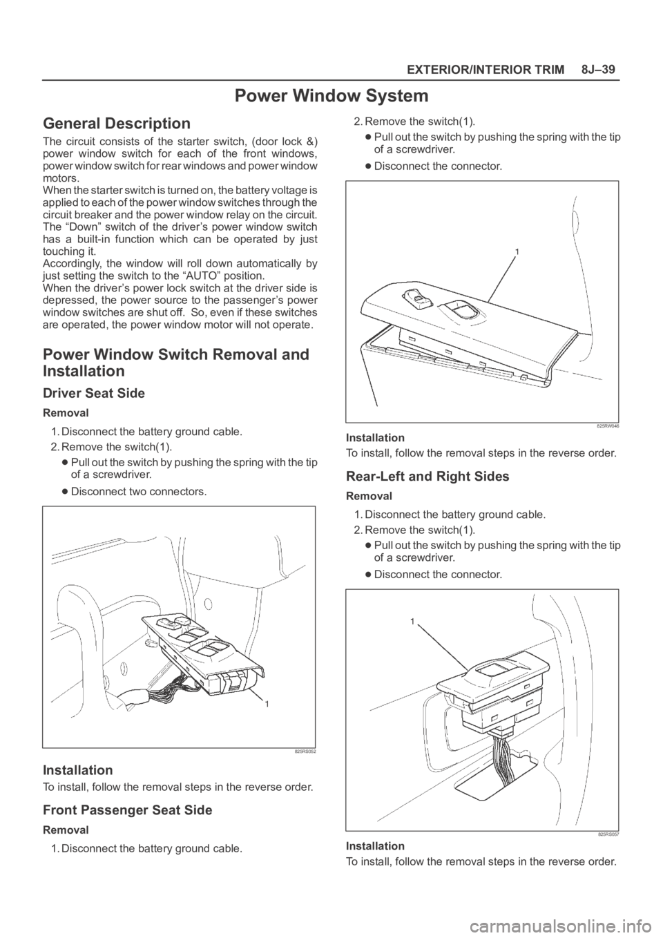
Removal
1. Disconnect the battery ground cable.
2. Remove the switch(1).
Pull out the switch by pushing the spring with the tip
of a screwdriver.
Disconnect two connectors.
825RS052
Installation
To install, follow the removal steps in the reverse order.
Front Passenger Seat Side
Removal
1. Disconnect the battery ground cable.2. Remove the switch(1).
Pull out the switch by pushing the spring with the tip
of a screwdriver.
Disconnect the connector.
825RW046
Installation
To install, follow the removal steps in the reverse order.
Rear-Left and Right Sides
Removal
1. Disconnect the battery ground cable.
2. Remove the switch(1).
Pull out the switch by pushing the spring with the tip
of a screwdriver.
Disconnect the connector.
825RS057
Installation
To install, follow the removal steps in the reverse order.
Page 3441 of 6000

SUPPLEMENTAL RESTRAINT SYSTEM 9J–4
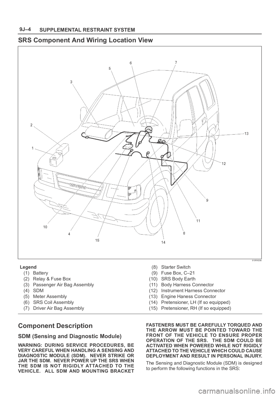
SRS Component And Wiring Location View
810RW298
Legend
(1) Battery
(2) Relay & Fuse Box
(3) Passenger Air Bag Assembly
(4) SDM
(5) Meter Assembly
(6) SRS Coil Assembly
(7) Driver Air Bag Assembly(8) Starter Switch
(9) Fuse Box, C–21
(10) SRS Body Earth
(11) Body Harness Connector
(12) Instrument Harness Connector
(13) Engine Haness Connector
(14) Pretensioner, LH (If so equipped)
(15) Pretensioner, RH (If so equipped)
Component Description
SDM (Sensing and Diagnostic Module)
WARNING: DURING SERVICE PROCEDURES, BE
VERY CAREFUL WHEN HANDLING A SENSING AND
DIAGNOSTIC MODULE (SDM). NEVER STRIKE OR
JAR THE SDM. NEVER POWER UP THE SRS WHEN
THE SDM IS NOT RIGIDLY ATTACHED TO THE
VEHICLE. ALL SDM AND MOUNTING BRACKETFASTENERS MUST BE CAREFULLY TORQUED AND
THE ARROW MUST BE POINTED TOWARD THE
FRONT OF THE VEHICLE TO ENSURE PROPER
OPERATION OF THE SRS. THE SDM COULD BE
ACTIVATED WHEN POWERED WHILE NOT RIGIDLY
ATTACHED TO THE VEHICLE WHICH COULD CAUSE
DEPLOYMENT AND RESULT IN PERSONAL INJURY.
The Sensing and Diagnostic Module (SDM) is designed
to perform the following functions in the SRS:
Page 3691 of 6000
B-5
BLOWER
MOTOR2
B-5
1
I-51
3I-51
I-51I-51
MAX HI
RELAY POWER
TRANSISTORI-50
I-50
4
H-202
H-26
10
1
3
H-20
121 2L/B
0.5P/G
12
I-32
16 I-32
P-2
0.85W/G5W
5W 0.5R/W
0.3B0.5R/W 0.3R/W
TAIL RELAY(4) ILLUMINATION
CONTROLLER0.5G/R 0.85G/R
1.25B
1.25B1.25B
0.5B
9 I-32 5W 3W
BATT
FL-1
80A
MAIN4B-36
33L/R
C-19 25A
BLOWERC-20 10A
AIR CON
3L 2L/B
0.3BR
0.5BR0.3BR 2/B 0.3GR
0.3GR/L0.5L/B
2/B
B-36
20
H-27 2
B-36H-14
1
B-36HEATER & A/C RELAY
STARTER RELAY(1)
H-141
H-1310
I-328
H-269
10 C-16
10A CLOCK ROOM
BODY-RHBODY-LH
B-18
B-19
B-1
AUTO A/C CONTROL UNITAUTO A/C CONTROL UNIT
I-3217
14 35 2112 337
I-32
22
29 6I-331 H-20
14
H-16
M
192B
I-33
2I-50
D08RY00118
Page 3692 of 6000
E-19
A/C TEHRMO
RELAY
THERMO
UNITPRESSURE
SW
I-3214I-334I-3318I-3211
AUTO A/C CONTROL UNIT
H-1616
H-241
H-611
H-1617
H-416
0.5P/G 0.5Y/B 0.5Y/B
0.5P/G
0.5G/O
1.25B
0.5G/O
0.5G/B
0.5G/B
0.5BR/Y 0.5BR/Y 0.5BR/Y 0.3G/B
0.5L/O
0.5L/W
0.3L/R
0.3L/Y
0.3BR/B0.5B 1.25B0.5G/B0.5G/W 0.5G/W 0.5G/W 0.5BR0.5LG 0.5BR
0.5BR 0.5RB
0.5BR
0.5BR
0.5BR
0.5BR
0.3B/L 0.3B/L PCM(E15)
PCM(B14)
X - 5
4X - 5
1
X -53 12
H-167
H-2413
X - 52A/C COMPRESSOR
RELAY
MAGNETIC
CLUTCHINTAKE
ACTUATOR
X - 7
4X -7
3
X -71X - 72
H-417
H-69
E-31
1
2 C-25
C-25
H-411
H-51
4
H-51
I-493
I-494 612
M
INCAR
SENSOR
I-341I-344
M
I-495
I-49I-49I-49
2I-34
3I-34
I-3312I-3313I-331I-3314
10 17 18 19 34 13 31 7
H-415
D08RY00293
Page 3695 of 6000
0.5R/G
ILLUMINATION
CONTROLLER
12
I-32
157
I-32
16 I-3229
P-2
0.85W/R5W
3L 2L/B 2L/BBATT.
5W 0.5R/W
0.3B0.5R/W 0.3R/W
TAIL REAY(4) 0.5G/R 0.85R/W
1.25B
1.25B
0.5B
9 I-3236 5W 3W FL-1
80A
MAIN4
B-36
33L/RC-20 10A
AIR CON
C-19 25A
BLOWER
BLOWER
MOTOR
B-36 2
B-36H-14
1
B-36HEATER A/C RELAY
STARTER SW (ACC)
H-141
I-328
H-265
10 C-16 10A
CLOCK ROOM
C-11 10A
AUDIO
F-12 10A
TAIL-RH
BODY-LHB-19
BODY-RHB-22BH-481.25B 15
H-2614
I-50 2
AUTO A/C CONTORL UNIT AUTO A/C CONTORL UNIT
I-32
6
H-16
0.5BR 2B 2B0.3GR/W0.5L/B
0.3BR 0.3BR
19
I-33
33
22 21 3512
H-48
0.3GR/L
MAX HI
RELAY POWER
TRANSISTOR
I-51
3
H-4811
I-51
4I-50
3
I-512I-501
H-4815
I-511
B-51
B-5
2
H-484
M
17
I-33
14
D08RY00121
Page 3696 of 6000
A/C THERMO
RELAY THERMO
SENSORPURESSURE
SW
I-3214I-334I-3318I-3211
ATUO A/C CONTROL UNIT
H-1621
H-91
H-1611
E-19
H-1619H-416
0.5P/G 0.5Y/B 0.5Y/B 0.5Y/B
0.5P/G
0.5G/O 0.5G/O
0.5G/B
0.5G/B
0.5BR/Y 0.5BR/Y 0.5BR/Y 0.3G/B
0.5L/O
0.3L/W
0.3L/R
0.3L/Y
0.3BR/B 1.25B0.3G/B0.5G/W 0.5G/W
0.5G/W0.5BR 0.5LG 0.5BR
0.5BR 0.5BR
0.5BR
0.5BR
0.5BR
0.5BR
0.3B/L 0.3B/L PCM(E15)
PCM(B14)
X - 5
4X - 5
1
X -53 12
H-1617
H-919
H-514
X - 52
A/C
COMPRESSOR
RELAY
MAGNETIC
CLUTCHINTAKE
ACTUATOR
X - 7
4X -7
3
X -71X - 72
H-417
H-69
E-31
1
2C-25
C-25
H-411
H-51
I-493
I-494612
M
IN CAR
SENSOR
I-341I-344
M
I-495
I-49I-49I-49
2I-34
3I-34
I-3312I-3313I-331I-33
31 71334
1.25B19 18 101714
H-415
D08RY00122
Page 3699 of 6000

X-2124
13X-21
X-21THERMO SW RELAY
0.5BR 0.5BR
0.5G/Y
QWS THERMO SW 0.5G/BX-21
B-19
B-18
BODY-RH
BODY-RH
I-32 I-33I-32 I-32 I-33 I-33
84
I-329I-32107111213
12
B-36 B-36
B-36 B-3634
9
H-26
5W 3W
5W
3L/R
C-16
CLOCK, ROOM
BODY ENG. FRAME10A
0.5Y/B 0.5Y/B 0.5Y/B
0.5R/G
0.5G/R 0.5G/RILLUMINATION
CONTROLLER
TAIL RELAY (4) 0.5R/W 0.3R/W0.5R/W 0.5R/W
0.5BR 0.5BR
0.5BR
HEATER
& A/C RELAY CHARGE
RELAY(1)
P-1
P-5
P-2
P-7P-10P-6
5B30B8B
8B/R
FL-1
80A MAIN
+
�ー
AUTO A/C CONTROL UNIT
I-32
H-271.25B
0.5B
20
1.25B
I-3314
I-49
4612
M
I-49 I-49 I-49
I-493
5
I-49
16
0.5L/O
0.5L/W
0.3L/R
0.3L/Y
0.3B/L
1.25B0.3B
0.5BR
C-25C-25
2 1
H-26160.5G/W 0.5LGPRESSURE SW
INTAKE
ACTUATOR
H-141
H-1310
0.85W/G 0.85W/G
5W
0.5B
0.5BR
H-167
3
H-40.5Y/B 0.5Y/B
12
H-17
1
H-24
0.5BR
3W/LFL-3
40A C/HEAT
2H-410.5G/Y
ECM(J1-23)
H-2413
5
H-41
E-23THERMO UNIT
12
I-32
3L
2L/B 2L/B
C-19 25A
BLOWER
BLOWER
MOTOR C-20 10A
A/C
I-50 2
2B 2B
0.3GR/W0.5L/B
0.3BR 0.3BR 2L/B 2B
19
I-33
33 22 34 19 18 17 12
0.3GR/LMAX HI RELAY
POWER
TRANSISTOR
I-51
3
H-26
10
I-51
4I-50
3
I-512I-501I-511
B-52
B-5
1
H-20
2
17
I-33
14 35 36 7 21
29
H-201
M
B-1
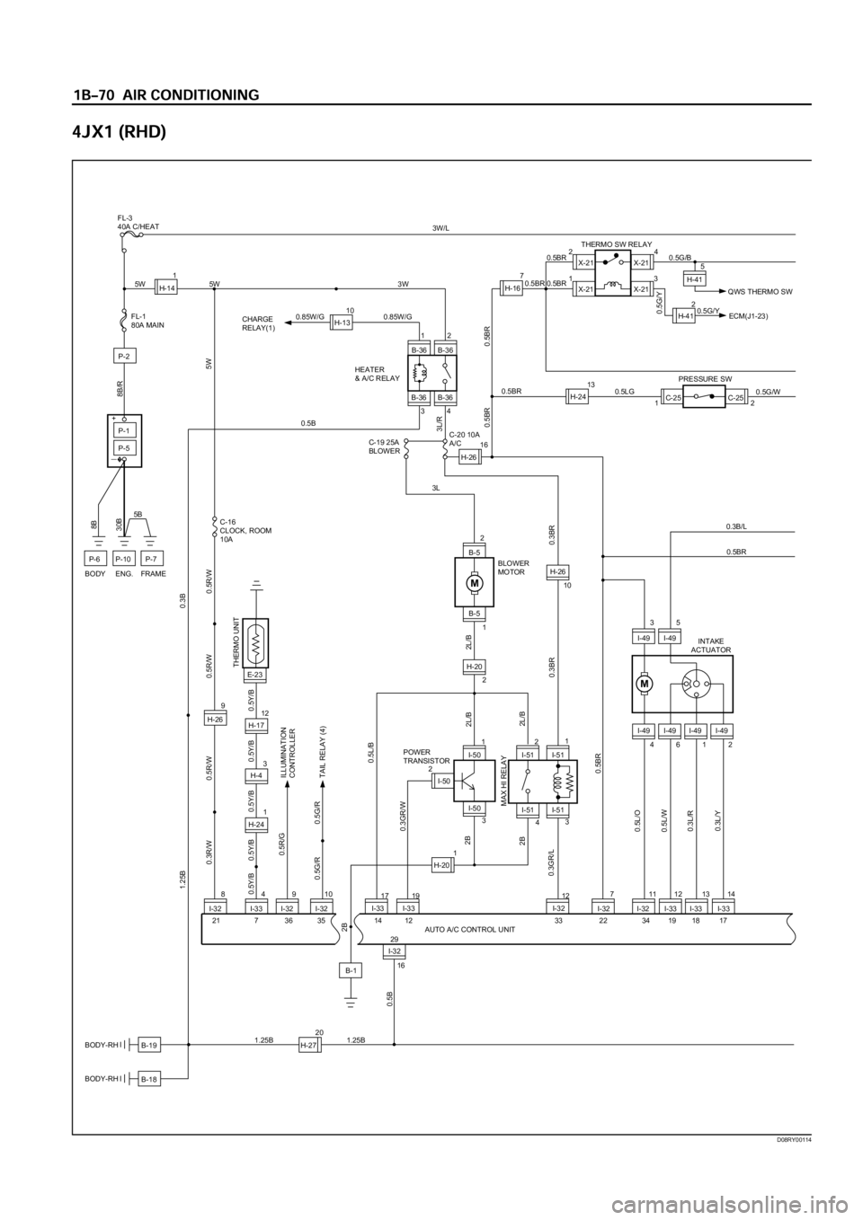
D08RY00114
Page 3700 of 6000

AUTO A/C CONTROL UNIT 0.3B/L
0.3G/W 0.3G/W
I-34
2
10 9 8 11 23 24 16 6 25 26 1 2 3 4 32 31 20 133 I-34
M
I-3414
I-34
2
1 C-86
H-24
0.3LG/B
1
2C-86
9
H-24
I-33
1 I-35
3
I-33
0.3BR/B0.5B
0.3LG/B
8I-3520.3LG/W0.3B/L
0.3B/L
20
0.3LG/W
I-33
0.3B/L
M
6
6
I-32 I-45
H-674
I-453
H-678
2
15
I-33
H-676
8
5
I-32
H-675
7
5
I-33
H-677
I-45 I-45 I-45
0.3V/W
0.3V/R
0.3V/G
0.3V 0.3V/W
0.3V/R
0.3V/G
0.3V
M
1
4 B-69
H-2511
9
45
3
H-2512
3
10
H-2618
0.3Y/BR
0.3Y/G
0.3GR
I-32 I-32I-33
0.3Y/BR
0.3Y/G
0.3GR
B-69 B-69 B-69B-69
VENT FOOT DEFB/L D/F
4
H-26
1118
I-33 I-33 1
X-1224
13X-12
X-12
X-524
13 X-5
X-5 X-5
0.5BR
11
H-410.5G/W
0.5G/O
0.5P/G
2 7
H-6H-414
H-17E-27 0.5G/O 0.5G/O
A/C THERMO
RELAY
0.5G/O ECM(J1-31)
INCAR SENSOR
AMBIENT SENSOR
SUN SENSOR
DUCT SENSOR
MIX
ACTUATORMODE
ACTUATOR
I-33
8 B-692 76 B-69 B-69 B-69
14
I-32
MAGNETIC
CLUTCH
I-401 I-40
9
H-2619
0.3GR/R
I-33
0.3GR/R
8
H-255
0.3GR/G
I-33
0.3GR/G
7
H-261
0.3GR/L
I-33
0.3GR/L
0.3GR/R
0.3B/L 0.3B/L 0.3B/L
0.3G/B0.3GR/G
0.5P/G
0.5P/G16
H-16
CERAMIC
HEATER RELAYCERAMIC
HEATER
DIODE
13
I-32
B-1 3W/L
0.5G/B
1
B-442
B-44 0.5Y/G 0.5Y/G11
H-150.3G/W
1
B-482
B-48 3W/G15
H-133W/G 2B
BODY-LH
X-12
2
6
H-16
H-1617
H-254
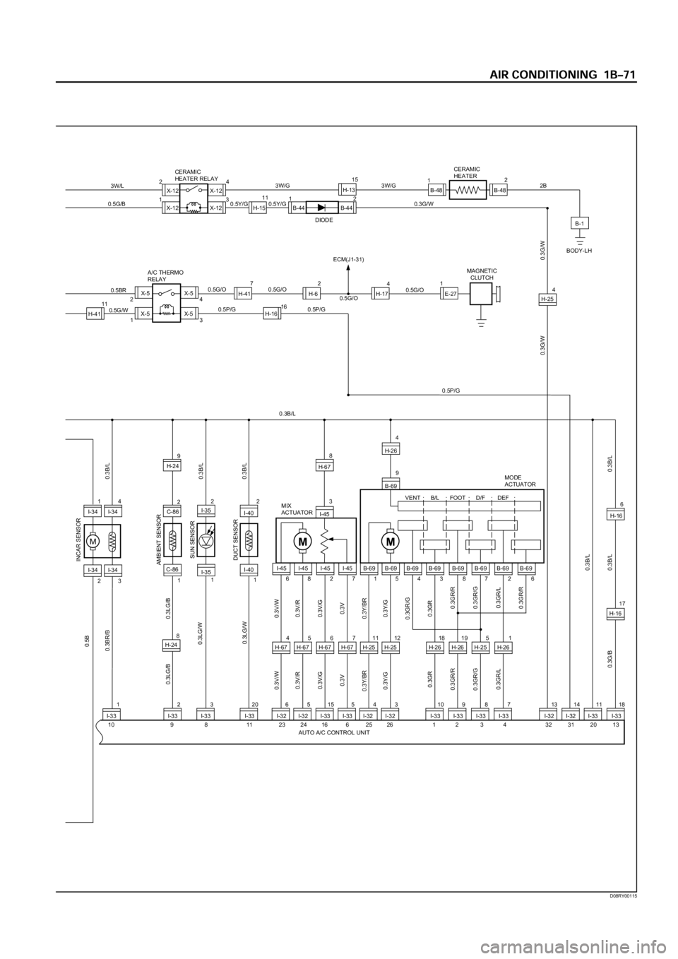
D08RY00115