1998 OPEL FRONTERA width
[x] Cancel search: widthPage 1259 of 6000
6E–142
ENGINE DRIVEABILITY AND EMISSIONS
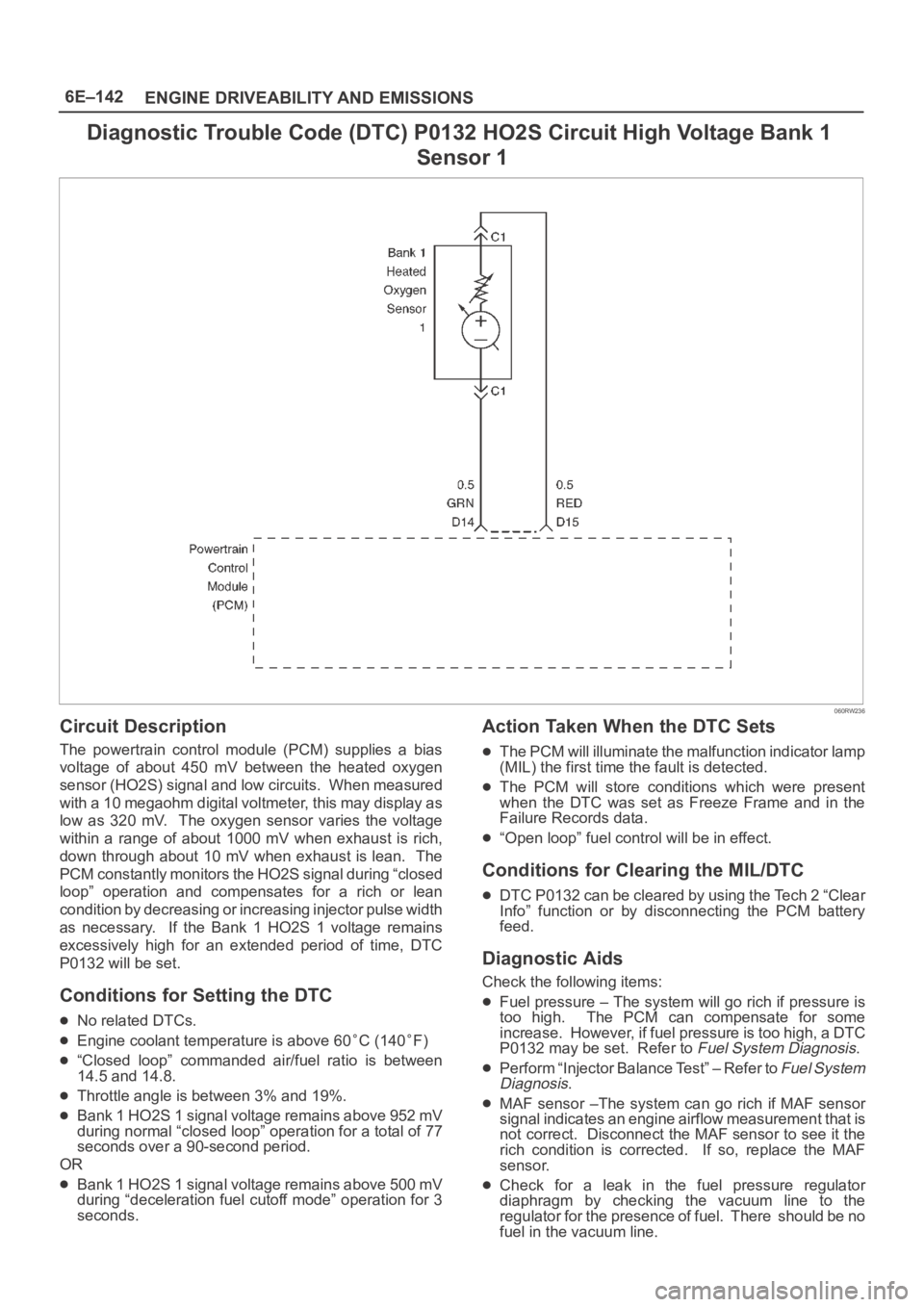
Diagnostic Trouble Code (DTC) P0132 HO2S Circuit High Voltage Bank 1
Sensor 1
060RW236
Circuit Description
The powertrain control module (PCM) supplies a bias
voltage of about 450 mV between the heated oxygen
sensor (HO2S) signal and low circuits. When measured
with a 10 megaohm digital voltmeter, this may display as
low as 320 mV. The oxygen sensor varies the voltage
within a range of about 1000 mV when exhaust is rich,
down through about 10 mV when exhaust is lean. The
PCM constantly monitors the HO2S signal during “closed
loop” operation and compensates for a rich or lean
condition by decreasing or increasing injector pulse width
as necessary. If the Bank 1 HO2S 1 voltage remains
excessively high for an extended period of time, DTC
P0132 will be set.
Conditions for Setting the DTC
No related DTCs.
Engine coolant temperature is above 60C (140F)
“Closed loop” commanded air/fuel ratio is between
14.5 and 14.8.
Throttle angle is between 3% and 19%.
Bank 1 HO2S 1 signal voltage remains above 952 mV
during normal “closed loop” operation for a total of 77
seconds over a 90-second period.
OR
Bank 1 HO2S 1 signal voltage remains above 500 mV
during “deceleration fuel cutoff mode” operation for 3
seconds.
Action Taken When the DTC Sets
The PCM will illuminate the malfunction indicator lamp
(MIL) the first time the fault is detected.
The PCM will store conditions which were present
when the DTC was set as Freeze Frame and in the
Failure Records data.
“Open loop” fuel control will be in effect.
Conditions for Clearing the MIL/DTC
DTC P0132 can be cleared by using the Tech 2 “Clear
Info” function or by disconnecting the PCM battery
feed.
Diagnostic Aids
Check the following items:
Fuel pressure – The system will go rich if pressure is
too high. The PCM can compensate for some
increase. However, if fuel pressure is too high, a DTC
P0132 may be set. Refer to
Fuel System Diagnosis.
Perform “Injector Balance Test” – Refer to Fuel System
Diagnosis.
MAF sensor –The system can go rich if MAF sensor
signal indicates an engine airflow measurement that is
not correct. Disconnect the MAF sensor to see it the
rich condition is corrected. If so, replace the MAF
sensor.
Check for a leak in the fuel pressure regulator
diaphragm by checking the vacuum line to the
regulator for the presence of fuel. There should be no
fuel in the vacuum line.
Page 1262 of 6000
6E–145 ENGINE DRIVEABILITY AND EMISSIONS
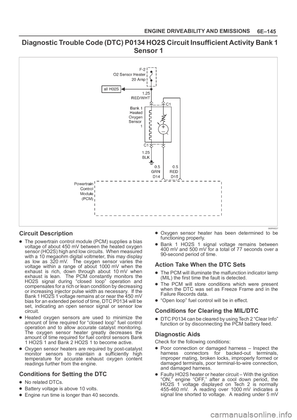
D i a g n o s t i c Tr o u b l e C o d e ( D T C ) P 0 1 3 4 H O 2 S C i r c u i t I n s u f f i c i e n t Activity Bank 1
Sensor 1
060RW237
Circuit Description
The powertrain control module (PCM) supplies a bias
voltage of about 450 mV between the heated oxygen
s e n s o r ( H O 2 S ) h i g h a n d l o w c i r c u i t s . W h e n m e a s u r e d
with a 10 megaohm digital voltmeter, this may display
as low as 320 mV. The oxygen sensor varies the
voltage within a range of about 1000 mV when the
exhaust is rich, down through about 10 mV when
exhaust is lean. The PCM constantly monitors the
HO2S signal during “closed loop” operation and
compensates for a rich or lean condition by decreasing
or increasing injector pulse width as necessary. If the
Bank 1 HO2S 1 voltage remains at or near the 450 mV
bias for an extended period of time, DTC P0134 will be
set, indicating an open sensor signal or sensor low
circuit.
Heated oxygen sensors are used to minimize the
amount of time required for “closed loop” fuel control
operation and to allow accurate catalyst monitoring.
The oxygen sensor heater greatly decreases the
amount of time required for fuel control sensors Bank
1 HO2S 1 and Bank 2 HO2S 1 to become active.
Oxygen sensor heaters are required by post-catalyst
monitor sensors to maintain a sufficiently high
temperature for accurate exhaust oxygen content
readings further from the engine.
Conditions for Setting the DTC
No related DTCs.
Battery voltage is above 10 volts.
Engine run time is longer than 40 seconds.
Oxygen sensor heater has been determined to be
functioning properly.
Bank 1 HO2S 1 signal voltage remains between
400 mV and 500 mV for a total of 77 seconds over a
90-second period of time.
Action Take When the DTC Sets
The PCM will illuminate the malfunction indicator lamp
(MIL) the first time the fault is detected.
The PCM will store conditions which were present
when the DTC was set as Freeze Frame and in the
Failure Records data.
“Open loop” fuel control will be in effect.
Conditions for Clearing the MIL/DTC
DTC P0134 can be cleared by using Tech 2 “Clear Info”
function or by disconnecting the PCM battery feed.
Diagnostic Aids
Check for the following conditions:
Poor connection or damaged harness – Inspect the
harness connectors for backed-out terminals,
improper mating, broken locks, improperly formed or
damaged terminals, poor terminal-to-wire connection,
and damaged harness.
Faulty HO2S heater or heater circuit – With the ignition
“ON,” engine “OFF,” after a cool down period, the
HO2S 1 voltage displayed on Tech 2 is normally
455-460 mV. A reading over 1000 mV indicates a
signal line shorted to voltage. A reading under 5 mV
Page 1265 of 6000
6E–148
ENGINE DRIVEABILITY AND EMISSIONS
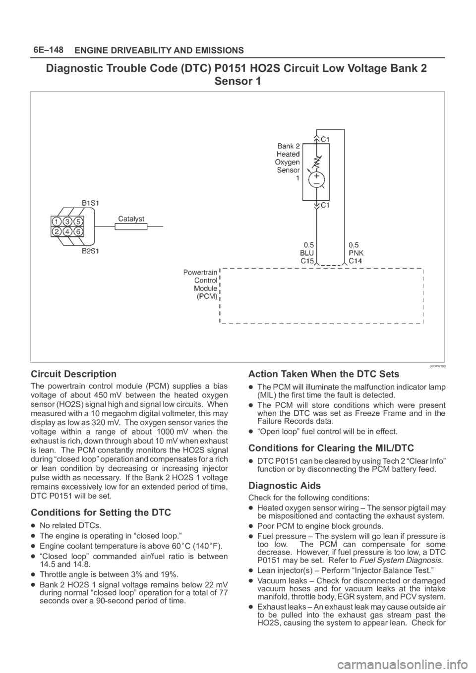
Diagnostic Trouble Code (DTC) P0151 HO2S Circuit Low Voltage Bank 2
Sensor 1
060RW190
Circuit Description
The powertrain control module (PCM) supplies a bias
voltage of about 450 mV between the heated oxygen
sensor (HO2S) signal high and signal low circuits. When
measured with a 10 megaohm digital voltmeter, this may
display as low as 320 mV. The oxygen sensor varies the
voltage within a range of about 1000 mV when the
exhaust is rich, down through about 10 mV when exhaust
is lean. The PCM constantly monitors the HO2S signal
during “closed loop” operation and compensates for a rich
or lean condition by decreasing or increasing injector
pulse width as necessary. If the Bank 2 HO2S 1 voltage
remains excessively low for an extended period of time,
DTC P0151 will be set.
Conditions for Setting the DTC
No related DTCs.
The engine is operating in “closed loop.”
Engine coolant temperature is above 60C (140F).
“Closed loop” commanded air/fuel ratio is between
14.5 and 14.8.
Throttle angle is between 3% and 19%.
Bank 2 HO2S 1 signal voltage remains below 22 mV
during normal “closed loop” operation for a total of 77
seconds over a 90-second period of time.
Action Taken When the DTC Sets
The PCM will illuminate the malfunction indicator lamp
(MIL) the first time the fault is detected.
The PCM will store conditions which were present
when the DTC was set as Freeze Frame and in the
Failure Records data.
“Open loop” fuel control will be in effect.
Conditions for Clearing the MIL/DTC
DTC P0151 can be cleared by using Tech 2 “Clear Info”
function or by disconnecting the PCM battery feed.
Diagnostic Aids
Check for the following conditions:
Heated oxygen sensor wiring – The sensor pigtail may
be mispositioned and contacting the exhaust system.
Poor PCM to engine block grounds.
Fuel pressure – The system will go lean if pressure is
too low. The PCM can compensate for some
decrease. However, if fuel pressure is too low, a DTC
P0151 may be set. Refer to
Fuel System Diagnosis.
Lean injector(s) – Perform “Injector Balance Test.”
Vacuum leaks – Check for disconnected or damaged
vacuum hoses and for vacuum leaks at the intake
manifold, throttle body, EGR system, and PCV system.
Exhaust leaks – An exhaust leak may cause outside air
to be pulled into the exhaust gas stream past the
HO2S, causing the system to appear lean. Check for
Page 1268 of 6000
6E–151 ENGINE DRIVEABILITY AND EMISSIONS
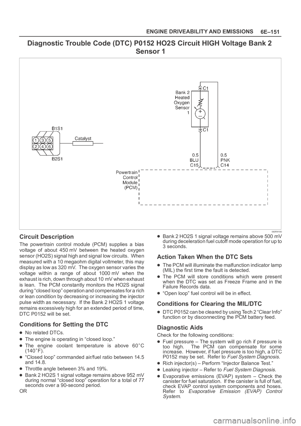
Diagnostic Trouble Code (DTC) P0152 HO2S Circuit HIGH Voltage Bank 2
Sensor 1
060RW190
Circuit Description
The powertrain control module (PCM) supplies a bias
voltage of about 450 mV between the heated oxygen
sensor (HO2S) signal high and signal low circuits. When
measured with a 10 megaohm digital voltmeter, this may
display as low as 320 mV. The oxygen sensor varies the
voltage within a range of about 1000 mV when the
exhaust is rich, down through about 10 mV when exhaust
is lean. The PCM constantly monitors the HO2S signal
during “closed loop” operation and compensates for a rich
or lean condition by decreasing or increasing the injector
pulse width as necessary. If the Bank 2 HO2S 1 voltage
remains excessively high for an extended period of time,
DTC P0152 will be set.
Conditions for Setting the DTC
No related DTCs.
The engine is operating in “closed loop.”
The engine coolant temperature is above 60C
(140
F).
“Closed loop” commanded air/fuel ratio between 14.5
and 14.8.
Throttle angle between 3% and 19%.
Bank 2 HO2S 1 signal voltage remains above 952 mV
during normal “closed loop” operation for a total of 77
seconds over a 90-second period.
OR
Bank 2 HO2S 1 signal voltage remains above 500 mV
during deceleration fuel cutoff mode operation for up to
3 seconds.
Action Taken When the DTC Sets
The PCM will illuminate the malfunction indicator lamp
(MIL) the first time the fault is detected.
The PCM will store conditions which were present
when the DTC was set as Freeze Frame and in the
Failure Records data.
“Open loop” fuel control will be in effect.
Conditions for Clearing the MIL/DTC
DTC P0152 can be cleared by using Tech 2 “Clear Info”
function or by disconnecting the PCM battery feed.
Diagnostic Aids
Check for the following conditions:
Fuel pressure – The system will go rich if pressure is
too high. The PCM can compensate for some
increase. However, if fuel pressure is too high, a DTC
P0152 may be set. Refer to
Fuel System Diagnosis.
Rich injector(s) – Perform “Injector Balance Test.”
Leaking injector – Refer to Fuel System Diagnosis.
Evaporative emissions (EVAP) system – Check the
canister for fuel saturation. If the canister is full of fuel,
check EVAP control system components and hoses.
Refer to
Evaporative Emission (EVAP) Control
System
.
Page 1453 of 6000
6E–336
ENGINE DRIVEABILITY AND EMISSIONS
0016
Electrically Erasable Programmable Read
Only Memory (EEPROM)
The electrically erasable programmable read only
memory (EEPROM) is a permanent memory chip that is
physically soldered within the PCM. The EEPROM
contains the program and the calibration information that
the PCM needs to control powertrain operation.
Unlike the PROM used in past applications, the EEPROM
is not replaceable. If the PCM is replaced, the new PCM
will need to be programmed. Equipment containing the
correct program and calibration for the vehicle is required
to program the PCM.
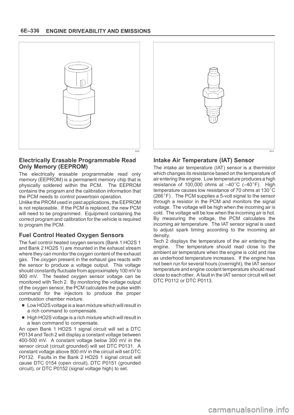
Fuel Control Heated Oxygen Sensors
The fuel control heated oxygen sensors (Bank 1 HO2S 1
and Bank 2 HO2S 1) are mounted in the exhaust stream
where they can monitor the oxygen content of the exhaust
gas. The oxygen present in the exhaust gas reacts with
the sensor to produce a voltage output. This voltage
should constantly fluctuate from approximately 100 mV to
900 mV. The heated oxygen sensor voltage can be
monitored with Tech 2. By monitoring the voltage output
of the oxygen sensor, the PCM calculates the pulse width
command for the injectors to produce the proper
combustion chamber mixture.
Low HO2S voltage is a lean mixture which will result in
a rich command to compensate.
High HO2S voltage is a rich mixture which will result in
a lean command to compensate.
An open Bank 1 HO2S 1 signal circuit will set a DTC
P0134 and Tech 2 will display a constant voltage between
400-500 mV. A constant voltage below 300 mV in the
sensor circuit (circuit grounded) will set DTC P0131. A
constant voltage above 800 mV in the circuit will set DTC
P0132. Faults in the Bank 2 HO2S 1 signal circuit will
cause DTC 0154 (open circuit), DTC P0151 (grounded
circuit), or DTC P0152 (signal voltage high) to set.
0012
Intake Air Temperature (IAT) Sensor
The intake air temperature (IAT) sensor is a thermistor
which changes its resistance based on the temperature of
air entering the engine. Low temperature produces a high
resistance of 100,000 ohms at –40
C (–40F). High
temperature causes low resistance of 70 ohms at 130
C
(266
F) . The PCM supplies a 5-volt signal to the sensor
through a resistor in the PCM and monitors the signal
voltage. The voltage will be high when the incoming air is
cold. The voltage will be low when the incoming air is hot.
By measuring the voltage, the PCM calculates the
incoming air temperature. The IAT sensor signal is used
to adjust spark timing according to the incoming air
density.
Tech 2 displays the temperature of the air entering the
engine. The temperature should read close to the
ambient air temperature when the engine is cold and rise
as underhood temperature increases. If the engine has
not been run for several hours (overnight), the IAT sensor
temperature and engine coolant temperature should read
close to each other. A fault in the IAT sensor circuit will set
DTC P0112 or DTC P0113.
Page 1739 of 6000

6A – 6 ENGINE MECHANICAL
SERVICE STANDARD
Enginemm (in)
Parts Items Service standard Service limit Remarks
Cylinder Head
Va l v e S p r i n g
Va l v e a n d
Valve guide
Camshaft0.075 (0.0030) or less
95.0 (3.740)
45.7 (1.8)
—
241 (54.2)
6.959 – 6.977
(0.27 – 0.272)
6.692 – 6.970
(0.271 – 0.272)
0.023 – 0.056
(0.0009 – 0.0022)
0.03 – 0.063
(0.0011 – 0.0024)
8.0 (0.312)
1.1 (0.0433)
1.2 (0.0472)
1.2 (0.0472)
45°
2.1 (0.0827)
2.1 (0.0827)
0.08 (0.00314)
46.67 (1.8374)
46.77 (1.8413)
29.939 – 29.960
(1.167 – 1.168)
0.02 (0.0008) or less
0.40 – 0.082
(0.0016 – 0.0032)0.50 (0.0197)
—
44.8 (1.765)
1.6 (0.063)
210 (47.22)
6.92 (0.270)
6.90 (0.269)
0.19 (0.0074)
0.20 (0.0079)
—
1.6 (0.0630)
1.1 (0.0433)
1.1 (0.0433)
—
2.6 (0.1024)
2.6 (0.1024)
2.0 (0.00797)
46.57 (1.8335)
46.67 (1.8374)
29.84 (1.1748)
0.10 (0.0039)
0.12 (0.0047)Cannot be
reground Cylinder head lower surface for flatness
Cylinder head height
Free height
Squareness
Spring tension (when assembled) N(lb)
Diameter of Valve stem IN
EX
Valve and valve guide clearance IN
EX
Valve guide upper end height
(Measured from the Cylinder head upper
face)
Valve guide margin
Valve thickness IN
EX
Valve seat contact surface angle
Valve seat contact width IN
EX
End play
Cam lobe height IN
EX
Journal diameter
Runout
Camshaft oil clearance
Page 1783 of 6000
6A – 50 ENGINE MECHANICAL
NOTE: Do not allow the camshaft to rotate.
6) Remove the camshaft bracket and measure the
plastigauge width and determine the oil
clearance. If the oil clearance exceeds the
specified limit, replace the camshaft carrier
and/or camshaft.
Oil clearance.
Standard: 0.040 – 0.082 mm (0.0016 – 0.0032 in)
Limit: 0.12 mm (0.0047 in)
7) Clean the plastigauge from the camshaft bracket
and camshaft carrier.
5. Camshaft thrust clearance.
1) Clean the camshaft, camshaft bracket and
camshaft carrier.
2) Put camshaft carrier on the cylinder head.
3) Put camshaft on the camshaft carrier.
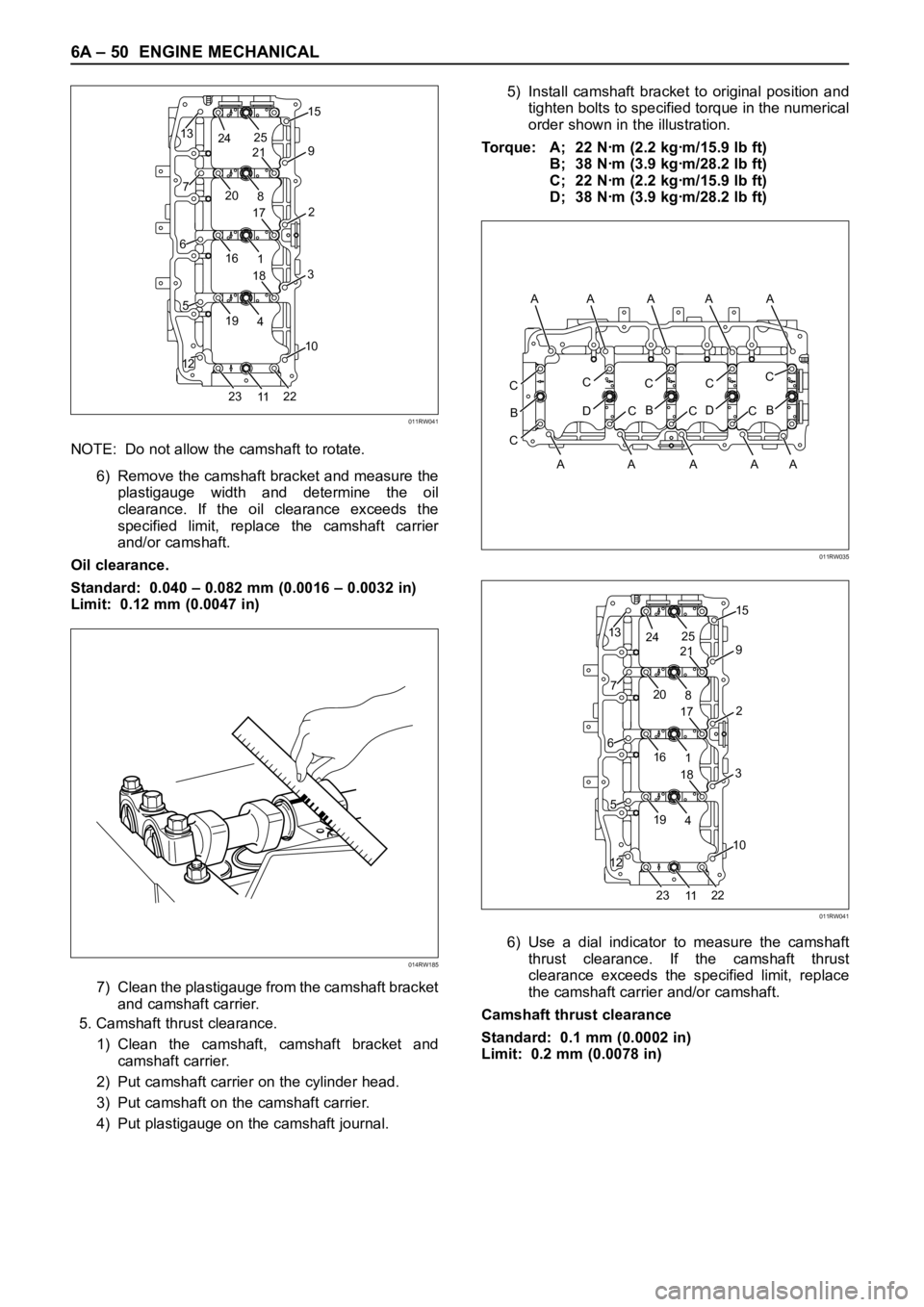
4) Put plastigauge on the camshaft journal.5) Install camshaft bracket to original position and
tighten bolts to specified torque in the numerical
order shown in the illustration.
Torque: A; 22 Nꞏm (2.2 kgꞏm/15.9 lb ft)
B; 38 Nꞏm (3.9 kgꞏm/28.2 lb ft)
C; 22 Nꞏm (2.2 kgꞏm/15.9 lb ft)
D; 38 Nꞏm (3.9 kgꞏm/28.2 lb ft)
6) Use a dial indicator to measure the camshaft
thrust clearance. If the camshaft thrust
clearance exceeds the specified limit, replace
the camshaft carrier and/or camshaft.
Camshaft thrust clearance
Standard: 0.1 mm (0.0002 in)
Limit: 0.2 mm (0.0078 in)
13
7
6
5
1215
2
3
10
9
20
8
19
2322
4
161
11 25
24
21
17
18
011RW041
014RW185
CC
D
B
CC
B
CC
D
CC
B
C
A AA A A A
AAAA
011RW035
13
7
6
5
1215
2
3
10
9
20
8
19
2322
4
161
11 25
24
21
17
18
011RW041
Page 1797 of 6000
6A – 64 ENGINE MECHANICAL
Valve Depression
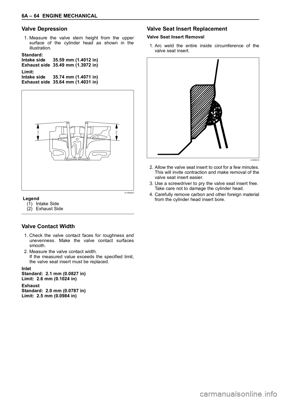
1. Measure the valve stem height from the upper
surface of the cylinder head as shown in the
illustration.
Standard:
Intake side 35.59 mm (1.4012 in)
Exhaust side 35.49 mm (1.3972 in)
Limit:
Intake side 35.74 mm (1.4071 in)
Exhaust side 35.64 mm (1.4031 in)
Legend
(1) Intake Side
(2) Exhaust Side
Valve Contact Width
1. Check the valve contact faces for roughness and
unevenness. Make the valve contact surfaces
smooth.
2. Measure the valve contact width.
If the measured value exceeds the specified limit,
the valve seat insert must be replaced.
Inlet
Standard: 2.1 mm (0.0827 in)
Limit: 2.6 mm (0.1024 in)
Exhaust
Standard: 2.0 mm (0.0787 in)
Limit: 2.5 mm (0.0984 in)
Valve Seat Insert Replacement
Valve Seat Insert Removal
1. Arc weld the entire inside circumference of the
valve seat insert.
2. Allow the valve seat insert to cool for a few minutes.
This will invite contraction and make removal of the
valve seat insert easier.
3. Use a screwdriver to pry the valve seat insert free.
Take care not to damage the cylinder head.
4. Carefully remove carbon and other foreign material
from the cylinder head insert bore.
12
011RW044
014RS015