Page 244 of 6000
I-32
C-1C-3I-33
E-3E-19B-19C-25
A 2
B-361
H-14
C-19
25A
BLOWER
MOTOR
C-20
10A
A/C FL-1
80A
MAIN
Heater
Relay
1B-3610
H-13
0.3
B 0.85
W/G0.85
W/R
3.0
W
3.0
L/R
0.5
BR
1.25
B
B-19
BODY-LH3
B-36
4B-36
BATT.(+)
Blower
MotorIntake
Actuator STARTER
RELAY(1)
0.5
LG 0.5
BR0.5
BR
0.5
G/W
0.5
P/G0.5
P/G0.5
G/O
0.5
G/O
PCM
(C3-E15)
31 13
COMP-F/B 70.5
BR
0.5
BR/Y 0.3
G/B0.5
G/B0.5
BR/Y 0.5
BR
Triple
Pressure
Switch0.5
BR
A
A/C
Thermo Relay
Auto A/C Control Unit
3X-5
16
H-1617H-16
14
I-3218I-33
1X-5
13H-24
12
H-41
2 1
C-25
C-25
4X-5X-5 2
X-57
H-16
A/C
Compressor
Relay
Magnetic
clutch
1X-7
3X-74X-72
X-7
PCM
(C-1-B14)
E-39
1
H-67
H-41
5
H-41
Engine
Coolant
Temperature
Sensor
ENGINE COOLANT
TEMPERATURE GAUGE
0.5
Y/B
0.5
Y/B
0.5
Y/B
E-1911
1
H-61
H-24
I-334
B-36X-5X-7
H-14H-16
H-24
H-13
H-6H-41
6H-41
D08RY00182
Page 250 of 6000
Temperature on the Sensor
Temperature Detector(C)
Sensor Resistance
Value(k
)
20
25
30A
U
TO
4321
-20 0 5 10 15 20
25 30
-10 0 10 20 30 40
17.09
9.93
3.75
2.24
6.0
1.6 30.69
865RX007
0
10 0 -10 -20 30 4020 5 10 15 20 25 30
Temperature on the Sensor
Temperature Detector(C)
Sensor Resistance
Value(k
)
17.09 30.69
9.93
6.0
3.75
2.24
1.6
C01RX012
– Testing rod12
A
Current
value
40A or more
+
12
21
D06RY00001
Page 443 of 6000

DIFFERENTIAL (FRONT) 4A1–6
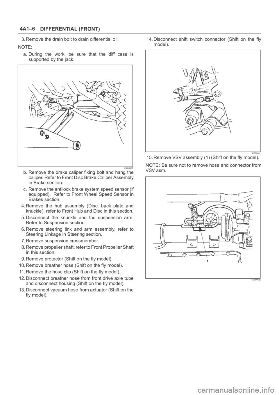
3. Remove the drain bolt to drain differential oil.
NOTE:
a. During the work, be sure that the diff case is
supported by the jack.
412RS003
b. Remove the brake caliper fixing bolt and hang the
caliper. Refer to Front Disc Brake Caliper Assembly
in Brake section.
c. Remove the antilock brake system speed sensor (if
equipped). Refer to Front Wheel Speed Sensor in
Brakes section.
4. Remove the hub assembly (Disc, back plate and
knuckle), refer to Front Hub and Disc in this section.
5. Disconnect the knuckle and the suspension arm.
Refer to Suspension section.
6. Remove steering link and arm assembly, refer to
Steering Linkage in Steering section.
7. Remove suspension crossmember.
8. Remove propeller shaft, refer to Front Propeller Shaft
in this section.
9. Remove protector (Shift on the fly model).
10. Remove breather hose (Shift on the fly model).
11. Remove the hose clip (Shift on the fly model).
12. Disconnect breather hose from front drive axle tube
and disconnect housing (Shift on the fly model).
13. Disconnect vacuum hose from actuator (Shift on the
fly model).14. Disconnect shift switch connector (Shift on the fly
model).
412RS031
15. Remove VSV assembly (1) (Shift on the fly model).
NOTE: Be sure not to remove hose and connector from
VSV asm.
412RW002
Page 471 of 6000

4A2A–4
DIFFERENTIAL (REAR 220mm)
Axle Housing
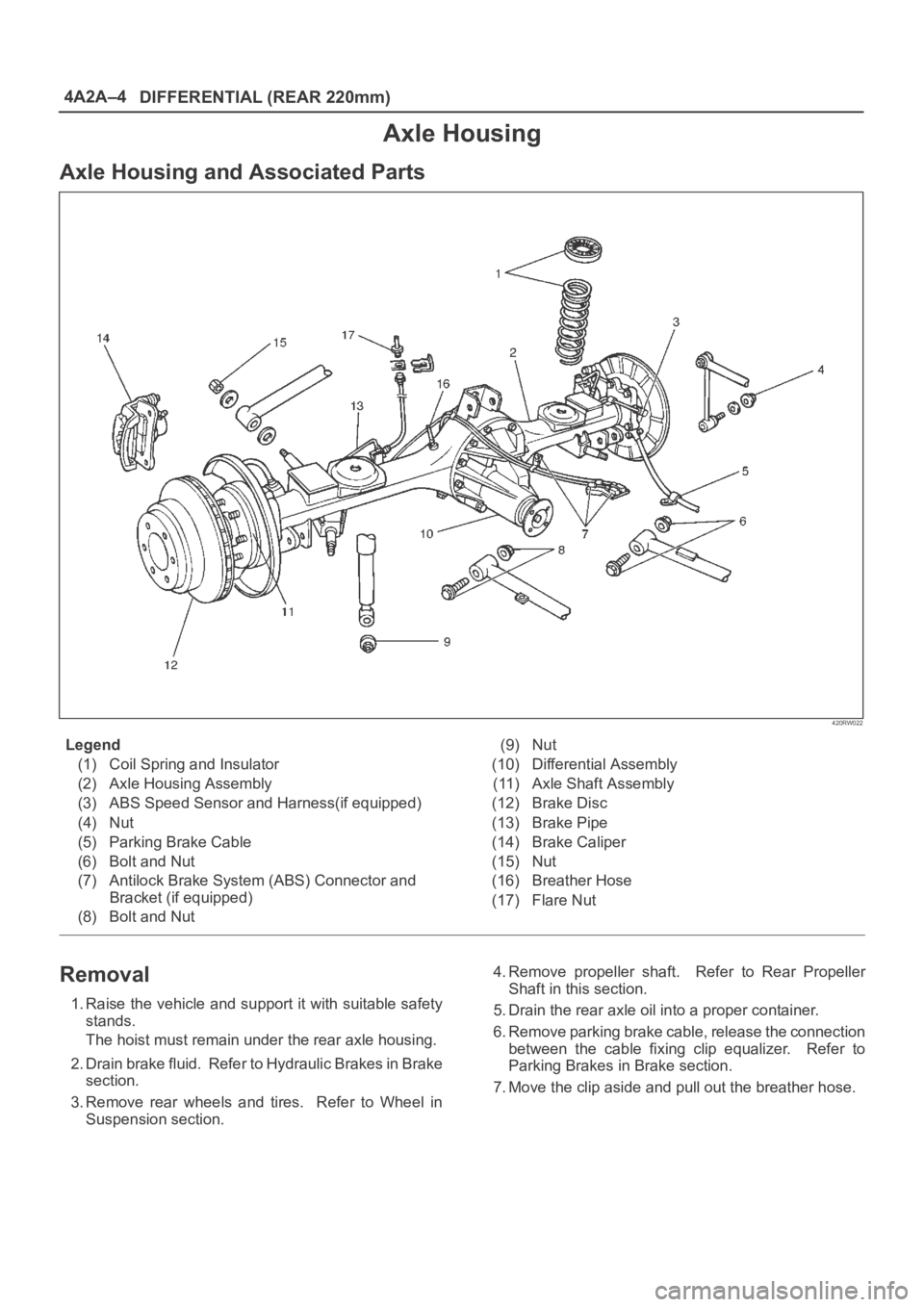
Axle Housing and Associated Parts
420RW022
Legend
(1) Coil Spring and Insulator
(2) Axle Housing Assembly
(3) ABS Speed Sensor and Harness(if equipped)
(4) Nut
(5) Parking Brake Cable
(6) Bolt and Nut
(7) Antilock Brake System (ABS) Connector and
Bracket (if equipped)
(8) Bolt and Nut(9) Nut
(10) Differential Assembly
(11) Axle Shaft Assembly
(12) Brake Disc
(13) Brake Pipe
(14) Brake Caliper
(15) Nut
(16) Breather Hose
(17) Flare Nut
Removal
1. Raise the vehicle and support it with suitable safety
stands.
The hoist must remain under the rear axle housing.
2. Drain brake fluid. Refer to Hydraulic Brakes in Brake
section.
3. Remove rear wheels and tires. Refer to Wheel in
Suspension section.4. Remove propeller shaft. Refer to Rear Propeller
Shaft in this section.
5. Drain the rear axle oil into a proper container.
6. Remove parking brake cable, release the connection
between the cable fixing clip equalizer. Refer to
Parking Brakes in Brake section.
7. Move the clip aside and pull out the breather hose.
Page 472 of 6000

DIFFERENTIAL (REAR 220mm)
4A2A–5
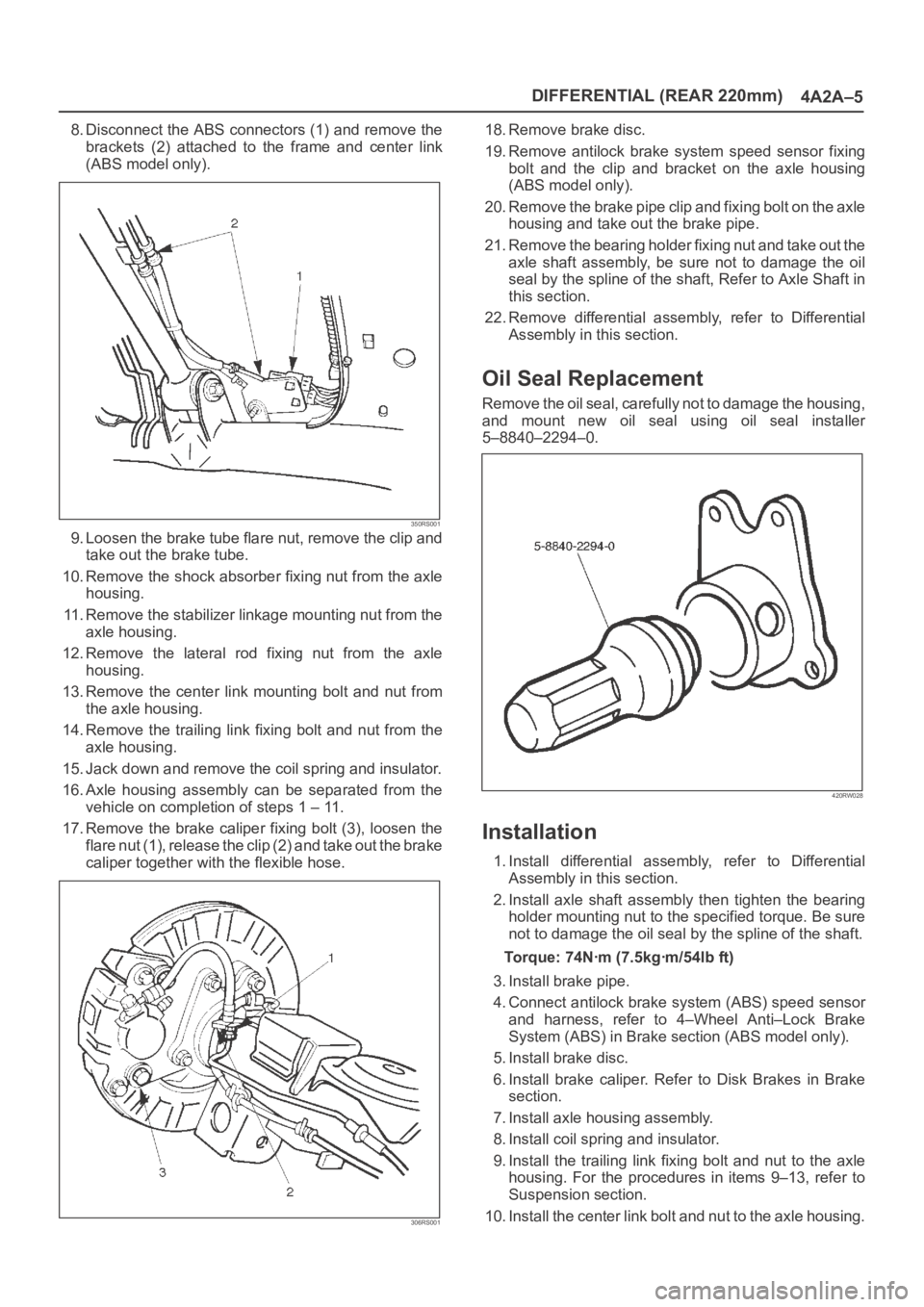
8. Disconnect the ABS connectors (1) and remove the
brackets (2) attached to the frame and center link
(ABS model only).
350RS001
9. Loosen the brake tube flare nut, remove the clip and
take out the brake tube.
10. Remove the shock absorber fixing nut from the axle
housing.
11. Remove the stabilizer linkage mounting nut from the
axle housing.
12. Remove the lateral rod fixing nut from the axle
housing.
13. Remove the center link mounting bolt and nut from
the axle housing.
14. Remove the trailing link fixing bolt and nut from the
axle housing.
15. Jack down and remove the coil spring and insulator.
16. Axle housing assembly can be separated from the
vehicle on completion of steps 1 – 11.
17. Remove the brake caliper fixing bolt (3), loosen the
flare nut (1), release the clip (2) and take out the brake
caliper together with the flexible hose.
306RS001
18. Remove brake disc.
19. Remove antilock brake system speed sensor fixing
bolt and the clip and bracket on the axle housing
(ABS model only).
20. Remove the brake pipe clip and fixing bolt on the axle
housing and take out the brake pipe.
21. Remove the bearing holder fixing nut and take out the
axle shaft assembly, be sure not to damage the oil
seal by the spline of the shaft, Refer to Axle Shaft in
this section.
22. Remove differential assembly, refer to Differential
Assembly in this section.
Oil Seal Replacement
Remove the oil seal, carefully not to damage the housing,
and mount new oil seal using oil seal installer
5–8840–2294–0.
420RW028
Installation
1. Install differential assembly, refer to Differential
Assembly in this section.
2. Install axle shaft assembly then tighten the bearing
holder mounting nut to the specified torque. Be sure
not to damage the oil seal by the spline of the shaft.
Torque: 74Nꞏm (7.5kgꞏm/54lb ft)
3. Install brake pipe.
4. Connect antilock brake system (ABS) speed sensor
and harness, refer to 4–Wheel Anti–Lock Brake
System (ABS) in Brake section (ABS model only).
5. Install brake disc.
6. Install brake caliper. Refer to Disk Brakes in Brake
section.
7. Install axle housing assembly.
8. Install coil spring and insulator.
9. Install the trailing link fixing bolt and nut to the axle
housing. For the procedures in items 9–13, refer to
Suspension section.
10. Install the center link bolt and nut to the axle housing.
Page 475 of 6000
4A2A–8
DIFFERENTIAL (REAR 220mm)
Differential Assembly
Differential Assembly and Associated Parts
425RW055
Legend
(1) Bolt and Nut
(2) Axle Shaft Assembly(3) Parking Brake Cable
(4) Differential Assembly
(5) Nut
Removal
1. Jack up and support the frame with stands.
2. Remove the wheel and tire. Refer to Wheel in
Steering section.
3. Drain the differential oil.
4. Remove the propeller shaft. Refer to Rear Propeller
Shaft in this section.
5. Remove the ABS speed sensor(ABS model only).
Refer to 4–Wheel Anti–lock Brake System (ABS) in
Brake section.6. Remove the parking brake cable fastening clip and
disconnect the equalizer section. Refer to Parking
Brakes in Brake section.
7. Remove the bearing holder fixing nuts.
8. Remove axle shaft assembly, be sure not to damage
the oil seal by axle shaft.
9. Remove differential carrier mounting bolts and nuts.
10. Remove differential assembly.
Page 507 of 6000

4A2B–4DIFFERENTIAL (REAR 244mm)
Axle Housing
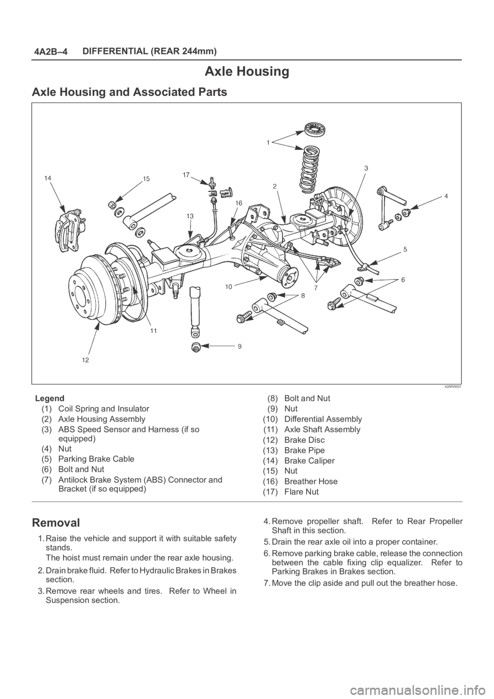
Axle Housing and Associated Parts
420RW001
Legend
(1) Coil Spring and Insulator
(2) Axle Housing Assembly
(3) ABS Speed Sensor and Harness (if so
equipped)
(4) Nut
(5) Parking Brake Cable
(6) Bolt and Nut
(7) Antilock Brake System (ABS) Connector and
Bracket (if so equipped)(8) Bolt and Nut
(9) Nut
(10) Differential Assembly
(11) Axle Shaft Assembly
(12) Brake Disc
(13) Brake Pipe
(14) Brake Caliper
(15) Nut
(16) Breather Hose
(17) Flare Nut
Removal
1. Raise the vehicle and support it with suitable safety
stands.
The hoist must remain under the rear axle housing.
2. Drain brake fluid. Refer to Hydraulic Brakes in Brakes
section.
3. Remove rear wheels and tires. Refer to Wheel in
Suspension section.4. Remove propeller shaft. Refer to Rear Propeller
Shaft in this section.
5. Drain the rear axle oil into a proper container.
6. Remove parking brake cable, release the connection
between the cable fixing clip equalizer. Refer to
Parking Brakes in Brakes section.
7. Move the clip aside and pull out the breather hose.
Page 508 of 6000

DIFFERENTIAL (REAR 244mm)
4A2B–5
8. Disconnect the ABS connectors (1) and remove the
brackets (2) (if so equipped) attached to the frame
and center link.
350RS001
9. Loosen the brake tube flare nut, remove the clip and
take out the brake tube.
10. Remove the shock absorber fixing nut from the axle
housing.
11. Remove the stabilizer linkage mounting nut from the
axle housing.
12. Remove the lateral rod fixing nut from the axle
housing.
13. Remove the center link mounting bolt and nut from
the axle housing.
14. Remove the trailing link fixing bolt and nut from the
axle housing.
15. Jack down and remove the coil spring and insulator.
16. Axle housing assembly can be separated from the
vehicle on completion of steps 1 – 11.
17. Remove the brake caliper fixing bolt (3), loosen the
flare nut (1), release the clip (2) and take out the brake
caliper together with the flexible hose.
306RS001
18. Remove brake disc.
19. Remove antilock brake system speed sensor fixing
bolt and the clip and bracket (if so equipped) on the
axle housing.
20. Remove the brake pipe clip and fixing bolt on the axle
housing and take out the brake pipe.
21. Remove the bearing holder fixing nut and take out the
axle shaft assembly, be sure not to damage the oil
seal by the spline of the shaft, Refer to Axle Shaft in
this section.
22. Remove differential assembly, refer to Differential
Assembly in this section.
Oil Seal Replacement
Remove the oil seal, carefully not to damage the housing,
and mount new oil seal using oil seal installer
5–8840–2294–0
420RW028
Installation
1. Install differential assembly, refer to Differential
Assembly in this section.
2. Install axle shaft assembly then tighten the bearing
holder mounting nut to the specified torque. Be sure
not to damage the oil seal by the spline of the shaft.
Torque: 74Nꞏm (7.5kgꞏm/54 lb ft)
3. Install brake pipe.
4. Connect antilock brake system (ABS) speed sensor
and harness (if so equipped), refer to Anti–Lock
Brake System in Brake section.
5. Install brake disc.
6. Install brake caliper. Refer to Disk Brakes in Brake
section.
7. Install axle housing assembly.
8. Install coil spring and insulator.
9. Install the trailing link fixing bolt and nut to the axle
housing. For the procedures in items 9–13, refer to
Suspension section.
10. Install the center link bolt and nut to the axle housing.