1998 OPEL FRONTERA lights
[x] Cancel search: lightsPage 3178 of 6000
METER AND GAUGE8E–1
METER AND GAUGE
CONTENTS
Service Precaution 8E–1. . . . . . . . . . . . . . . . . . . . . .
General Description 8E–1. . . . . . . . . . . . . . . . . . . . .
Meter Assembly 8E–2. . . . . . . . . . . . . . . . . . . . . . . . .
General Description 8E–2. . . . . . . . . . . . . . . . . . . . .
Layout for Meters/Gauges, Warning Lights,
Indicator Lights and Illumination Lights 8E–2. . .
Table for Meter/Gauge Connector Terminal
Connections 8E–8. . . . . . . . . . . . . . . . . . . . . . . . . .
Removal 8E–14. . . . . . . . . . . . . . . . . . . . . . . . . . . . .
Installation 8E–14. . . . . . . . . . . . . . . . . . . . . . . . . . . .
Warning Light Bulb, Indicator Light Bulb,
Illumination Light Bulb, A/T Indicator
Light Bulb 8E–14. . . . . . . . . . . . . . . . . . . . . . . . . . . . . .
Removal 8E–14. . . . . . . . . . . . . . . . . . . . . . . . . . . . .
Installation 8E–14. . . . . . . . . . . . . . . . . . . . . . . . . . . . Vehicle Speed Sensor 8E–15. . . . . . . . . . . . . . . . . . .
Removal 8E–15. . . . . . . . . . . . . . . . . . . . . . . . . . . . .
Installation 8E–15. . . . . . . . . . . . . . . . . . . . . . . . . . . .
Fuel Tank Unit 8E–15. . . . . . . . . . . . . . . . . . . . . . . . . .
Removal 8E–15. . . . . . . . . . . . . . . . . . . . . . . . . . . . .
Installation 8E–15. . . . . . . . . . . . . . . . . . . . . . . . . . . .
Multi Meter 8E–16. . . . . . . . . . . . . . . . . . . . . . . . . . . . .
Removal 8E–16. . . . . . . . . . . . . . . . . . . . . . . . . . . . .
Installation 8E–16. . . . . . . . . . . . . . . . . . . . . . . . . . . .
Ambient Sensor 8E–16. . . . . . . . . . . . . . . . . . . . . . . . .
Removal 8E–16. . . . . . . . . . . . . . . . . . . . . . . . . . . . .
Installation 8E–16. . . . . . . . . . . . . . . . . . . . . . . . . . . .
Main Data and Specifications 8E–17. . . . . . . . . . . . .
Service Precaution
WARNING: IF SO EQUIPPED WITH A
SUPPLEMENTAL RESTRAINT SYSTEM (SRS),
REFER TO THE SRS COMPONENT AND WIRING
LOCATION VIEW IN ORDER TO DETERMINE
WHETHER YOU ARE PERFORMING SERVICE ON OR
NEAR THE SRS COMPONENTS OR THE SRS
WIRING. WHEN YOU ARE PERFORMING SERVICE
ON OR NEAR THE SRS COMPONENTS OR THE SRS
WIRING, REFER TO THE SRS SERVICE
INFORMATION. FAILURE TO FOLLOW WARNINGS
COULD RESULT IN POSSIBLE AIR BAG
DEPLOYMENT, PERSONAL INJURY, OR
OTHERWISE UNNEEDED SRS SYSTEM REPAIRS.
CAUTION: Always use the correct fastener in the
proper location. When you replace a fastener, use
ONLY the exact part number for that application.
ISUZU will call out those fasteners that require a
replacement after removal. ISUZU will also call out
the fasteners that require thread lockers or thread
sealant. UNLESS OTHERWISE SPECIFIED, do not
use supplemental coatings (Paints, greases, or other
corrosion inhibitors) on threaded fasteners or
fastener joint interfaces. Generally, such coatings
adversely affect the fastener torque and the joint
clamping force, and may damage the fastener. When
you install fasteners, use the correct tightening
sequence and specifications. Following these
instructions can help you avoid damage to parts and
systems.
General Description
The circuit consists of the starter switch, meter assembly,
vehicle speed sensor, transmission switch, lighting
switch, turn signal switch, thermo unit, oil pressure unit,
Powertrain Control Module (PCM), fuel tank unit, 4WD
switch, oil pressure switch, parking brake switch, brake
fluid switch, seat belt switch, illumination controller, multi
meter and ambient sensor.
Page 3179 of 6000
8E–2METER AND GAUGE
Meter Assembly
General Description
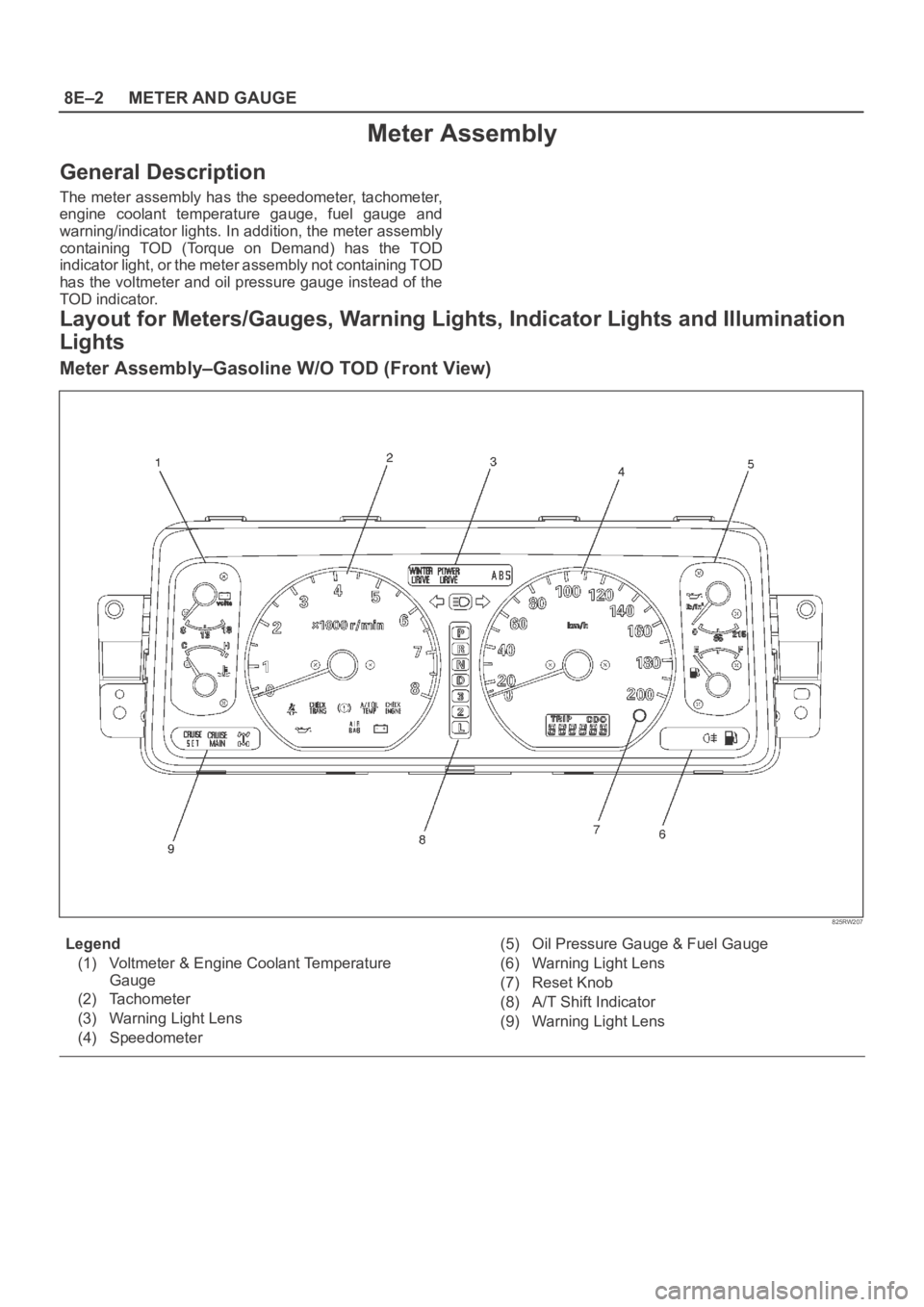
The meter assembly has the speedometer, tachometer,
engine coolant temperature gauge, fuel gauge and
warning/indicator lights. In addition, the meter assembly
containing TOD (Torque on Demand) has the TOD
indicator light, or the meter assembly not containing TOD
has the voltmeter and oil pressure gauge instead of the
TOD indicator.
Layout for Meters/Gauges, Warning Lights, Indicator Lights and Illumination
Lights
Meter Assembly–Gasoline W/O TOD (Front View)
825RW207
Legend
(1) Voltmeter & Engine Coolant Temperature
Gauge
(2) Tachometer
(3) Warning Light Lens
(4) Speedometer(5) Oil Pressure Gauge & Fuel Gauge
(6) Warning Light Lens
(7) Reset Knob
(8) A/T Shift Indicator
(9) Warning Light Lens
Page 3361 of 6000
8H–22SECURITY AND LOCKS
Anti-theft System
General Description
The circuit consists of the starter switch, anti-theft &
keyless entry control unit, anti-theft horn, front door and
tailgate key switch (detect and tamper switch), door lock
(& power window) switch, door lock actuator for each
door, engine hood switch, clutch start switch (M/T),
ANTI-THEFT indicator light and mode switch (A/T).
The system operates as follows: After locking the starter
switch and removing the starter key (this sets the alarm),
if the door is unlocked in any way other than with the
proper key, the headlights start flashing, the horn sounds,
and the starter circuit is disabled. (However, the engine
hood and all the doors must be locked and closed.)
Once the system has been placed in the warning or alarm
condition, it can be released only when the starter switch
is shifted from “OFF” to “ACC” by the starter key, or when
the lock of the front door or the tailgate is released (to
activate the detect switch) by the starter key.
Anti-theft & Keyless Entry Control
Unit Removal
1. Disconnect the battery ground cable.
2. Remove the front console assembly.
Refer to the Instrument Panel Assembly in Body
Structure section.
3. Remove the lower cluster assembly.
Refer to the Instrument Panel Assembly in Body
Structure section.
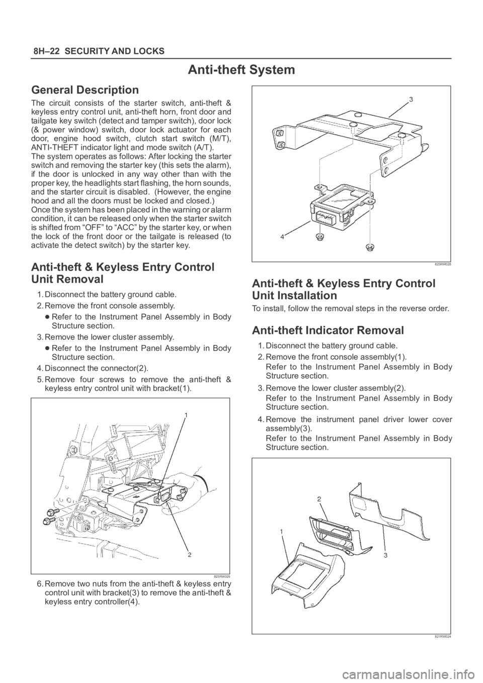
4. Disconnect the connector(2).
5. Remove four screws to remove the anti-theft &
keyless entry control unit with bracket(1).
825RW029
6. Remove two nuts from the anti-theft & keyless entry
control unit with bracket(3) to remove the anti-theft &
keyless entry controller(4).
825RW028
Anti-theft & Keyless Entry Control
Unit Installation
To install, follow the removal steps in the reverse order.
Anti-theft Indicator Removal
1. Disconnect the battery ground cable.
2. Remove the front console assembly(1).
Refer to the Instrument Panel Assembly in Body
Structure section.
3. Remove the lower cluster assembly(2).
Refer to the Instrument Panel Assembly in Body
Structure section.
4. Remove the instrument panel driver lower cover
assembly(3).
Refer to the Instrument Panel Assembly in Body
Structure section.
821RW024
Page 3552 of 6000
10A–1
CRUISE CONTROL SYSTEM
CONTROL SYSTEM
CRUISE CONTROL SYSTEM
CONTENTS
Service Precaution 10A–1. . . . . . . . . . . . . . . . . . . . . .
General Description 10A–1. . . . . . . . . . . . . . . . . . . . .
Diagnosis 10A–2. . . . . . . . . . . . . . . . . . . . . . . . . . . . . .
Brake Switch 10A–2. . . . . . . . . . . . . . . . . . . . . . . . . . .
Removal 10A–2. . . . . . . . . . . . . . . . . . . . . . . . . . . . .
Installation 10A–2. . . . . . . . . . . . . . . . . . . . . . . . . . . .
Adjustment 10A–3. . . . . . . . . . . . . . . . . . . . . . . . . . .
Clutch Switch 10A–3. . . . . . . . . . . . . . . . . . . . . . . . . . .
Removal and Installation 10A–3. . . . . . . . . . . . . . .
Adjustment 10A–3. . . . . . . . . . . . . . . . . . . . . . . . . . .
Starter Switch 10A–4. . . . . . . . . . . . . . . . . . . . . . . . . . .
Removal 10A–4. . . . . . . . . . . . . . . . . . . . . . . . . . . . .
Installation 10A–4. . . . . . . . . . . . . . . . . . . . . . . . . . . .
Cruise Control Main Switch 10A–5. . . . . . . . . . . . . . . Removal 10A–5. . . . . . . . . . . . . . . . . . . . . . . . . . . . .
Installation 10A–5. . . . . . . . . . . . . . . . . . . . . . . . . . . .
Cruise Control Switch (Combination Switch) 10A–5
Removal and Installation 10A–5. . . . . . . . . . . . . . .
Cruise Control Unit 10A–6. . . . . . . . . . . . . . . . . . . . . .
Removal 10A–6. . . . . . . . . . . . . . . . . . . . . . . . . . . . .
Installation 10A–6. . . . . . . . . . . . . . . . . . . . . . . . . . . .
Cruise Actuator 10A–7. . . . . . . . . . . . . . . . . . . . . . . . .
Actuator Cable Diagram (LHD) 10A–7. . . . . . . . . .
Actuator Cable Diagram (RHD) 10A–7. . . . . . . . . .
Removal 10A–8. . . . . . . . . . . . . . . . . . . . . . . . . . . . .
Installation 10A–8. . . . . . . . . . . . . . . . . . . . . . . . . . . .
Mode Switch 10A–8. . . . . . . . . . . . . . . . . . . . . . . . . . . .
Removal and Installation 10A–8. . . . . . . . . . . . . . .
Service Precaution
WARNING: IF SO EQUIPPED WITH A
SUPPLEMENTAL RESTRAINT SYSTEM (SRS),
REFER TO THE SRS COMPONENT AND WIRING
LOCATION VIEW IN ORDER TO DETERMINE
WHETHER YOU ARE PERFORMING SERVICE ON OR
NEAR THE SRS COMPONENTS OR THE SRS
WIRING. WHEN YOU ARE PERFORMING SERVICE
ON OR NEAR THE SRS COMPONENTS OR THE SRS
WIRING, REFER TO THE SRS SERVICE
INFORMATION. FAILURE TO FOLLOW WARNINGS
COULD RESULT IN POSSIBLE AIR BAG
DEPLOYMENT, PERSONAL INJURY, OR
OTHERWISE UNNEEDED SRS SYSTEM REPAIRS.
CAUTION: Always use the correct fastener in the
proper location. When you replace a fastener, use
ONLY the exact part number for that application.
ISUZU will call out those fasteners that require a
replacement after removal. ISUZU will also call out
the fasteners that require thread lockers or thread
sealant. UNLESS OTHERWISE SPECIFIED, do not
use supplemental coatings (Paints, greases, or other
corrosion inhibitors) on threaded fasteners or
fastener joint interfaces. Generally, such coatings
adversely affect the fastener torque and the joint
clamping force, and may damage the fastener. When
you install fasteners, use the correct tightening
sequence and specifications. Following these
instructions can help you avoid damage to parts and
systems.
General Description
The cruise control keeps the vehicle running at a fixed
speed until a signal canceling this fixed speed is received .
When the main switch “AUTO CRUISE” is turned on with
the vehicle in the running mode, the battery voltage is
applied to the control unit. When a signal from the control
switch is input to the control unit while the vehicle is in this
state, the cruise control actuator is activated to operate
the system. Also, while the system is operating, the
“AUTO CRUISE” indicator light in the meter assembly
lights up.
1. SET/COAST Switch Function
1.Set Function: When the SET/COAST switch is
pressed and released with the main switch on, the
speed at which the vehicle is running at that moment
is stored in the memory, and the vehicle automatically
runs at the stored speed.
2.Coast-down Function: When the SET/COAST
switch is kept on while the vehicle in running, the
vehicle decelerates during that time. The speed at
which vehicle is running when the control switch is
turned off is stored in the memory, and the vehicle
automatically returns to the stored speed.
3.Tap-down Function: When the SET/COAST switch
is turned on and off instantaneously while the vehicle
is running, the vehicle decelerates a mile for each
on/off operation. The vehicle speed at which the
vehicle was running when the SET/COAST was
turned off last is stored in the memory, and the vehicle
automatically returns to this stored speed.
Page 4500 of 6000
6A–4
ENGINE MECHANICAL
Engine Diagnosis
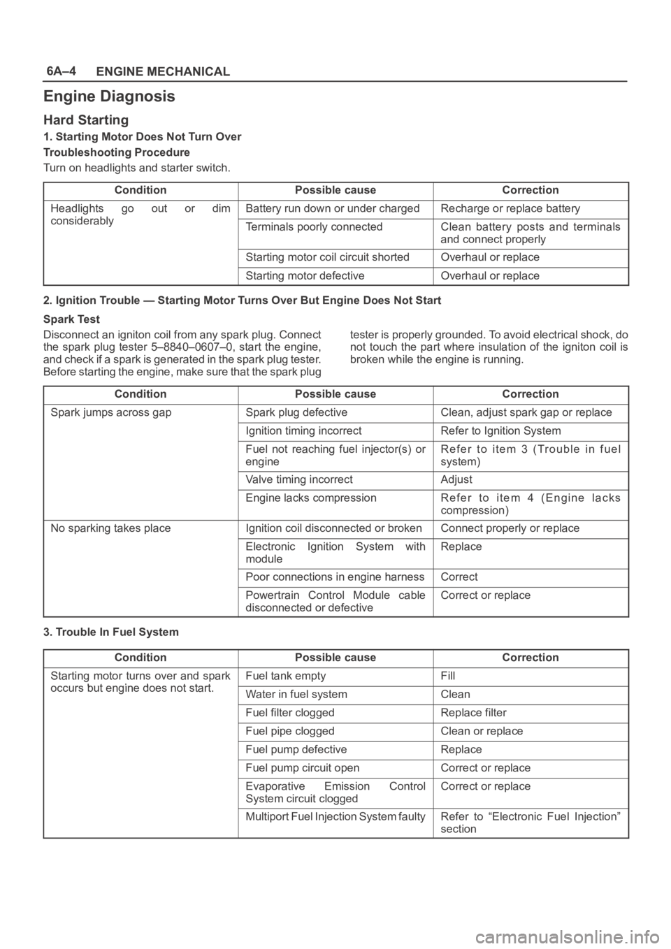
Hard Starting
1. Starting Motor Does Not Turn Over
Troubleshooting Procedure
Turn on headlights and starter switch.
Condition
Possible causeCorrection
Headlights go out or dim
considerably
Battery run down or under chargedRecharge or replace battery
considerablyTerminals poorly connectedClean battery posts and terminals
and connect properly
Starting motor coil circuit shortedOverhaul or replace
Starting motor defectiveOverhaul or replace
2. Ignition Trouble — Starting Motor Turns Over But Engine Does Not Start
Spark Test
Disconnect an igniton coil from any spark plug. Connect
the spark plug tester 5–8840–0607–0, start the engine,
a n d c h e c k i f a s p a r k i s g e n e r a t e d in t h e s p a r k p l u g t e s t e r.
Before starting the engine, make sure that the spark plugtester is properly grounded. To avoid electrical shock, do
not touch the part where insulation of the igniton coil is
broken while the engine is running.
Condition
Possible causeCorrection
Spark jumps across gapSpark plug defectiveClean, adjust spark gap or replace
Ignition timing incorrectRefer to Ignition System
Fuel not reaching fuel injector(s) or
engineRefer to item 3 (Trouble in fuel
system)
Valve timing incorrectAdjust
Engine lacks compressionRefer to item 4 (Engine lacks
compression)
No sparking takes placeIgnition coil disconnected or brokenConnect properly or replace
Electronic Ignition System with
moduleReplace
Poor connections in engine harnessCorrect
Powertrain Control Module cable
disconnected or defectiveCorrect or replace
3. Trouble In Fuel System
Condition
Possible causeCorrection
Starting motor turns over and spark
occurs but engine does not start
Fuel tank emptyFill
occurs but engine does not start.Water in fuel systemClean
Fuel filter cloggedReplace filter
Fuel pipe cloggedClean or replace
Fuel pump defectiveReplace
Fuel pump circuit openCorrect or replace
Evaporative Emission Control
System circuit cloggedCorrect or replace
Multiport Fuel Injection System faultyRefer to “Electronic Fuel Injection”
section
Page 4622 of 6000
ENGINE ELECTRICAL6D1–3
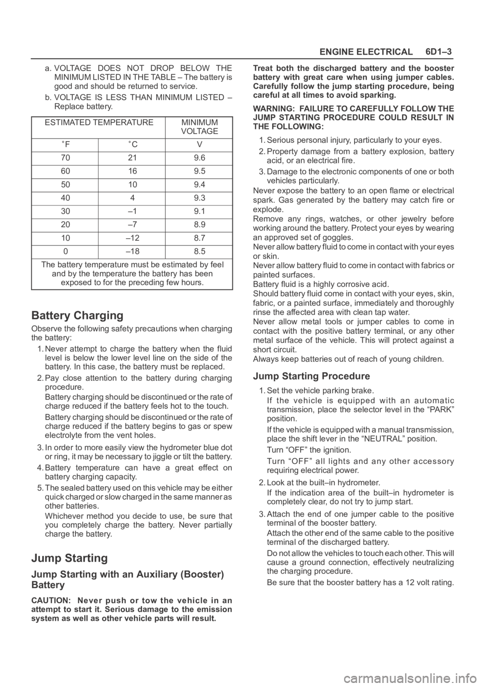
a. VOLTAGE DOES NOT DROP BELOW THE
MINIMUM LISTED IN THE TABLE – The battery is
good and should be returned to service.
b. VOLTAGE IS LESS THAN MINIMUM LISTED –
Replace battery.
ESTIMATED TEMPERATURE
MINIMUM
VOLTAGE
FCV
70219.6
60169.5
50109.4
4049.3
30–19.1
20–78.9
10–128.7
0–188.5
The battery temperature must be estimated by feel
and by the temperature the battery has been
exposed to for the preceding few hours.
Battery Charging
Observe the following safety precautions when charging
the battery:
1. Never attempt to charge the battery when the fluid
level is below the lower level line on the side of the
battery. In this case, the battery must be replaced.
2. Pay close attention to the battery during charging
procedure.
Battery charging should be discontinued or the rate of
charge reduced if the battery feels hot to the touch.
Battery charging should be discontinued or the rate of
charge reduced if the battery begins to gas or spew
electrolyte from the vent holes.
3. In order to more easily view the hydrometer blue dot
or ring, it may be necessary to jiggle or tilt the battery.
4. Battery temperature can have a great effect on
battery charging capacity.
5. The sealed battery used on this vehicle may be either
quick charged or slow charged in the same manner as
other batteries.
Whichever method you decide to use, be sure that
you completely charge the battery. Never partially
charge the battery.
Jump Starting
Jump Starting with an Auxiliary (Booster)
Battery
CAUTION: Never push or tow the vehicle in an
attempt to start it. Serious damage to the emission
system as well as other vehicle parts will result.Treat both the discharged battery and the booster
battery with great care when using jumper cables.
Carefully follow the jump starting procedure, being
careful at all times to avoid sparking.
WARNING: FAILURE TO CAREFULLY FOLLOW THE
JUMP STARTING PROCEDURE COULD RESULT IN
THE FOLLOWING:
1. Serious personal injury, particularly to your eyes.
2. Property damage from a battery explosion, battery
acid, or an electrical fire.
3. Damage to the electronic components of one or both
vehicles particularly.
Never expose the battery to an open flame or electrical
spark. Gas generated by the battery may catch fire or
explode.
Remove any rings, watches, or other jewelry before
working around the battery. Protect your eyes by wearing
an approved set of goggles.
Never allow battery fluid to come in contact with your eyes
or skin.
Never allow battery fluid to come in contact with fabrics or
painted surfaces.
Battery fluid is a highly corrosive acid.
Should battery fluid come in contact with your eyes, skin,
fabric, or a painted surface, immediately and thoroughly
rinse the affected area with clean tap water.
Never allow metal tools or jumper cables to come in
contact with the positive battery terminal, or any other
metal surface of the vehicle. This will protect against a
short circuit.
Always keep batteries out of reach of young children.
Jump Starting Procedure
1. Set the vehicle parking brake.
If the vehicle is equipped with an automatic
transmission, place the selector level in the “PARK”
position.
If the vehicle is equipped with a manual transmission,
place the shift lever in the “NEUTRAL” position.
Turn “OFF” the ignition.
Turn “OFF” all lights and any other accessory
requiring electrical power.
2. Look at the built–in hydrometer.
If the indication area of the built–in hydrometer is
completely clear, do not try to jump start.
3. Attach the end of one jumper cable to the positive
terminal of the booster battery.
Attach the other end of the same cable to the positive
terminal of the discharged battery.
Do not allow the vehicles to touch each other. This will
cause a ground connection, effectively neutralizing
the charging procedure.
Be sure that the booster battery has a 12 volt rating.
Page 4650 of 6000
6D3–19 STARTING AND CHARGING SYSTEM
Generator
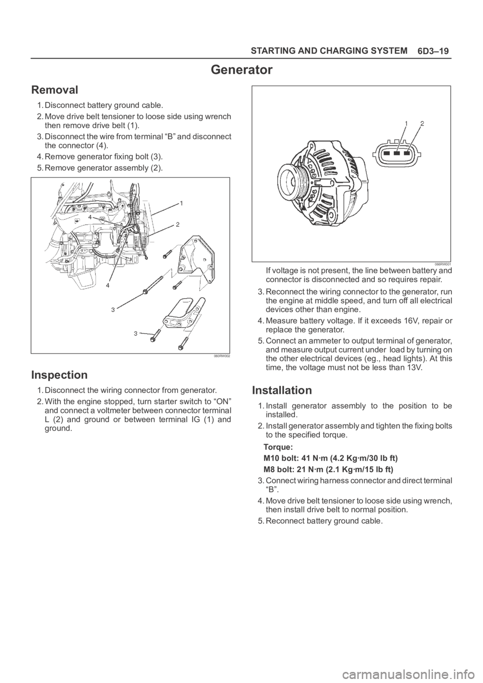
Removal
1. Disconnect battery ground cable.
2. Move drive belt tensioner to loose side using wrench
then remove drive belt (1).
3. Disconnect the wire from terminal “B” and disconnect
the connector (4).
4. Remove generator fixing bolt (3).
5. Remove generator assembly (2).
060RW002
Inspection
1. Disconnect the wiring connector from generator.
2. With the engine stopped, turn starter switch to “ON”
and connect a voltmeter between connector terminal
L (2) and ground or between terminal IG (1) and
ground.
066RW001If voltage is not present, the line between battery and
connector is disconnected and so requires repair.
3. Reconnect the wiring connector to the generator, run
the engine at middle speed, and turn off all electrical
devices other than engine.
4. Measure battery voltage. If it exceeds 16V, repair or
replace the generator.
5. Connect an ammeter to output terminal of generator,
and measure output current under load by turning on
the other electrical devices (eg., head lights). At this
time, the voltage must not be less than 13V.
Installation
1. Install generator assembly to the position to be
installed.
2. Install generator assembly and tighten the fixing bolts
to the specified torque.
To r q u e :
M10 bolt: 41 Nꞏm (4.2 Kgꞏm/30 lb ft)
M8 bolt: 21 Nꞏm (2.1 Kgꞏm/15 lb ft)
3. Connect wiring harness connector and direct terminal
“B”.
4. Move drive belt tensioner to loose side using wrench,
then install drive belt to normal position.
5. Reconnect battery ground cable.
Page 4803 of 6000
6E–146
ENGINE DRIVEABILITY AND EMISSIONS
indicates a signal line shorted to ground or signal lines
shorted together. Disconnect the HO2S and connect
a test light between the HO2S ignition feed and heater
ground circuits. If the test light does not light for 2
seconds when the ignition is turned on, repair the open
ignition feed or sensor ground circuit as necessary. If
the test light lights and the HO2S signal and low circuits
are OK, replace the HO2S.
Intermittent test – With the Ignition “ON,” monitor the
HO2S signal voltage while moving the wiring harness
and related connectors. If the fault is induced, the
HO2S signal voltage will change. This may help isolate
the location of the malfunction.
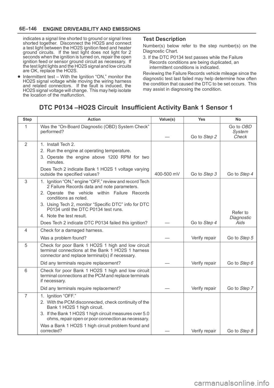
Test Description
Number(s) below refer to the step number(s) on the
Diagnostic Chart.
3. If the DTC P0134 test passes while the Failure
Records conditions are being duplicated, an
intermittent conditions is indicated.
Reviewing the Failure Records vehicle mileage since the
diagnostic test last failed may help determine how often
the condition that caused the DTC to be set occurs. This
may assist in diagnosing the condition.
DTC P0134 –HO2S Circuit Insufficient Activity Bank 1 Sensor 1
StepActionVa l u e ( s )Ye sNo
1Was the “On-Board Diagnostic (OBD) System Check”
performed?
—Go to Step 2
Go to OBD
System
Check
21. Install Tech 2.
2. Run the engine at operating temperature.
3. Operate the engine above 1200 RPM for two
minutes.
Does Tech 2 indicate Bank 1 HO2S 1 voltage varying
outside the specified values?
400-500 mVGo to Step 3Go to Step 4
31. Ignition “ON,” engine “OFF,” review and record Tech
2 Failure Records data and note parameters.
2. Operate the vehicle within Failure Records
conditions as noted.
3. Using Tech 2, monitor “Specific DTC” info for DTC
P0134 until the DTC P0134 test runs.
4. Note the test result.
Does Tech 2 indicate DTC P0134 failed this ignition?
—Go to Step 4
Refer to
Diagnostic
Aids
4Check for a damaged harness.
Was a problem found?
—Verify repairGo to Step 5
5Check for poor Bank 1 HO2S 1 high and low circuit
terminal connections at the Bank 1 HO2S 1 harness
connector and replace terminal(s) if necessary.
Did any terminals require replacement?
—Verify repairGo to Step 6
6Check for poor Bank 1 HO2S 1 high and low circuit
terminal connections at the PCM and replace terminals
if necessary.
Did any terminals require replacement?
—Verify repairGo to Step 7
71. Ignition “OFF.”
2. With the PCM disconnected, check continuity of the
Bank 1 HO2S 1 high circuit.
3. If the Bank 1 HO2S 1 high circuit measures over 5.0
ohms, repair open or poor connection as necessary.
Was a Bank 1 HO2S 1 high circuit problem found and
corrected?
—Verify repairGo to Step 8