1998 OPEL FRONTERA height
[x] Cancel search: heightPage 2528 of 6000
CLUTCH7C–19
Installation
1. Install damper cylinder assembly (except V6 LHD).
2. Install master cylinder assembly.
3. Install slave cylinder assembly and heat protector.
4. Install oil line pipe.
5. Install pedal assembly.
6. Install pin and jaw joint pin.
Adjustment
Clutch Pedal Adjustment
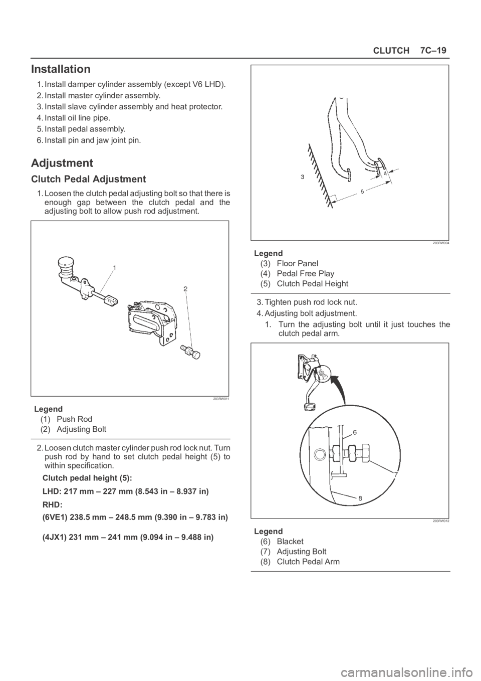
1. Loosen the clutch pedal adjusting bolt so that there is
enough gap between the clutch pedal and the
adjusting bolt to allow push rod adjustment.
203RW011
Legend
(1) Push Rod
(2) Adjusting Bolt
2. Loosen clutch master cylinder push rod lock nut. Turn
push rod by hand to set clutch pedal height (5) to
within specification.
Clutch pedal height (5):
LHD: 217 mm – 227 mm (8.543 in – 8.937 in)
RHD:
(6VE1) 238.5 mm – 248.5 mm (9.390 in – 9.783 in)
(4JX1) 231 mm – 241 mm (9.094 in – 9.488 in)
203RW004
Legend
(3) Floor Panel
(4) Pedal Free Play
(5) Clutch Pedal Height
3. Tighten push rod lock nut.
4. Adjusting bolt adjustment.
1. Turn the adjusting bolt until it just touches the
clutch pedal arm.
203RW012
Legend
(6) Blacket
(7) Adjusting Bolt
(8) Clutch Pedal Arm
Page 2529 of 6000
7C–20CLUTCH
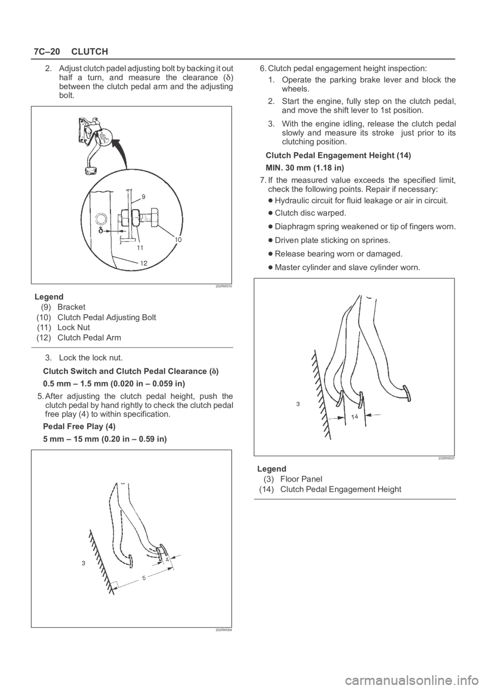
2. Adjust clutch padel adjusting bolt by backing it out
half a turn, and measure the clearance (
)
between the clutch pedal arm and the adjusting
bolt.
203RW010
Legend
(9) Bracket
(10) Clutch Pedal Adjusting Bolt
(11) Lock Nut
(12) Clutch Pedal Arm
3. Lock the lock nut.
Clutch Switch and Clutch Pedal Clearance (
)
0.5 mm – 1.5 mm (0.020 in – 0.059 in)
5. After adjusting the clutch pedal height, push the
clutch pedal by hand rightly to check the clutch pedal
free play (4) to within specification.
Pedal Free Play (4)
5 mm – 15 mm (0.20 in – 0.59 in)
203RW004
6. Clutch pedal engagement height inspection:
1. Operate the parking brake lever and block the
wheels.
2. Start the engine, fully step on the clutch pedal,
and move the shift lever to 1st position.
3. With the engine idling, release the clutch pedal
slowly and measure its stroke just prior to its
clutching position.
Clutch Pedal Engagement Height (14)
MIN. 30 mm (1.18 in)
7. If the measured value exceeds the specified limit,
check the following points. Repair if necessary:
Hydraulic circuit for fluid leakage or air in circuit.
Clutch disc warped.
Diaphragm spring weakened or tip of fingers worn.
Driven plate sticking on sprines.
Release bearing worn or damaged.
Master cylinder and slave cylinder worn.
203RW007
Legend
(3) Floor Panel
(14) Clutch Pedal Engagement Height
Page 2536 of 6000
CLUTCH7C–27
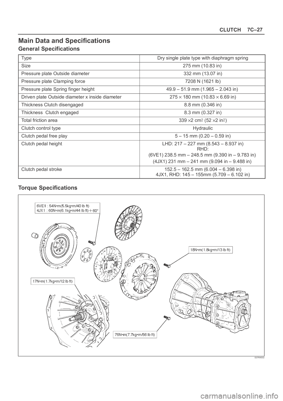
Main Data and Specifications
General Specifications
Ty p eDry single plate type with diaphragm spring
Size275 mm (10.83 in)
Pressure plate Outside diameter332 mm (13.07 in)
Pressure plate Clamping force7208 N (1621 lb)
Pressure plate Spring finger height49.9–51.9mm(1.965–2.043in)
Driven plate Outside diameter x inside diameter275180 mm (10.836.69 in)
Thickness Clutch disengaged8.8 mm (0.346 in)
Thickness Clutch engaged8.3 mm (0.327 in)
Total friction area 3392cm(522in)
Clutch control type Hydraulic
Clutch pedal free play 5 – 15 mm (0.20 – 0.59 in)
Clutch pedal heightLHD: 217 – 227 mm (8.543 – 8.937 in)
RHD:
(6VE1) 238.5 mm – 248.5 mm (9.390 in – 9.783 in)
(4JX1) 231 mm – 241 mm (9.094 in – 9.488 in)
Clutch pedal stroke 152.5 – 162.5 mm (6.004 – 6.398 in)
4JX1, RHD: 145 – 155mm (5.709 – 6.102 in)
Torque Specifications
E07RW053
Page 3315 of 6000
SEATS8G–3
Installation
To install, follow the removal steps in the reverse order,
noting the following points:1. Tighten the front seat assembly fixing bolts to the
specified torque.
Torque: 40 Nꞏm (4.1 kgꞏm/30 lb ft)
2. Install the longest bolt to the rear inner side fixing
location, if this model is equipped with power seats.
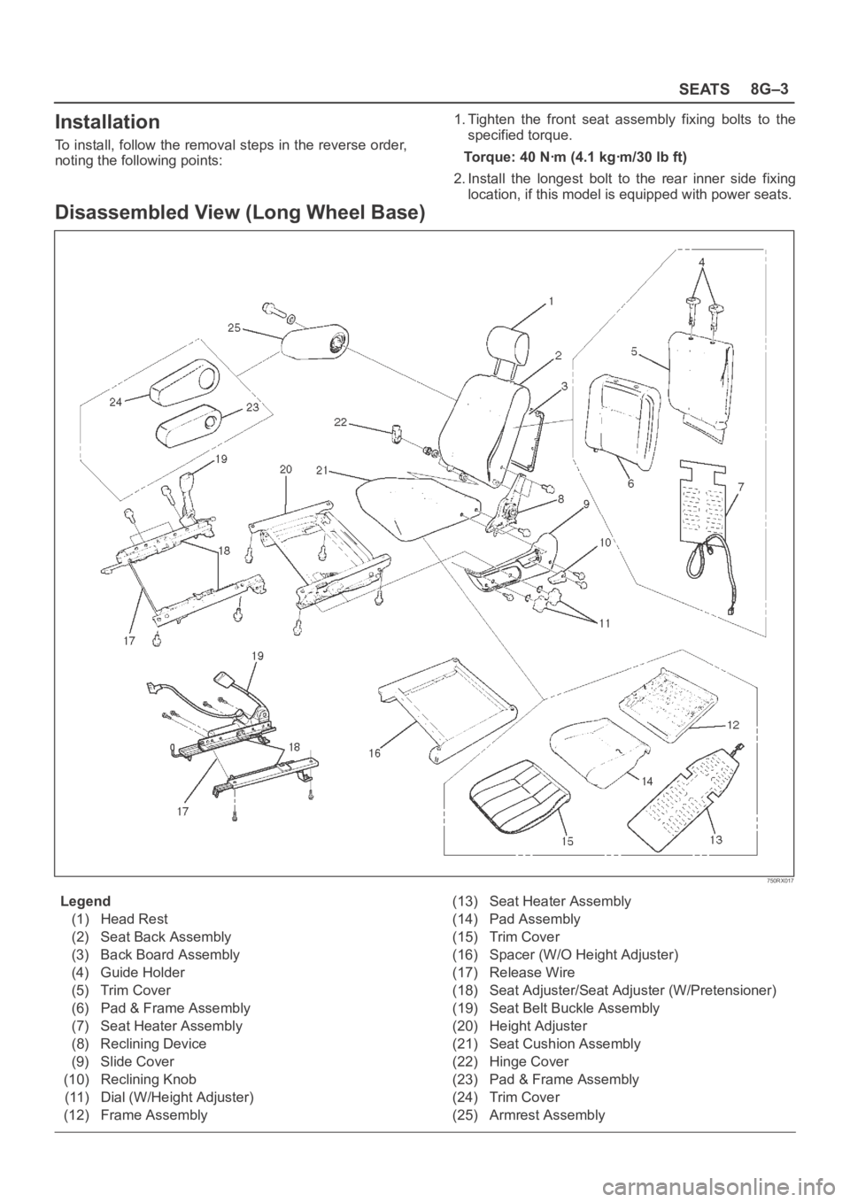
Disassembled View (Long Wheel Base)
750RX017
Legend
(1) Head Rest
(2) Seat Back Assembly
(3) Back Board Assembly
(4) Guide Holder
(5) Trim Cover
(6) Pad & Frame Assembly
(7) Seat Heater Assembly
(8) Reclining Device
(9) Slide Cover
(10) Reclining Knob
(11) Dial (W/Height Adjuster)
(12) Frame Assembly(13) Seat Heater Assembly
(14) Pad Assembly
(15) Trim Cover
(16) Spacer (W/O Height Adjuster)
(17) Release Wire
(18) Seat Adjuster/Seat Adjuster (W/Pretensioner)
(19) Seat Belt Buckle Assembly
(20) Height Adjuster
(21) Seat Cushion Assembly
(22) Hinge Cover
(23) Pad & Frame Assembly
(24) Trim Cover
(25) Armrest Assembly
Page 3316 of 6000
8G–4SEATS
Disassembly
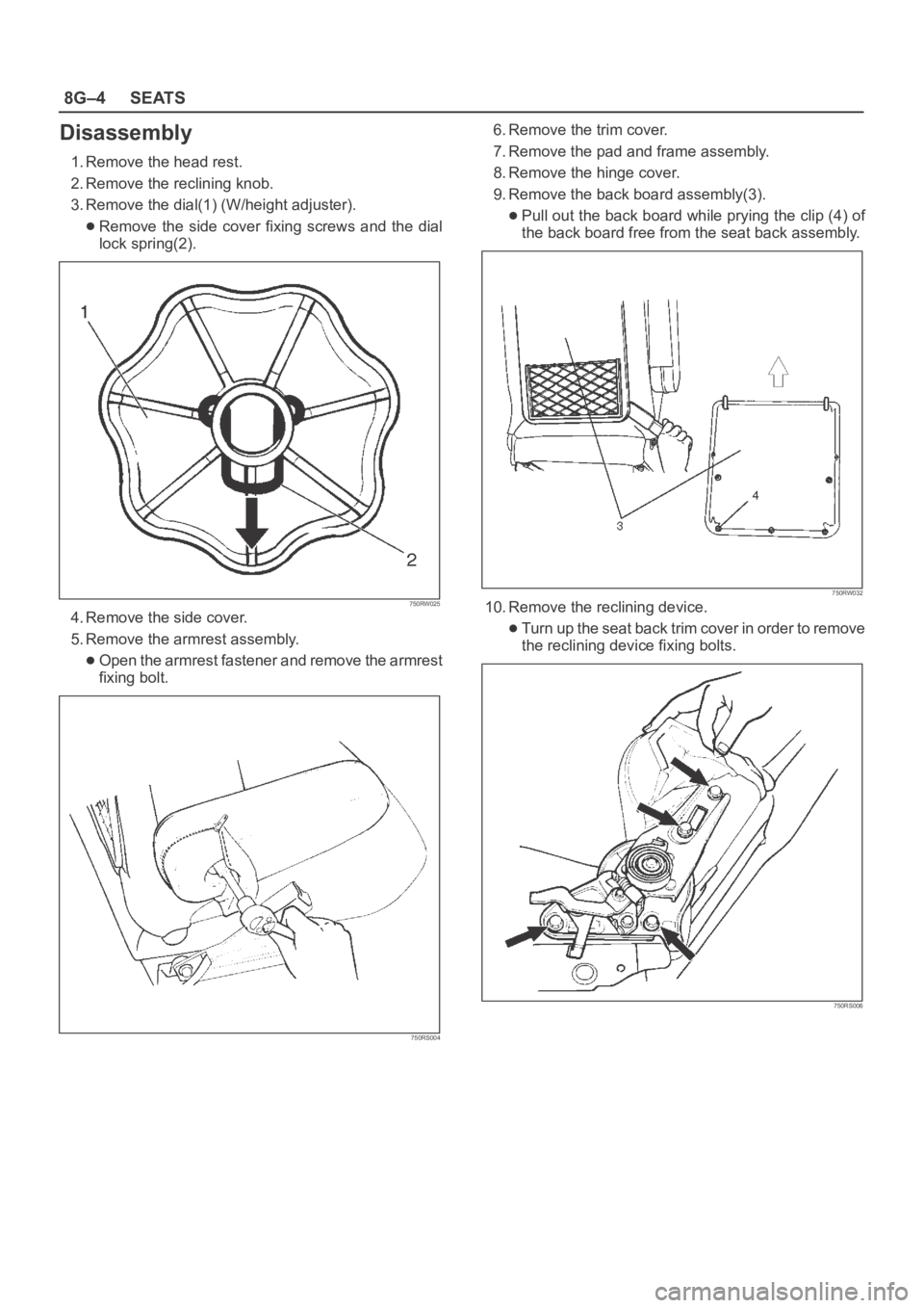
1. Remove the head rest.
2. Remove the reclining knob.
3. Remove the dial(1) (W/height adjuster).
Remove the side cover fixing screws and the dial
lock spring(2).
750RW025
4. Remove the side cover.
5. Remove the armrest assembly.
Open the armrest fastener and remove the armrest
fixing bolt.
750RS004
6. Remove the trim cover.
7. Remove the pad and frame assembly.
8. Remove the hinge cover.
9. Remove the back board assembly(3).
Pull out the back board while prying the clip (4) of
the back board free from the seat back assembly.
750RW032
10. Remove the reclining device.
Turn up the seat back trim cover in order to remove
the reclining device fixing bolts.
750RS006
Page 3317 of 6000
SEATS8G–5
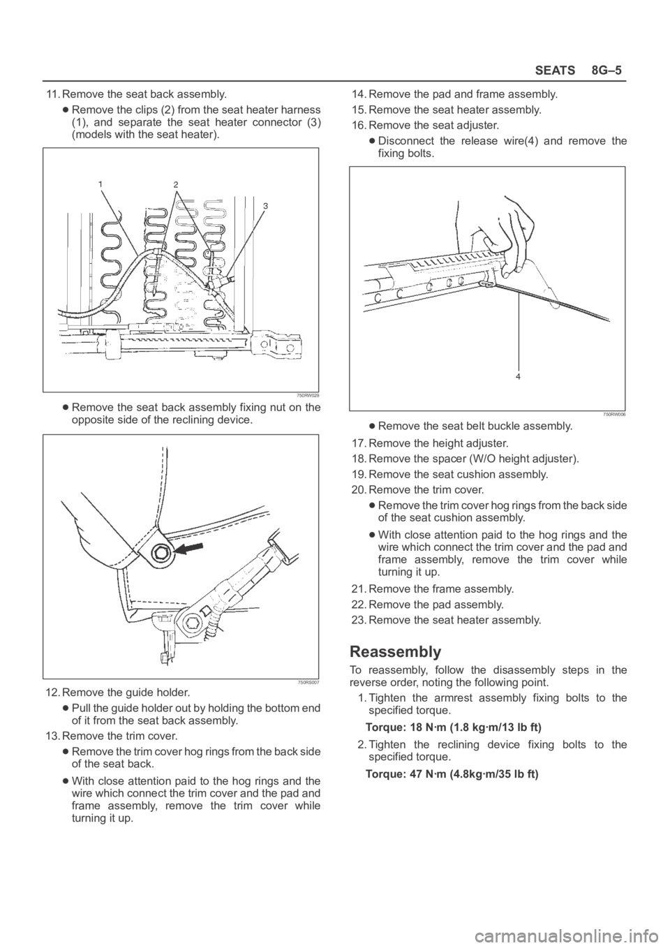
11. Remove the seat back assembly.
Remove the clips (2) from the seat heater harness
(1), and separate the seat heater connector (3)
(models with the seat heater).
750RW029
Remove the seat back assembly fixing nut on the
opposite side of the reclining device.
750RS007
12. Remove the guide holder.
Pull the guide holder out by holding the bottom end
of it from the seat back assembly.
13. Remove the trim cover.
Remove the trim cover hog rings from the back side
of the seat back.
With close attention paid to the hog rings and the
wire which connect the trim cover and the pad and
frame assembly, remove the trim cover while
turning it up.14. Remove the pad and frame assembly.
15. Remove the seat heater assembly.
16. Remove the seat adjuster.
Disconnect the release wire(4) and remove the
fixing bolts.
750RW006
Remove the seat belt buckle assembly.
17. Remove the height adjuster.
18. Remove the spacer (W/O height adjuster).
19. Remove the seat cushion assembly.
20. Remove the trim cover.
Remove the trim cover hog rings from the back side
of the seat cushion assembly.
With close attention paid to the hog rings and the
wire which connect the trim cover and the pad and
frame assembly, remove the trim cover while
turning it up.
21. Remove the frame assembly.
22. Remove the pad assembly.
23. Remove the seat heater assembly.
Reassembly
To reassembly, follow the disassembly steps in the
reverse order, noting the following point.
1. Tighten the armrest assembly fixing bolts to the
specified torque.
Torque: 18 Nꞏm (1.8 kgꞏm/13 lb ft)
2. Tighten the reclining device fixing bolts to the
specified torque.
Torque: 47 Nꞏm (4.8kgꞏm/35 lb ft)
Page 3448 of 6000
SUPPLEMENTAL RESTRAINT SYSTEM9J–11
Handling / Installation / Diagnosis
1. Air bag assembly should not be subjected to
temperatures above 93
C (200F).
2. Air bag assembly, and SDM should not be used if they
have been dropped from a height of 100 centimeters
(3.28 feet) or more.
3. When a SDM is replaced, it must be oriented with the
arrow on the sensor pointing toward the front of the
vehicle. It is very important for the SDM to be located
flat on the mounting surface, parallel to the vehicle
datum line. It is important that the SDM mounting
surface is free of any dirt or other foreign material.
4. Do not apply power to the SRS unless all components
are connected or a diagnostic chart requests it, as this
will set a diagnostic trouble code.
5. The “SRS Diagnostic System Check” must be the
starting point of any SRS diagnostics. The “SRS
Diagnostic System Check” will verify proper “AIR
BAG” warning lamp operation and will lead you to the
correct chart to diagnose any SRS malfunctions.
Bypassing these procedures may result in extended
diagnostic time, incorrect diagnosis, and incorrect
parts replacement.
Air Bag Assembly Handling /
Shipping / Scrapping
Live (Undeployed) Air Bag Assembly
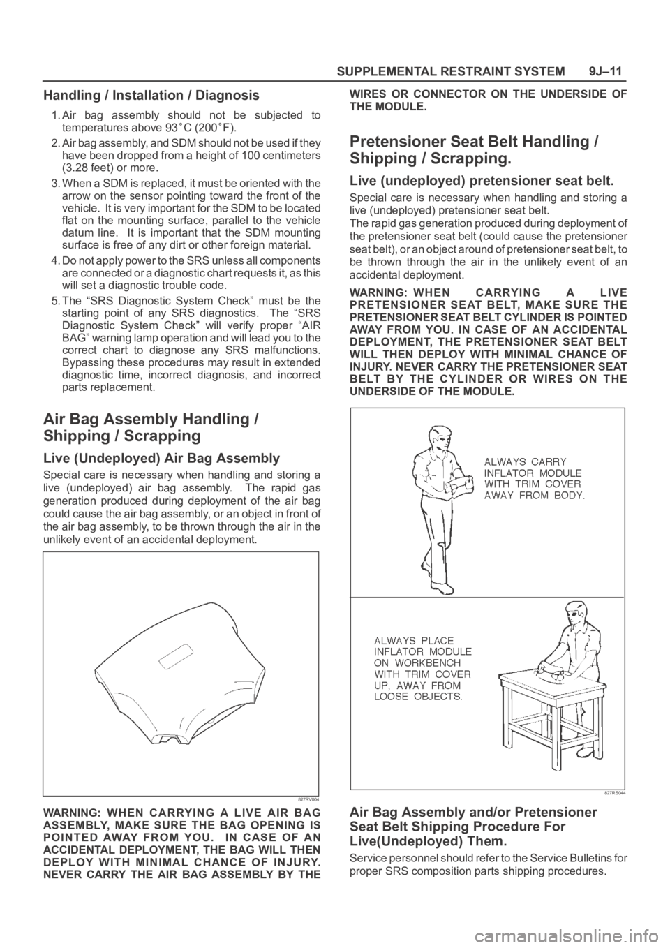
Special care is necessary when handling and storing a
live (undeployed) air bag assembly. The rapid gas
generation produced during deployment of the air bag
could cause the air bag assembly, or an object in front of
the air bag assembly, to be thrown through the air in the
unlikely event of an accidental deployment.
827RV004
WARNING: WHEN CARRYING A LIVE AIR BAG
ASSEMBLY, MAKE SURE THE BAG OPENING IS
POINTED AWAY FROM YOU. IN CASE OF AN
ACCIDENTAL DEPLOYMENT, THE BAG WILL THEN
DEPLOY WITH MINIMAL CHANCE OF INJURY.
NEVER CARRY THE AIR BAG ASSEMBLY BY THEWIRES OR CONNECTOR ON THE UNDERSIDE OF
THE MODULE.
Pretensioner Seat Belt Handling /
Shipping / Scrapping.
Live (undeployed) pretensioner seat belt.
Special care is necessary when handling and storing a
live (undeployed) pretensioner seat belt.
The rapid gas generation produced during deployment of
the pretensioner seat belt (could cause the pretensioner
seat belt), or an object around of pretensioner seat belt, to
be thrown through the air in the unlikely event of an
accidental deployment.
WARNING: WHEN CARRYING A LIVE
PRETENSIONER SEAT BELT, MAKE SURE THE
PRETENSIONER SEAT BELT CYLINDER IS POINTED
AWAY FROM YOU. IN CASE OF AN ACCIDENTAL
DEPLOYMENT, THE PRETENSIONER SEAT BELT
WILL THEN DEPLOY WITH MINIMAL CHANCE OF
INJURY. NEVER CARRY THE PRETENSIONER SEAT
BELT BY THE CYLINDER OR WIRES ON THE
UNDERSIDE OF THE MODULE.
827RS044
Air Bag Assembly and/or Pretensioner
Seat Belt Shipping Procedure For
Live(Undeployed) Them.
Service personnel should refer to the Service Bulletins for
proper SRS composition parts shipping procedures.
Page 3467 of 6000
SUPPLEMENTAL RESTRAINT SYSTEM 9J–30
Service Precautions for SRS
Component Service
CAUTION: When fasteners are removed, always
reinstall them at the same location from which they
were removed. If a fastener needs to be replaced, use
the correct part number fastener for that application.
If the correct part number fastener is not available, a
fastener of equal size and strength (or stronger) may
be used. fasteners that are not reused, and those
requiring thread locking compound will be called
out. The correct torque value must be used when
installing fasteners that require it. If the above
conditions are not followed, parts or system damage
could result.
WARNING: WHEN PERFORMING SERVICE ON OR
AROUND SRS COMPONENTS OR SRS WIRING,
FOLLOW THE PROCEDURES LISTED BELOW TO
TEMPORARILY DISABLE THE SRS. FAILURE TO
FOLLOW PROCEDURES COULD RESULT IN
POSSIBLE AIR BAG DEPLOYMENT, PERSONAL
INJURY OR OTHERWISE UNNEEDED SRS REPAIRS.
The SDM in Driver–Passenger SRS can maintain
sufficient voltage to cause a deployment for up to 15
seconds after the ignition switch is turned “OFF,” the
battery is disconnected, or the fuse powering the SDM is
removed.
Many of the service procedures require removal of the
“C–21” fuse, and disconnection of the air bag assembly
from the deployment loop to avoid an accidental
deployment. If the air bag assembly is disconnected from
the deployment loop as noted in the “Disabling the SRS”
procedure that follows, service can begin immediately
without waiting for the 15 second time period to expire.
Disabling The SRS
Removal
Turn the ignition switch to “OFF” and turn the steering
wheel so that the vehicle’s wheels are pointing straight
ahead.
1. Remove SRS fuse “C–21” from left dash side lower
fuse block or disconnect battery.
2. Disconnect yellow 2–pin connector at the base of
steering column.
3 . R e m o v e g l o v e b o x a s s e m b l y ; R e f e r t o “ P a s s e n g e r a i r
bag assembly replacement” in this section.
4. Disconnect passenger air bag assembly yellow 2–pin
connector behind the glove box assembly.
CAUTION: W i t h t h e “ C – 2 1 ” f u s e r e m o v e d a n d
ignition switch “ON,” the “AIR BAG” warning lamp
will be “ON.” This is normal operation and does not
indicate an SRS malfunction.
Enabling The SRS
Installation
Turn ignition switch to “LOCK” and remove key.
1. Connect yellow 2–pin connector passenger air bag
assembly.2. Install glove box assembly. Refer to “Passenger Air
Bag Assembly Replacement” in this section.
3. Connect yellow 2–pin connector at the base of the
steering column.
4. Install “AIR BAG” fuse “C–21” to left dash side lower
fuse block or connect battery.
Turn ignition switch to “ON” and verify that the “AIR BAG”
warning lamp turn on 3.5 seconds and then turns “OFF.” If
it does not operate as described, perform the “SRS
Diagnostic System Check” in this section.
Handling / Installation / Diagnosis
1. Air bag assembly should not be subjected to
temperatures above 93
C (200F).
2. Air bag assembly, and SDM should not be used if they
have been dropped from a height of 100 centimeters
(3.28 feet) or more.
3. When a SDM is replaced, it must be oriented with the
arrow on the SDM pointing toward the front of the
vehicle. It is very important for the SDM to be located
flat on the mounting surface, parallel to the vehicle
datum line. It is important that the SDM mounting
surface is free of any dirt or other foreign material.
4. Do not apply power to the SRS unless all components
are connected or a diagnostic chart requests it, as
this will set a diagnostic trouble code.
5. The “SRS Diagnostic System Check” must be the
starting point of any SRS diagnostics. The “SRS
Diagnostic System Check” will verify proper “AIR
BAG” warning lamp operation and will lead you to the
correct chart to diagnose any SRS malfunctions.
Bypassing these procedures may result in extended
diagnostic time, incorrect diagnosis, and incorrect
parts replacements.
Inspections Required After An Accident
CAUTION: C e r t a i n S R S c o m p o n e n t s m u s t b e
replaced after a frontal crash involving air bag
deployment.
In all types of accidents regardless of “Air Bag”
deployment, visually inspect all of the following
components and replace as required:
— Driver air bag assembly
— Passenger air bag assembly
— Driver pretensioner assembly
— Passenger pretensioner assembly
— Steering wheel
— SRS coil assembly
— Steering column
— Knee bolster and instrument panel mounting
attachments
— Driver seat and belt
— Passenger seat and belt
—SDM
SDM always should be checked according to “SDM
Replacement Guidelines.”