1998 OPEL FRONTERA Pressure fuel regulator
[x] Cancel search: Pressure fuel regulatorPage 1390 of 6000
6E–273 ENGINE DRIVEABILITY AND EMISSIONS
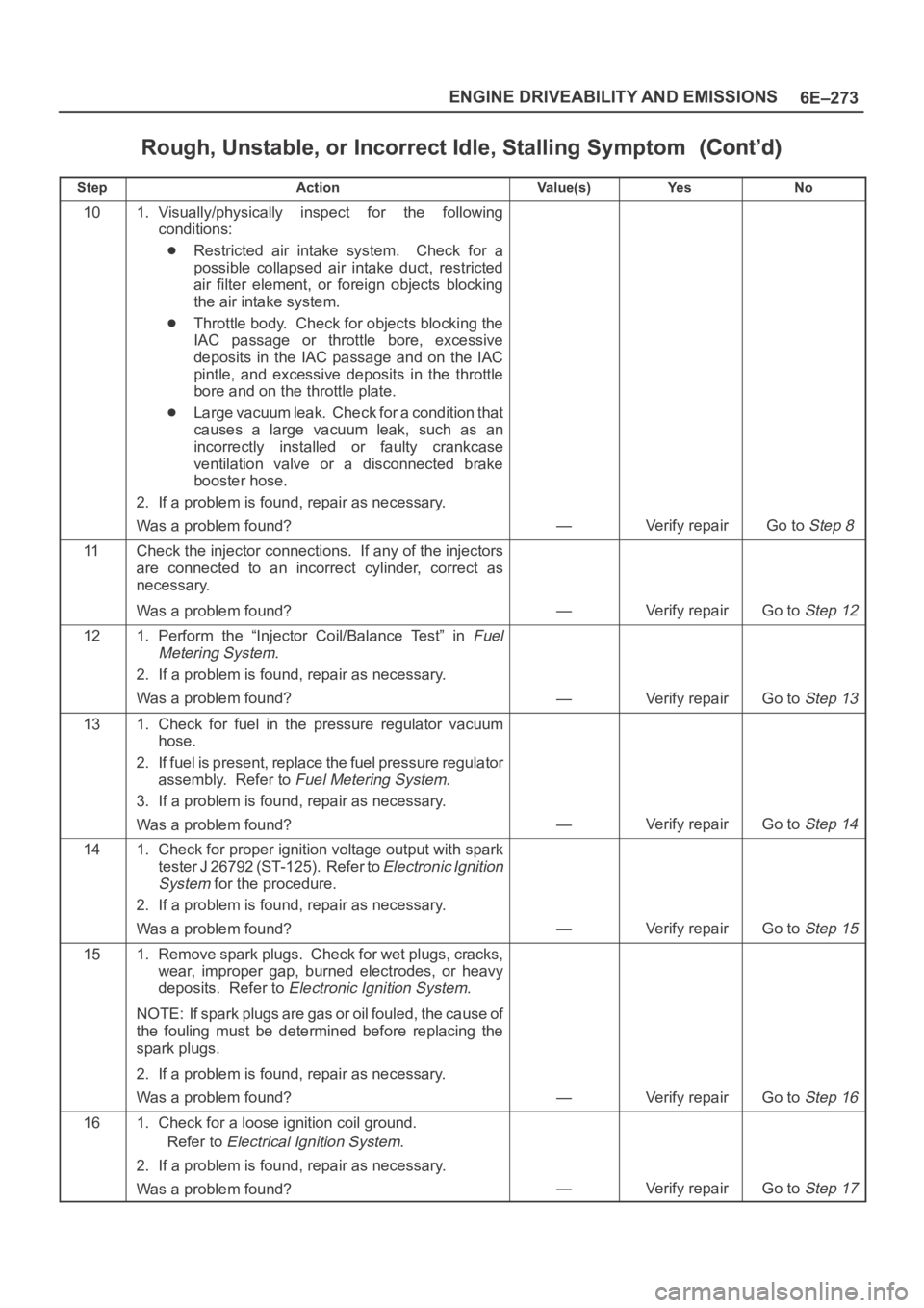
Rough, Unstable, or Incorrect Idle, Stalling Symptom
StepNo Ye s Va l u e ( s ) Action
101. Visually/physically inspect for the following
conditions:
Restricted air intake system. Check for a
possible collapsed air intake duct, restricted
air filter element, or foreign objects blocking
the air intake system.
Throttle body. Check for objects blocking the
IAC passage or throttle bore, excessive
deposits in the IAC passage and on the IAC
pintle, and excessive deposits in the throttle
bore and on the throttle plate.
Large vacuum leak. Check for a condition that
causes a large vacuum leak, such as an
incorrectly installed or faulty crankcase
ventilation valve or a disconnected brake
booster hose.
2. If a problem is found, repair as necessary.
Was a problem found?
—Verify repairGo to Step 8
11Check the injector connections. If any of the injectors
are connected to an incorrect cylinder, correct as
necessary.
Was a problem found?
—Verify repairGo to Step 12
121. Perform the “Injector Coil/Balance Test” in Fuel
Metering System
.
2. If a problem is found, repair as necessary.
Was a problem found?
—Verify repairGo to Step 13
131. Check for fuel in the pressure regulator vacuum
hose.
2. If fuel is present, replace the fuel pressure regulator
assembly. Refer to
Fuel Metering System.
3. If a problem is found, repair as necessary.
Was a problem found?
—Verify repairGo to Step 14
141. Check for proper ignition voltage output with spark
tester J 26792 (ST-125). Refer to
Electronic Ignition
System
for the procedure.
2. If a problem is found, repair as necessary.
Was a problem found?
—Verify repairGo to Step 15
151. Remove spark plugs. Check for wet plugs, cracks,
wear, improper gap, burned electrodes, or heavy
deposits. Refer to
Electronic Ignition System.
NOTE: If spark plugs are gas or oil fouled, the cause of
the fouling must be determined before replacing the
spark plugs.
2. If a problem is found, repair as necessary.
Was a problem found?
—Verify repairGo to Step 16
161. Check for a loose ignition coil ground.
Refer to
Electrical Ignition System.
2. If a problem is found, repair as necessary.
Was a problem found?
—Verify repairGo to Step 17
Page 1400 of 6000
6E–283 ENGINE DRIVEABILITY AND EMISSIONS
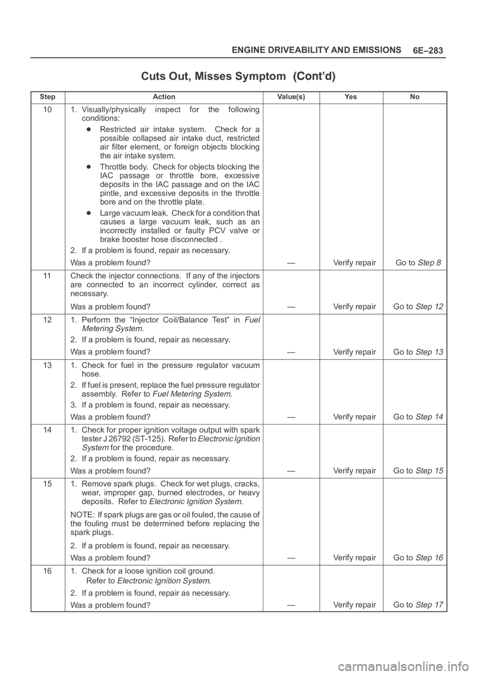
Cuts Out, Misses Symptom
StepNo Ye s Va l u e ( s ) Action
101. Visually/physically inspect for the following
conditions:
Restricted air intake system. Check for a
possible collapsed air intake duct, restricted
air filter element, or foreign objects blocking
the air intake system.
Throttle body. Check for objects blocking the
IAC passage or throttle bore, excessive
deposits in the IAC passage and on the IAC
pintle, and excessive deposits in the throttle
bore and on the throttle plate.
Large vacuum leak. Check for a condition that
causes a large vacuum leak, such as an
incorrectly installed or faulty PCV valve or
brake booster hose disconnected .
2. If a problem is found, repair as necessary.
Was a problem found?
—Verify repairGo to Step 8
11Check the injector connections. If any of the injectors
are connected to an incorrect cylinder, correct as
necessary.
Was a problem found?
—Verify repairGo to Step 12
121. Perform the “Injector Coil/Balance Test” in Fuel
Metering System
.
2. If a problem is found, repair as necessary.
Was a problem found?
—Verify repairGo to Step 13
131. Check for fuel in the pressure regulator vacuum
hose.
2. If fuel is present, replace the fuel pressure regulator
assembly. Refer to
Fuel Metering System.
3. If a problem is found, repair as necessary.
Was a problem found?
—Verify repairGo to Step 14
141. Check for proper ignition voltage output with spark
tester J 26792 (ST-125). Refer to
Electronic Ignition
System
for the procedure.
2. If a problem is found, repair as necessary.
Was a problem found?
—Verify repairGo to Step 15
151. Remove spark plugs. Check for wet plugs, cracks,
wear, improper gap, burned electrodes, or heavy
deposits. Refer to
Electronic Ignition System.
NOTE: If spark plugs are gas or oil fouled, the cause of
the fouling must be determined before replacing the
spark plugs.
2. If a problem is found, repair as necessary.
Was a problem found?
—Verify repairGo to Step 16
161. Check for a loose ignition coil ground.
Refer to
Electronic Ignition System.
2. If a problem is found, repair as necessary.
Was a problem found?
—Verify repairGo to Step 17
Page 1432 of 6000
6E–315 ENGINE DRIVEABILITY AND EMISSIONS
Installation Procedure
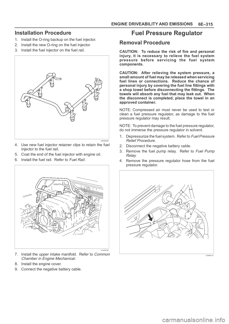
1. Install the O-ring backup on the fuel injector.
2. Install the new O-ring on the fuel injector.
3. Install the fuel injector on the fuel rail.
055RW009
4. Use new fuel injector retainer clips to retain the fuel
injector to the fuel rail.
5. Coat the end of the fuel injector with engine oil.
6. Install the fuel rail. Refer to
Fuel Rail.
014RW164
7. Install the upper intake manifold. Refer to Common
Chamber in Engine Mechanical.
8. Install the engine cover.
9. Connect the negative battery cable.
Fuel Pressure Regulator
Removal Procedure
CAUTION: To reduce the risk of fire and personal
injury, it is necessary to relieve the fuel system
pressure before servicing the fuel system
components.
CAUTION: After relieving the system pressure, a
small amount of fuel may be released when servicing
fuel lines or connections. Reduce the chance of
personal injury by covering the fuel line fittings with
a shop towel before disconnecting the fittings. The
towels will absorb any fuel that may leak out. When
the disconnect is completed, place the towel in an
approved container.
NOTE: Compressed air must never be used to test or
clean a fuel pressure regulator, as damage to the fuel
pressure regulator may result.
NOTE: To prevent damage to the fuel pressure regulator,
do not immerse the pressure regulator in solvent.
1. Depressurize the fuel system. Refer to
Fuel Pressure
Relief Procedure
.
2. Disconnect the negative battery cable.
3. Remove the fuel pump relay. Refer to
Fuel Pump
Relay
.
4. Remove the pressure regulator hose from the fuel
pressure regulator.
014RW110
Page 1433 of 6000

6E–316
ENGINE DRIVEABILITY AND EMISSIONS
5. Remove the two bolts from the protector that secures
the common chamber.
014RW109
6. Remove the fuel pressure regulator attaching screw.
F06RW043
7. Remove the fuel pressure regulator from the fuel rail.
Disassembly Procedure
1. Remove the O-ring from the fuel pressure regulator.
2. Loosen the swivel nut.
3. Remove the fuel return line from the fuel pressure
regulator.
4. Remove the O-ring from the fuel return line.
The O-ring may be left inside the fuel pressure
regulator instead of on the fuel return line.
F06RW043
Assembly Procedure
1. Install a new O-ring on the fuel return line.
2. Install the fuel return line on the fuel pressure
regulator.
NOTE: Do not over-tighten the swivel nut on the fuel
pressure regulator. The fuel pressure regulator can be
damaged and fuel may leak if the swivel nut is
over-tightened.
3. Tighten the swivel nut.
4. Install a new O-ring on the fuel pressure regulator.
Page 1434 of 6000
6E–317 ENGINE DRIVEABILITY AND EMISSIONS
Installation Procedure
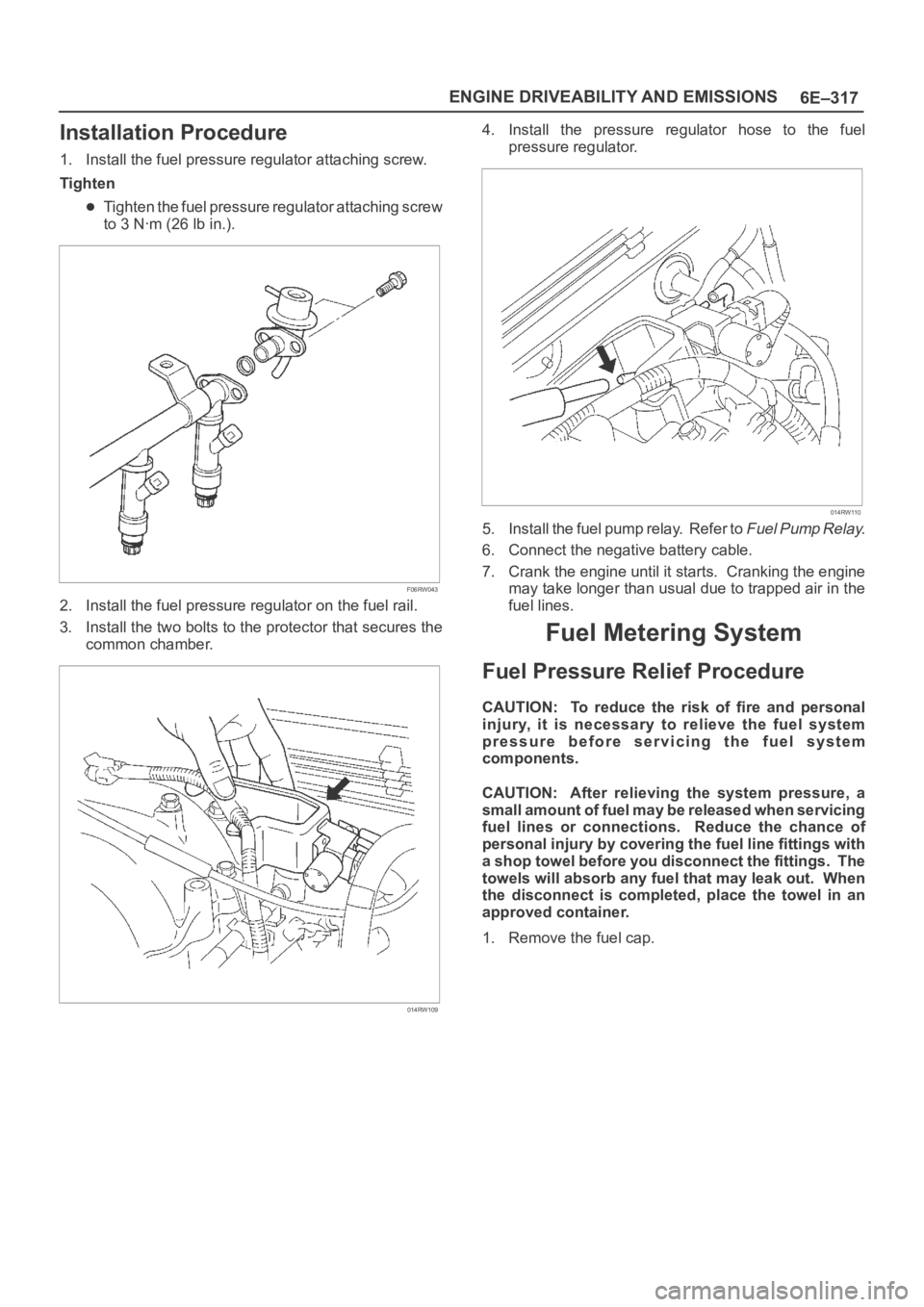
1. Install the fuel pressure regulator attaching screw.
Tighten
Tighten the fuel pressure regulator attaching screw
to 3 Nꞏm (26 lb in.).
F06RW043
2. Install the fuel pressure regulator on the fuel rail.
3. Install the two bolts to the protector that secures the
common chamber.
014RW109
4. Install the pressure regulator hose to the fuel
pressure regulator.
014RW110
5. Install the fuel pump relay. Refer to Fuel Pump Relay.
6. Connect the negative battery cable.
7. Crank the engine until it starts. Cranking the engine
may take longer than usual due to trapped air in the
fuel lines.
Fuel Metering System
Fuel Pressure Relief Procedure
CAUTION: To reduce the risk of fire and personal
injury, it is necessary to relieve the fuel system
pressure before servicing the fuel system
components.
CAUTION: After relieving the system pressure, a
small amount of fuel may be released when servicing
fuel lines or connections. Reduce the chance of
personal injury by covering the fuel line fittings with
a shop towel before you disconnect the fittings. The
towels will absorb any fuel that may leak out. When
the disconnect is completed, place the towel in an
approved container.
1. Remove the fuel cap.
Page 1437 of 6000
6E–320
ENGINE DRIVEABILITY AND EMISSIONS
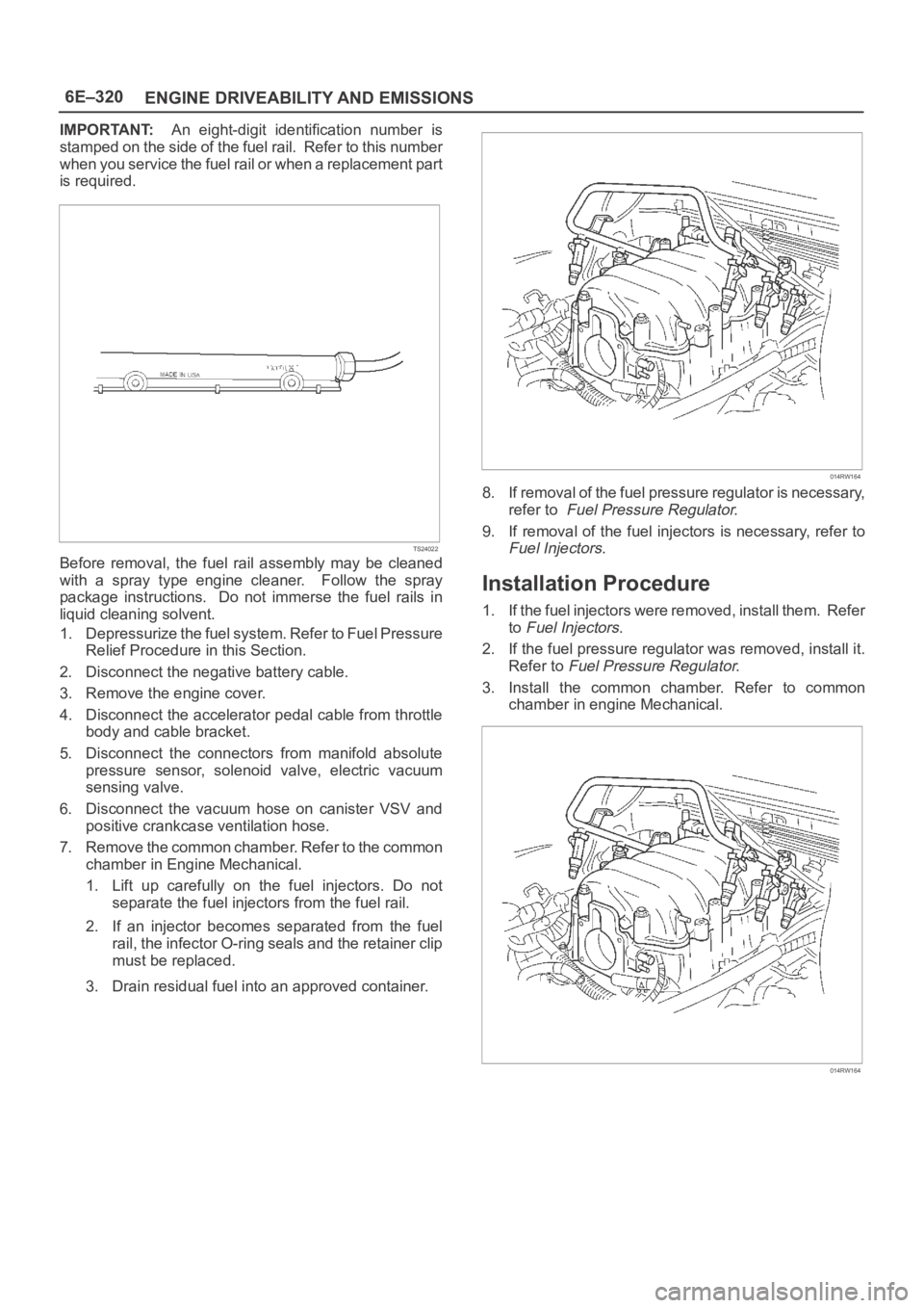
IMPORTANT:An eight-digit identification number is
stamped on the side of the fuel rail. Refer to this number
when you service the fuel rail or when a replacement part
is required.
TS24022
Before removal, the fuel rail assembly may be cleaned
with a spray type engine cleaner. Follow the spray
package instructions. Do not immerse the fuel rails in
liquid cleaning solvent.
1. Depressurize the fuel system. Refer to Fuel Pressure
Relief Procedure in this Section.
2. Disconnect the negative battery cable.
3. Remove the engine cover.
4. Disconnect the accelerator pedal cable from throttle
body and cable bracket.
5. Disconnect the connectors from manifold absolute
pressure sensor, solenoid valve, electric vacuum
sensing valve.
6. Disconnect the vacuum hose on canister VSV and
positive crankcase ventilation hose.
7. Remove the common chamber. Refer to the common
chamber in Engine Mechanical.
1. Lift up carefully on the fuel injectors. Do not
separate the fuel injectors from the fuel rail.
2. If an injector becomes separated from the fuel
rail, the infector O-ring seals and the retainer clip
must be replaced.
3. Drain residual fuel into an approved container.
014RW164
8. If removal of the fuel pressure regulator is necessary,
refer to
Fuel Pressure Regulator.
9. If removal of the fuel injectors is necessary, refer to
Fuel Injectors.
Installation Procedure
1. If the fuel injectors were removed, install them. Refer
to
Fuel Injectors.
2. If the fuel pressure regulator was removed, install it.
Refer to
Fuel Pressure Regulator.
3. Install the common chamber. Refer to common
chamber in engine Mechanical.
014RW164
Page 1459 of 6000
6E–342
ENGINE DRIVEABILITY AND EMISSIONS
PCM to calculate true sequential multiport fuel injection
(SFI). Loss of this signal will set a DTC P0341. If the CMP
signal is lost while the engine is running, the fuel injection
system will shift to a calculated sequential fuel injection
based on the last fuel injection pulse, and the engine will
continue to run. The engine can be restarted and will run
in the calculated sequential mode as long as the fault is
present, with a 1-in-6 chance of being correct.
Clear Flood Mode
Clear a flooded engine by pushing the accelerator pedal
down all the way. The PCM then de-energizes the fuel
injectors. The PCM holds the fuel injectors de-energized
as long as the throttle remains above 80% and the engine
speed is below 800 RPM. If the throttle position becomes
less than 80%, the PCM again begins to pulse the
injectors “ON” and “OFF,” allowing fuel into the cylinders.
Deceleration Mode
The PCM reduces the amount of fuel injected when it
detects a decrease in the throttle position and the air flow.
When deceleration is very fast, the PCM may cut off fuel
completely for short periods.
Engine Speed/Vehicle Speed/Fuel Disable
Mode
The PCM monitors engine speed. It turns off the fuel
injectors when the engine speed increase above 6400
RPM. The fuel injectors are turned back on when engine
speed decreases below 6150 RPM.
Fuel Cutoff Mode
No fuel is delivered by the fuel injectors when the ignition
is “OFF.” This prevents engine run-on. In addition, the
PCM suspends fuel delivery if no reference pulses are
detected (engine not running) to prevent engine flooding.
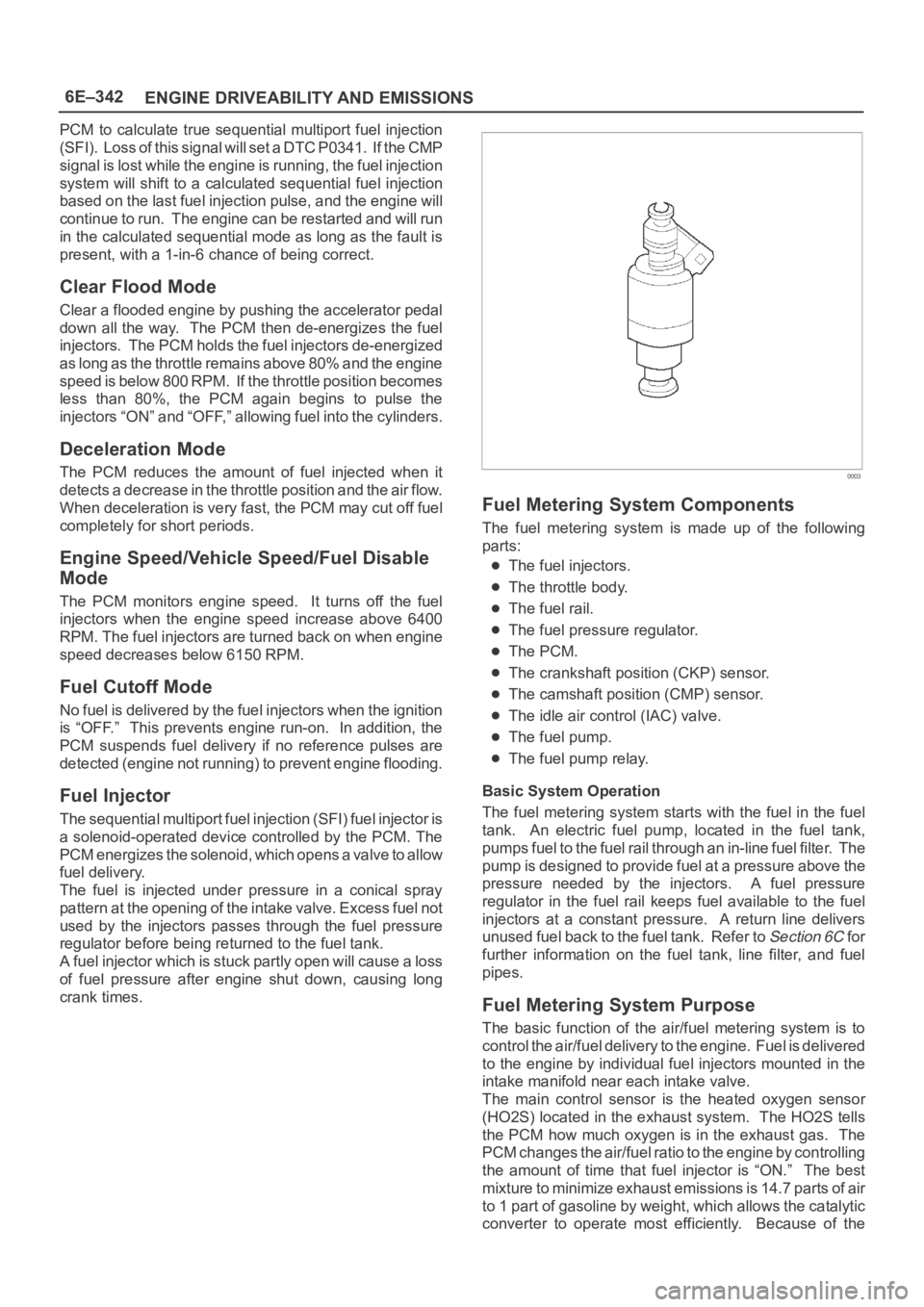
Fuel Injector
The sequential multiport fuel injection (SFI) fuel injector is
a solenoid-operated device controlled by the PCM. The
PCM energizes the solenoid, which opens a valve to allow
fuel delivery.
The fuel is injected under pressure in a conical spray
pattern at the opening of the intake valve. Excess fuel not
used by the injectors passes through the fuel pressure
regulator before being returned to the fuel tank.
A fuel injector which is stuck partly open will cause a loss
of fuel pressure after engine shut down, causing long
crank times.
0003
Fuel Metering System Components
The fuel metering system is made up of the following
parts:
The fuel injectors.
The throttle body.
The fuel rail.
The fuel pressure regulator.
The PCM.
The crankshaft position (CKP) sensor.
The camshaft position (CMP) sensor.
The idle air control (IAC) valve.
The fuel pump.
The fuel pump relay.
Basic System Operation
The fuel metering system starts with the fuel in the fuel
tank. An electric fuel pump, located in the fuel tank,
pumps fuel to the fuel rail through an in-line fuel filter. The
pump is designed to provide fuel at a pressure above the
pressure needed by the injectors. A fuel pressure
regulator in the fuel rail keeps fuel available to the fuel
injectors at a constant pressure. A return line delivers
unused fuel back to the fuel tank. Refer to
Section 6C f o r
further information on the fuel tank, line filter, and fuel
pipes.
Fuel Metering System Purpose
The basic function of the air/fuel metering system is to
control the air/fuel delivery to the engine. Fuel is delivered
to the engine by individual fuel injectors mounted in the
intake manifold near each intake valve.
The main control sensor is the heated oxygen sensor
(HO2S) located in the exhaust system. The HO2S tells
the PCM how much oxygen is in the exhaust gas. The
PCM changes the air/fuel ratio to the engine by controlling
the amount of time that fuel injector is “ON.” The best
mixture to minimize exhaust emissions is 14.7 parts of air
to 1 part of gasoline by weight, which allows the catalytic
converter to operate most efficiently. Because of the
Page 1460 of 6000
6E–343 ENGINE DRIVEABILITY AND EMISSIONS
constant measuring and adjusting of the air/fuel ratio, the
fuel injection system is called a “closed loop” system.
The PCM monitors signals from several sensors in order
to determine the fuel needs of the engine. Fuel is
delivered under one of several conditions called “modes.”
All modes are controlled by the PCM.
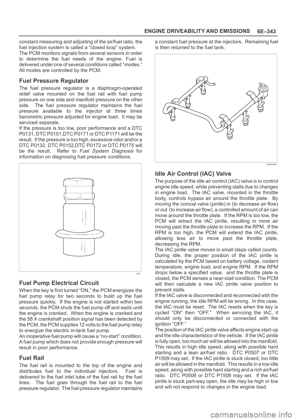
Fuel Pressure Regulator
The fuel pressure regulator is a diaphragm-operated
relief valve mounted on the fuel rail with fuel pump
pressure on one side and manifold pressure on the other
side. The fuel pressure regulator maintains the fuel
pressure available to the injector at three times
barometric pressure adjusted for engine load. It may be
serviced separate.
If the pressure is too low, poor performance and a DTC
P0131, DTC P0151,DTC P0171 or DTC P1171 will be the
result. If the pressure is too high, excessive odor and/or a
DTC P0132, DTC P0152,DTC P0172 or DTC P0175 will
be the result. Refer to
Fuel System Diagnosis for
information on diagnosing fuel pressure conditions.
0011
Fuel Pump Electrical Circuit
When the key is first turned “ON,” the PCM energizes the
fuel pump relay for two seconds to build up the fuel
pressure quickly. If the engine is not started within two
seconds, the PCM shuts the fuel pump off and waits until
the engine is cranked. When the engine is cranked and
the 58 X crankshaft position signal has been detected by
the PCM, the PCM supplies 12 volts to the fuel pump relay
to energize the electric in-tank fuel pump.
An inoperative fuel pump will cause a “no-start” condition.
A fuel pump which does not provide enough pressure will
result in poor performance.
Fuel Rail
The fuel rail is mounted to the top of the engine and
distributes fuel to the individual injectors. Fuel is
delivered to the fuel inlet tube of the fuel rail by the fuel
lines. The fuel goes through the fuel rail to the fuel
pressure regulator. The fuel pressure regulator maintainsa constant fuel pressure at the injectors. Remaining fuel
is then returned to the fuel tank.
055RW009
Idle Air Control (IAC) Valve
The purpose of the idle air control (IAC) valve is to control
engine idle speed, while preventing stalls due to changes
in engine load. The IAC valve, mounted in the throttle
body, controls bypass air around the throttle plate. By
moving the conical valve (pintle) in (to decrease air flow)
or out (to increase air flow), a controlled amount of air can
move around the throttle plate. If the RPM is too low, the
PCM will retract the IAC pintle, resulting in more air
moving past the throttle plate to increase the RPM. If the
RPM is too high, the PCM will extend the IAC pintle,
allowing less air to move past the throttle plate,
decreasing the RPM.
The IAC pintle valve moves in small steps called counts.
During idle, the proper position of the IAC pintle is
calculated by the PCM based on battery voltage, coolant
temperature, engine load, and engine RPM. If the RPM
drops below a specified value, and the throttle plate is
closed, the PCM senses a near-stall condition. The PCM
will then calculate a new IAC pintle valve position to
prevent stalls.
If the IAC valve is disconnected and reconnected with the
engine running, the idle RPM will be wrong. In this case,
the IAC must be reset. The IAC resets when the key is
cycled “ON” then “OFF.” When servicing the IAC, it
should only be disconnected or connected with the
ignition “OFF.”
The position of the IAC pintle valve affects engine start-up
and the idle characteristics of the vehicle. If the IAC pintle
is fully open, too much air will be allowed into the manifold.
This results in high idle speed, along with possible hard
starting and a lean air/fuel ratio. DTC P0507 or DTC
P1509 may set. If the IAC pintle is stuck closed, too little
air will be allowed in the manifold. This results in a low idle
speed, along with possible hard starting and a rich air/fuel
ratio. DTC P0506 or DTC P1508 may set. If the IAC
pintle is stuck part-way open, the idle may be high or low
and will not respond to changes in the engine load.