1998 OPEL FRONTERA Pressure fuel regulator
[x] Cancel search: Pressure fuel regulatorPage 1206 of 6000
6E–89 ENGINE DRIVEABILITY AND EMISSIONS
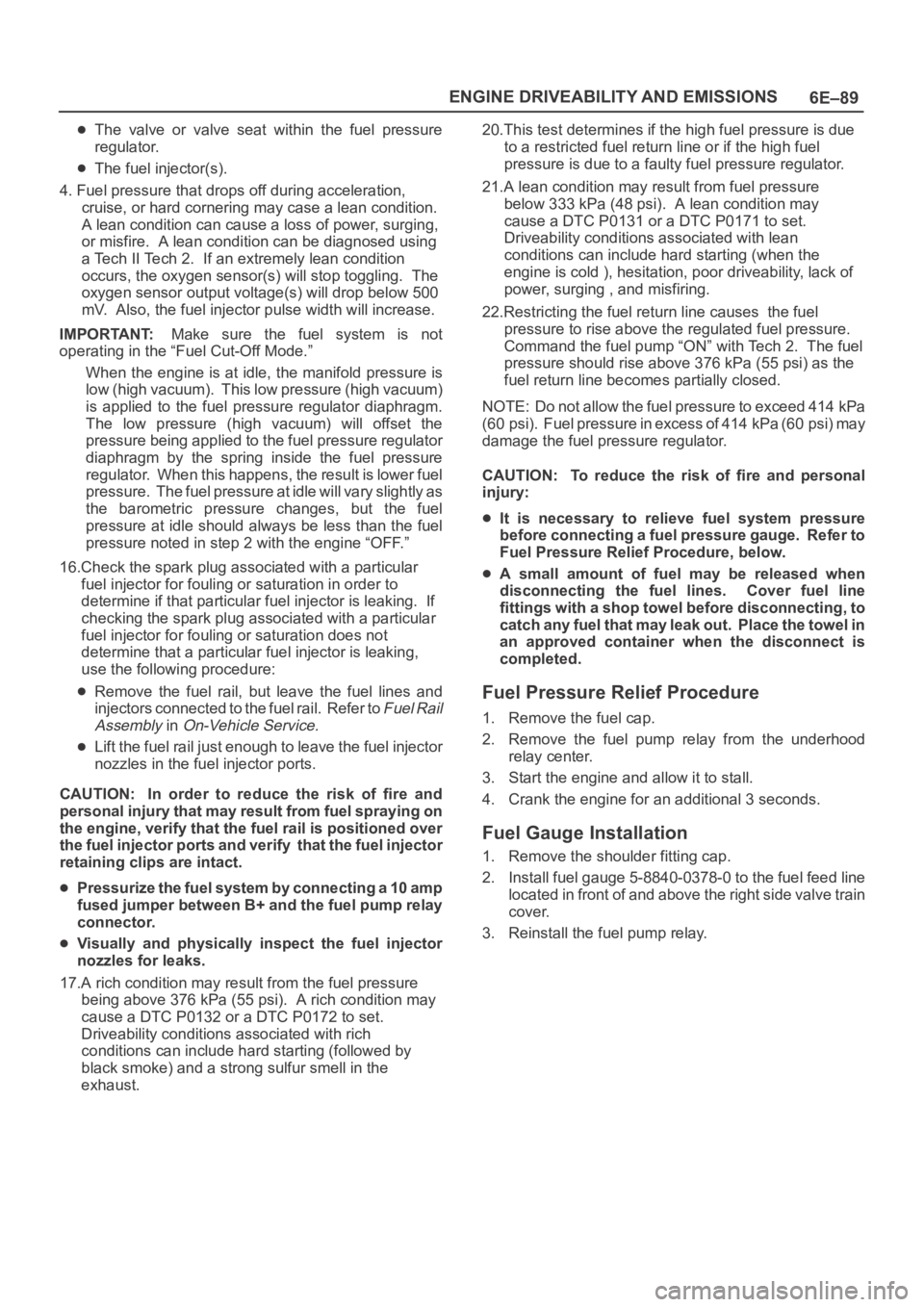
The valve or valve seat within the fuel pressure
regulator.
The fuel injector(s).
4. Fuel pressure that drops off during acceleration,
cruise, or hard cornering may case a lean condition.
A lean condition can cause a loss of power, surging,
or misfire. A lean condition can be diagnosed using
a Tech II Tech 2. If an extremely lean condition
occurs, the oxygen sensor(s) will stop toggling. The
oxygen sensor output voltage(s) will drop below 500
mV. Also, the fuel injector pulse width will increase.
IMPORTANT:Make sure the fuel system is not
operating in the “Fuel Cut-Off Mode.”
When the engine is at idle, the manifold pressure is
low (high vacuum). This low pressure (high vacuum)
is applied to the fuel pressure regulator diaphragm.
The low pressure (high vacuum) will offset the
pressure being applied to the fuel pressure regulator
diaphragm by the spring inside the fuel pressure
regulator. When this happens, the result is lower fuel
pressure. The fuel pressure at idle will vary slightly as
the barometric pressure changes, but the fuel
pressure at idle should always be less than the fuel
pressure noted in step 2 with the engine “OFF.”
16.Check the spark plug associated with a particular
fuel injector for fouling or saturation in order to
determine if that particular fuel injector is leaking. If
checking the spark plug associated with a particular
fuel injector for fouling or saturation does not
determine that a particular fuel injector is leaking,
use the following procedure:
Remove the fuel rail, but leave the fuel lines and
injectors connected to the fuel rail. Refer to
Fuel Rail
Assembly
in On-Vehicle Service.
Lift the fuel rail just enough to leave the fuel injector
nozzles in the fuel injector ports.
CAUTION: In order to reduce the risk of fire and
personal injury that may result from fuel spraying on
the engine, verify that the fuel rail is positioned over
the fuel injector ports and verify that the fuel injector
retaining clips are intact.
Pressurize the fuel system by connecting a 10 amp
fused jumper between B+ and the fuel pump relay
connector.
Visually and physically inspect the fuel injector
nozzles for leaks.
17.A rich condition may result from the fuel pressure
being above 376 kPa (55 psi). A rich condition may
cause a DTC P0132 or a DTC P0172 to set.
Driveability conditions associated with rich
conditions can include hard starting (followed by
black smoke) and a strong sulfur smell in the
exhaust.20.This test determines if the high fuel pressure is due
to a restricted fuel return line or if the high fuel
pressure is due to a faulty fuel pressure regulator.
21.A lean condition may result from fuel pressure
below 333 kPa (48 psi). A lean condition may
cause a DTC P0131 or a DTC P0171 to set.
Driveability conditions associated with lean
conditions can include hard starting (when the
engine is cold ), hesitation, poor driveability, lack of
power, surging , and misfiring.
22.Restricting the fuel return line causes the fuel
pressure to rise above the regulated fuel pressure.
Command the fuel pump “ON” with Tech 2. The fuel
pressure should rise above 376 kPa (55 psi) as the
fuel return line becomes partially closed.
NOTE: Do not allow the fuel pressure to exceed 414 kPa
( 6 0 p s i ) . F u e l p r e s s u r e i n e x c e s s o f 4 1 4 k P a ( 6 0 p s i ) m a y
damage the fuel pressure regulator.
CAUTION: To reduce the risk of fire and personal
injury:
It is necessary to relieve fuel system pressure
before connecting a fuel pressure gauge. Refer to
Fuel Pressure Relief Procedure, below.
A small amount of fuel may be released when
disconnecting the fuel lines. Cover fuel line
fittings with a shop towel before disconnecting, to
catch any fuel that may leak out. Place the towel in
an approved container when the disconnect is
completed.
Fuel Pressure Relief Procedure
1. Remove the fuel cap.
2. Remove the fuel pump relay from the underhood
relay center.
3. Start the engine and allow it to stall.
4. Crank the engine for an additional 3 seconds.
Fuel Gauge Installation
1. Remove the shoulder fitting cap.
2. Install fuel gauge 5-8840-0378-0 to the fuel feed line
located in front of and above the right side valve train
cover.
3. Reinstall the fuel pump relay.
Page 1207 of 6000
6E–90
ENGINE DRIVEABILITY AND EMISSIONS
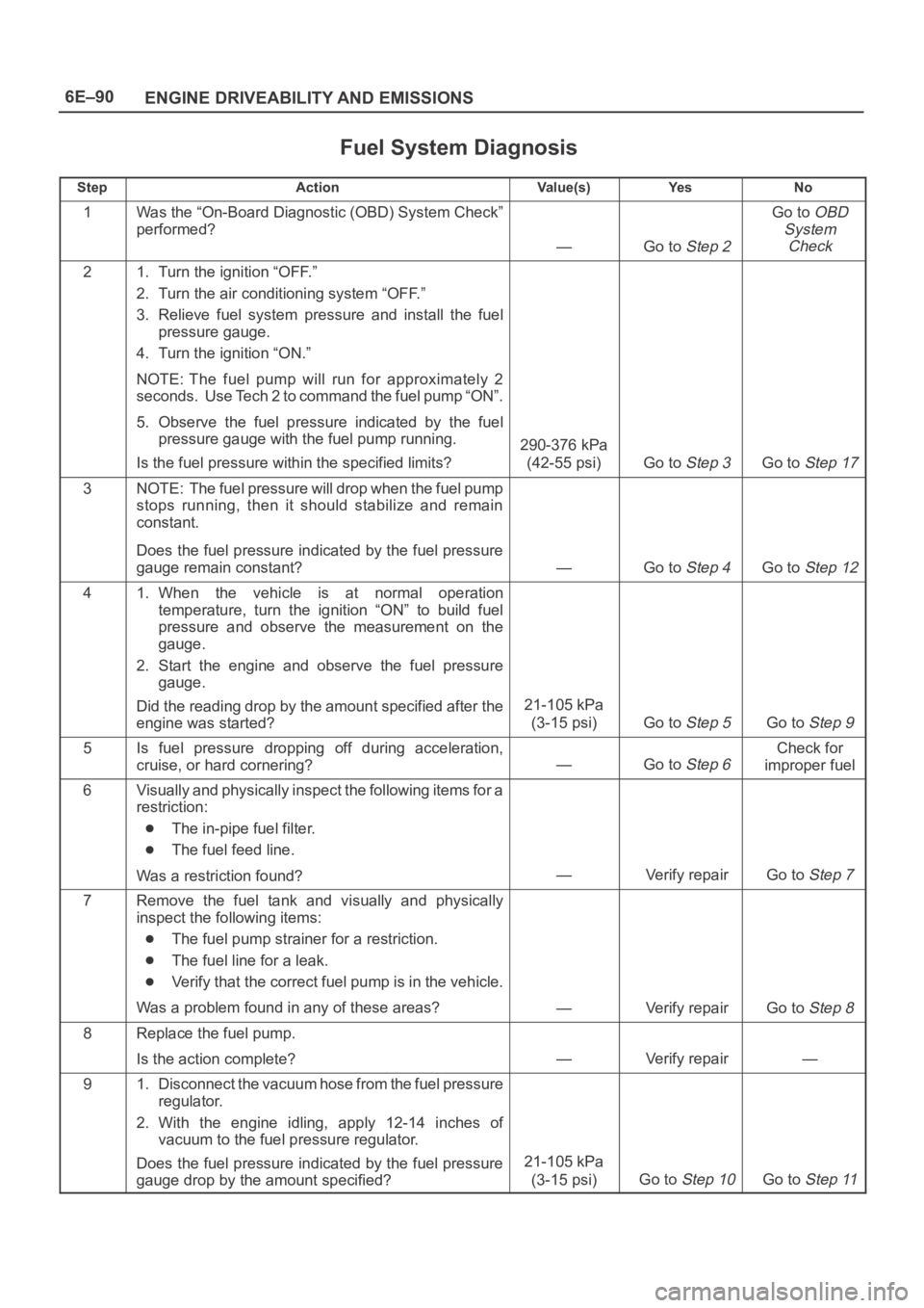
Fuel System Diagnosis
StepActionVa l u e ( s )Ye sNo
1Was the “On-Board Diagnostic (OBD) System Check”
performed?
—Go to Step 2
Go to OBD
System
Check
21. Turn the ignition “OFF.”
2. Turn the air conditioning system “OFF.”
3. Relieve fuel system pressure and install the fuel
pressure gauge.
4. Turn the ignition “ON.”
NOTE: The fuel pump will run for approximately 2
seconds. Use Tech 2 to command the fuel pump “ON”.
5. Observe the fuel pressure indicated by the fuel
pressure gauge with the fuel pump running.
Is the fuel pressure within the specified limits?
290-376 kPa
(42-55 psi)
Go to Step 3Go to Step 17
3NOTE: The fuel pressure will drop when the fuel pump
stops running, then it should stabilize and remain
constant.
Does the fuel pressure indicated by the fuel pressure
gauge remain constant?
—Go to Step 4Go to Step 12
41. When the vehicle is at normal operation
temperature, turn the ignition “ON” to build fuel
pressure and observe the measurement on the
gauge.
2. Start the engine and observe the fuel pressure
gauge.
Did the reading drop by the amount specified after the
engine was started?
21-105 kPa
(3-15 psi)
Go to Step 5Go to Step 9
5Is fuel pressure dropping off during acceleration,
cruise, or hard cornering?
—Go to Step 6
Check for
improper fuel
6Visually and physically inspect the following items for a
restriction:
The in-pipe fuel filter.
The fuel feed line.
Was a restriction found?
—Verify repairGo to Step 7
7Remove the fuel tank and visually and physically
inspect the following items:
The fuel pump strainer for a restriction.
The fuel line for a leak.
Verify that the correct fuel pump is in the vehicle.
Was a problem found in any of these areas?
—Verify repairGo to Step 8
8Replace the fuel pump.
Is the action complete?
—Verify repair—
91. Disconnect the vacuum hose from the fuel pressure
regulator.
2. With the engine idling, apply 12-14 inches of
vacuum to the fuel pressure regulator.
Does the fuel pressure indicated by the fuel pressure
gauge drop by the amount specified?
21-105 kPa
(3-15 psi)
Go to Step 10Go to Step 11
Page 1208 of 6000
6E–91 ENGINE DRIVEABILITY AND EMISSIONS
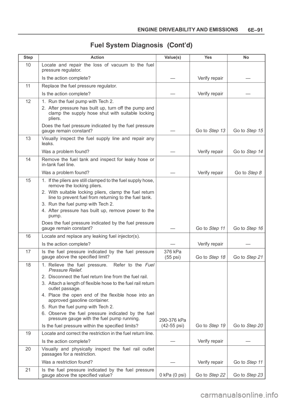
Fuel System Diagnosis
StepNo Ye s Va l u e ( s ) Action
10Locate and repair the loss of vacuum to the fuel
pressure regulator.
Is the action complete?
—Verify repair—
11Replace the fuel pressure regulator.
Is the action complete?
—Verify repair—
121. Run the fuel pump with Tech 2.
2. After pressure has built up, turn off the pump and
clamp the supply hose shut with suitable locking
pliers.
Does the fuel pressure indicated by the fuel pressure
gauge remain constant?
—Go to Step 13Go to Step 15
13Visually inspect the fuel supply line and repair any
leaks.
Was a problem found?
—Verify repairGo to Step 14
14Remove the fuel tank and inspect for leaky hose or
in-tank fuel line.
Was a problem found?
—Verify repairGo to Step 8
151. If the pliers are still clamped to the fuel supply hose,
remove the locking pliers.
2. With suitable locking pliers, clamp the fuel return
line to prevent fuel from returning to the fuel tank.
3. Run the fuel pump with Tech 2.
4. After pressure has built up, remove power to the
pump.
Does the fuel pressure indicated by the fuel pressure
gauge remain constant?
—Go to Step 11Go to Step 16
16Locate and replace any leaking fuel injector(s).
Is the action complete?
—Verify repair—
17Is the fuel pressure indicated by the fuel pressure
gauge above the specified limit?376 kPa
(55 psi)
Go to Step 18Go to Step 21
181. Relieve the fuel pressure. Refer to the Fuel
Pressure Relief.
2. Disconnect the fuel return line from the fuel rail.
3. Attach a length of flexible hose to the fuel rail return
outlet passage.
4. Place the open end of the flexible hose into an
approved gasoline container.
5. Run the fuel pump with Tech 2.
6. Observe the fuel pressure indicated by the fuel
pressure gauge with the fuel pump running.
Is the fuel pressure within the specified limits?
290-376 kPa
(42-55 psi)
Go to Step 19Go to Step 20
19Locate and correct the restriction in the fuel return line.
Is the action complete?
—Verify repair—
20Visually and physically inspect the fuel rail outlet
passages for a restriction.
Was a restriction found?
—Verify repairGo to Step 11
21Is the fuel pressure indicated by the fuel pressure
gauge above the specified value?
0kPa (0psi)Go to Step 22Go to Step 23
Page 1259 of 6000
6E–142
ENGINE DRIVEABILITY AND EMISSIONS
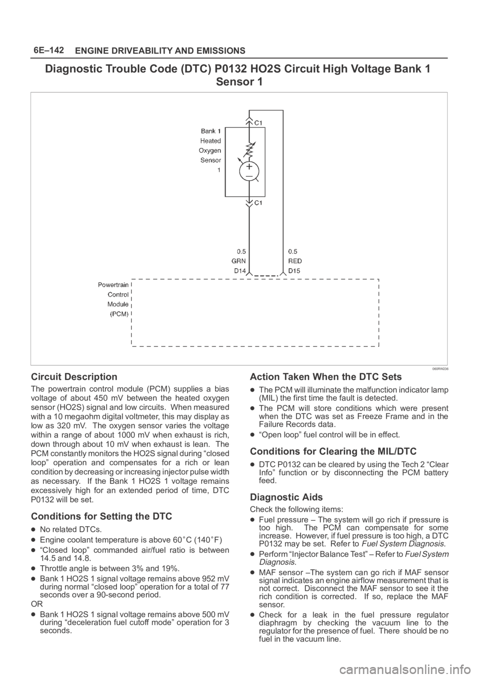
Diagnostic Trouble Code (DTC) P0132 HO2S Circuit High Voltage Bank 1
Sensor 1
060RW236
Circuit Description
The powertrain control module (PCM) supplies a bias
voltage of about 450 mV between the heated oxygen
sensor (HO2S) signal and low circuits. When measured
with a 10 megaohm digital voltmeter, this may display as
low as 320 mV. The oxygen sensor varies the voltage
within a range of about 1000 mV when exhaust is rich,
down through about 10 mV when exhaust is lean. The
PCM constantly monitors the HO2S signal during “closed
loop” operation and compensates for a rich or lean
condition by decreasing or increasing injector pulse width
as necessary. If the Bank 1 HO2S 1 voltage remains
excessively high for an extended period of time, DTC
P0132 will be set.
Conditions for Setting the DTC
No related DTCs.
Engine coolant temperature is above 60C (140F)
“Closed loop” commanded air/fuel ratio is between
14.5 and 14.8.
Throttle angle is between 3% and 19%.
Bank 1 HO2S 1 signal voltage remains above 952 mV
during normal “closed loop” operation for a total of 77
seconds over a 90-second period.
OR
Bank 1 HO2S 1 signal voltage remains above 500 mV
during “deceleration fuel cutoff mode” operation for 3
seconds.
Action Taken When the DTC Sets
The PCM will illuminate the malfunction indicator lamp
(MIL) the first time the fault is detected.
The PCM will store conditions which were present
when the DTC was set as Freeze Frame and in the
Failure Records data.
“Open loop” fuel control will be in effect.
Conditions for Clearing the MIL/DTC
DTC P0132 can be cleared by using the Tech 2 “Clear
Info” function or by disconnecting the PCM battery
feed.
Diagnostic Aids
Check the following items:
Fuel pressure – The system will go rich if pressure is
too high. The PCM can compensate for some
increase. However, if fuel pressure is too high, a DTC
P0132 may be set. Refer to
Fuel System Diagnosis.
Perform “Injector Balance Test” – Refer to Fuel System
Diagnosis.
MAF sensor –The system can go rich if MAF sensor
signal indicates an engine airflow measurement that is
not correct. Disconnect the MAF sensor to see it the
rich condition is corrected. If so, replace the MAF
sensor.
Check for a leak in the fuel pressure regulator
diaphragm by checking the vacuum line to the
regulator for the presence of fuel. There should be no
fuel in the vacuum line.
Page 1269 of 6000
6E–152
ENGINE DRIVEABILITY AND EMISSIONS
MAF sensor – The system can go rich if the MAF
sensor signal indicates an engine airflow
measurement that is not correct. Disconnect the MAF
sensor to see if rich condition is corrected. If so,
replace MAF sensor.
Check for leaking fuel pressure regulator diaphragm by
checking vacuum line to regulator for the presence of
fuel. There should be no fuel in the vacuum line.
TP sensor – An intermittent TP sensor output will
cause the system to go rich, due to a false indication
of the engine accelerating.
Shorted Heated Oxygen Sensor (HO2S)– If the HO2S
is internally shorted, the HO2S voltage displayed on
Tech 2 will be over 1 volt. Try disconnecting the
affected HO2S with the key “ON,” engine “OFF.” If the
displayed HO2S voltage changes from over 1000 mV
to around 450mV, replace the HO2S. Silicon
contamination of the HO2S can cause a high HO2S
voltage to be indicated. This condition is indicated by
powdery white deposit on the portion of the HO2S
exposed to the exhaust stream. If contamination is
noticed, replace the affected HO2S.
Open HO2S Signal Circuit of Faulty HO2S– A poor
connection or open in the HO2S signal circuit can
cause the DTC to set during deceleration fuel mode.An HO2S which is faulty and not allowing a full voltage
switch between the rich and lean thresholds can also
cause the condition. Operate the vehicle while
monitoring the HO2S voltage with Tech 2. If the HO2S
is limited within a range between 300 mV to 600 mV,
check the HO2S signal circuit wiring and associated
terminal connections.
If none of the above conditions are present, replace the
affected HO2S.
Test Description
Number(s) below refer to the step number(s) on the
Diagnostic Chart.
3. DTC P0152 failing during deceleration fuel cutoff
mode operation may indicate a condition described
in the “Diagnostic Aids” above. If the DTC P0152
test passes while the Failure Records conditions are
being duplicated, an intermittent condition is
indicated.
Reviewing the Failure Records vehicle mileage since the
diagnostic test last failed may help determine how often
the condition that caused the DTC to be set occurs. This
may assist in diagnosing the condition.
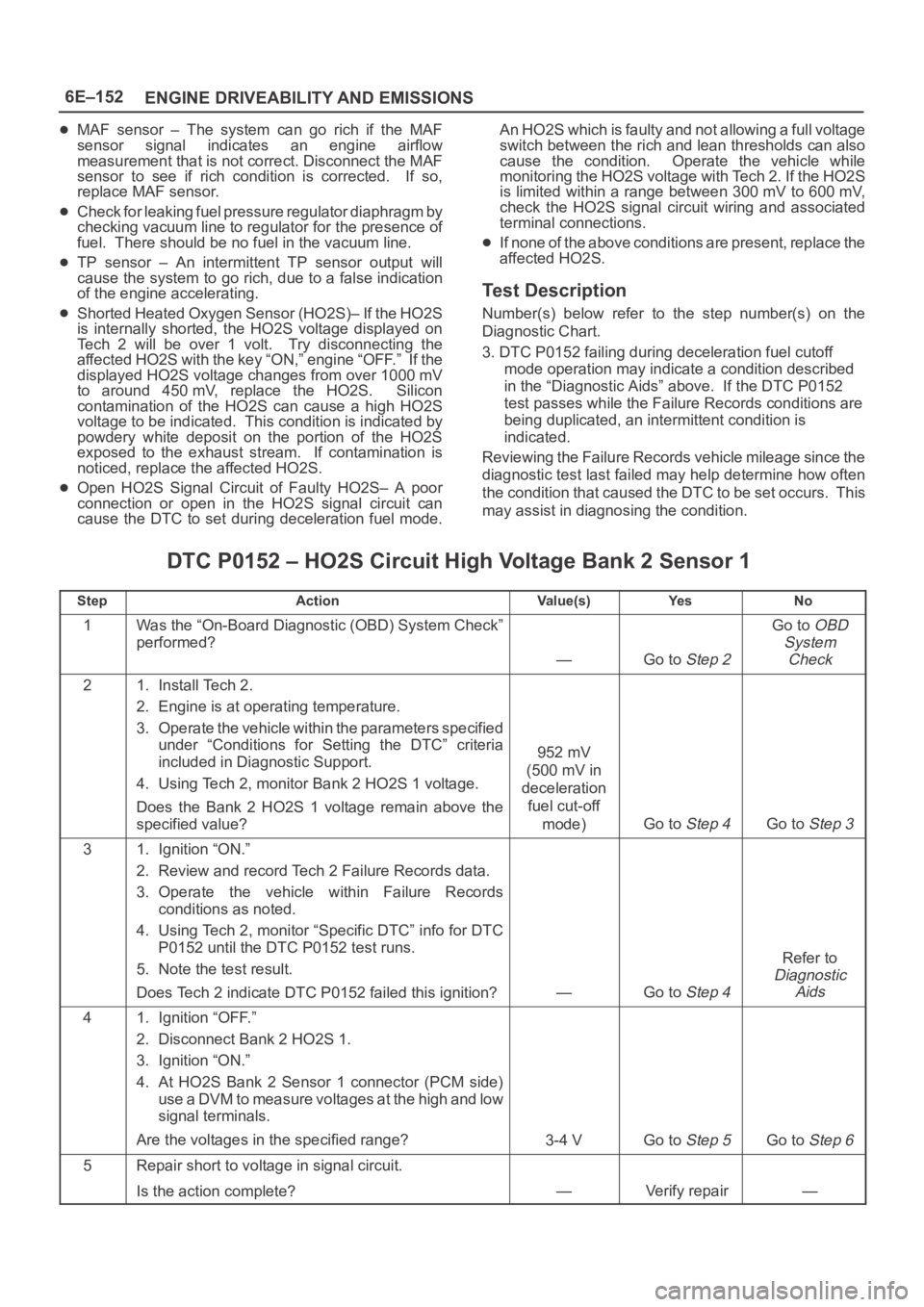
DTC P0152 – HO2S Circuit High Voltage Bank 2 Sensor 1
StepActionVa l u e ( s )Ye sNo
1Was the “On-Board Diagnostic (OBD) System Check”
performed?
—Go to Step 2
Go to OBD
System
Check
21. Install Tech 2.
2. Engine is at operating temperature.
3. Operate the vehicle within the parameters specified
under “Conditions for Setting the DTC” criteria
included in Diagnostic Support.
4. Using Tech 2, monitor Bank 2 HO2S 1 voltage.
Does the Bank 2 HO2S 1 voltage remain above the
specified value?
952 mV
(500 mV in
deceleration
fuel cut-off
mode)
Go to Step 4Go to Step 3
31. Ignition “ON.”
2. Review and record Tech 2 Failure Records data.
3. Operate the vehicle within Failure Records
conditions as noted.
4. Using Tech 2, monitor “Specific DTC” info for DTC
P0152 until the DTC P0152 test runs.
5. Note the test result.
Does Tech 2 indicate DTC P0152 failed this ignition?
—Go to Step 4
Refer to
Diagnostic
Aids
41. Ignition “OFF.”
2. Disconnect Bank 2 HO2S 1.
3. Ignition “ON.”
4. At HO2S Bank 2 Sensor 1 connector (PCM side)
use a DVM to measure voltages at the high and low
signal terminals.
Are the voltages in the specified range?
3-4 VGo to Step 5Go to Step 6
5Repair short to voltage in signal circuit.
Is the action complete?
—Verify repair—
Page 1278 of 6000
6E–161 ENGINE DRIVEABILITY AND EMISSIONS
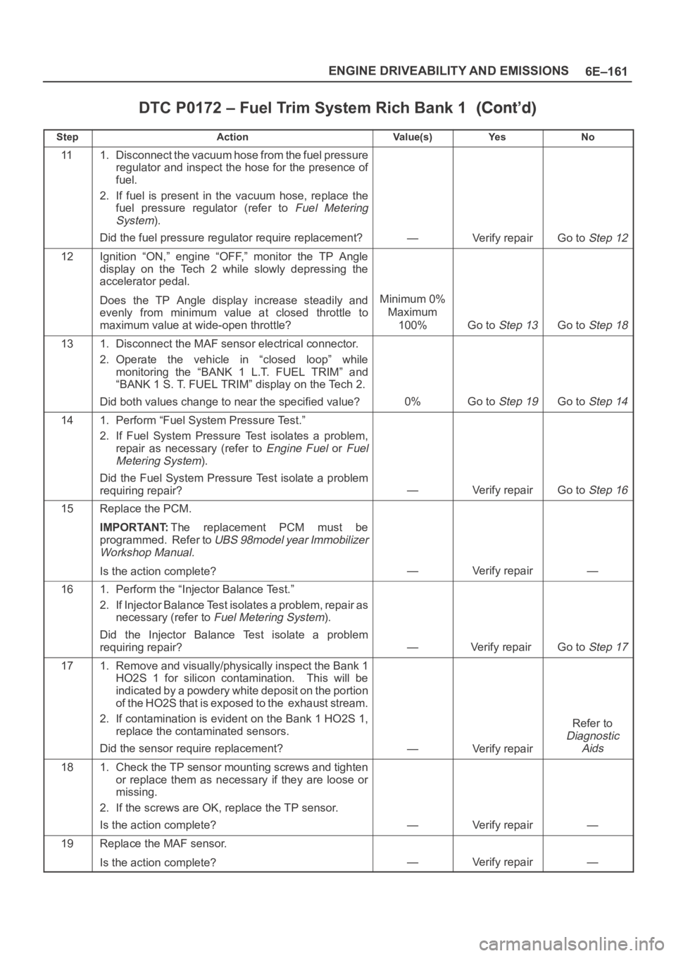
DTC P0172 – Fuel Trim System Rich Bank 1
StepNo Ye s Va l u e ( s ) Action
111. Disconnect the vacuum hose from the fuel pressure
regulator and inspect the hose for the presence of
fuel.
2. If fuel is present in the vacuum hose, replace the
fuel pressure regulator (refer to
Fuel Metering
System
).
Did the fuel pressure regulator require replacement?
—Verify repairGo to Step 12
12Ignition “ON,” engine “OFF,” monitor the TP Angle
display on the Tech 2 while slowly depressing the
accelerator pedal.
Does the TP Angle display increase steadily and
evenly from minimum value at closed throttle to
maximum value at wide-open throttle?
Minimum 0%
Maximum
100%
Go to Step 13Go to Step 18
131. Disconnect the MAF sensor electrical connector.
2. Operate the vehicle in “closed loop” while
monitoring the “BANK 1 L.T. FUEL TRIM” and
“BANK 1 S. T. FUEL TRIM” display on the Tech 2.
Did both values change to near the specified value?
0%Go to Step 19Go to Step 14
141. Perform “Fuel System Pressure Test.”
2. If Fuel System Pressure Test isolates a problem,
repair as necessary (refer to
Engine Fuel or Fuel
Metering System
).
Did the Fuel System Pressure Test isolate a problem
requiring repair?
—Verify repairGo to Step 16
15Replace the PCM.
IMPORTANT:The replacement PCM must be
programmed. Refer to
UBS 98model year Immobilizer
Workshop Manual.
Is the action complete?—Verify repair—
161. Perform the “Injector Balance Test.”
2. If Injector Balance Test isolates a problem, repair as
necessary (refer to
Fuel Metering System).
Did the Injector Balance Test isolate a problem
requiring repair?
—Verify repair Go to Step 17
171. Remove and visually/physically inspect the Bank 1
HO2S 1 for silicon contamination. This will be
indicated by a powdery white deposit on the portion
of the HO2S that is exposed to the exhaust stream.
2. If contamination is evident on the Bank 1 HO2S 1,
replace the contaminated sensors.
Did the sensor require replacement?
—Verify repair
Refer to
Diagnostic
Aids
181. Check the TP sensor mounting screws and tighten
or replace them as necessary if they are loose or
missing.
2. If the screws are OK, replace the TP sensor.
Is the action complete?
—Verify repair—
19Replace the MAF sensor.
Is the action complete?
—Verify repair—
Page 1286 of 6000
6E–169 ENGINE DRIVEABILITY AND EMISSIONS
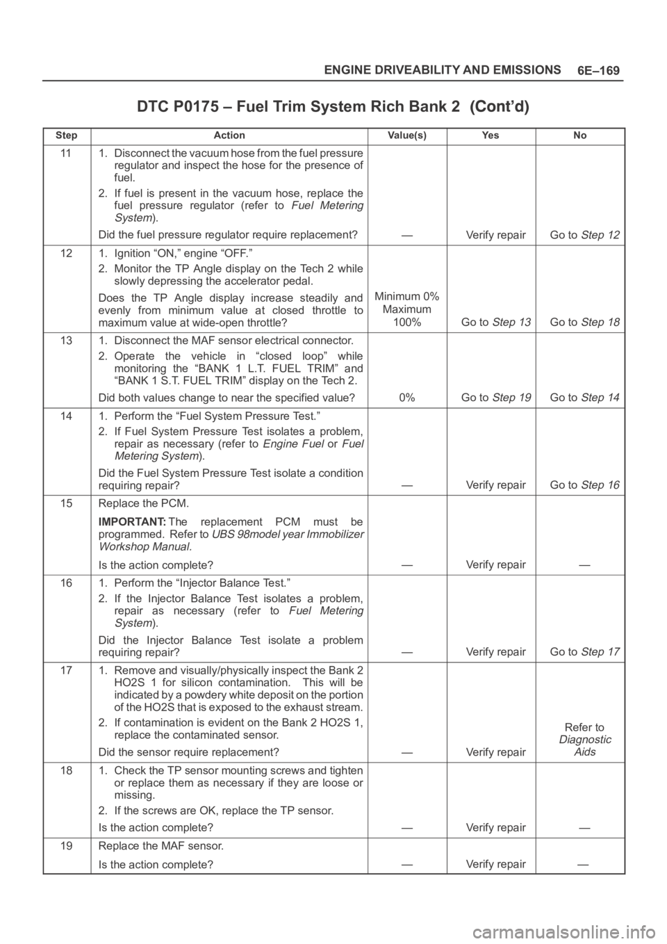
DTC P0175 – Fuel Trim System Rich Bank 2
StepNo Ye s Va l u e ( s ) Action
111. Disconnect the vacuum hose from the fuel pressure
regulator and inspect the hose for the presence of
fuel.
2. If fuel is present in the vacuum hose, replace the
fuel pressure regulator (refer to
Fuel Metering
System
).
Did the fuel pressure regulator require replacement?
—Verify repairGo to Step 12
121. Ignition “ON,” engine “OFF.”
2. Monitor the TP Angle display on the Tech 2 while
slowly depressing the accelerator pedal.
Does the TP Angle display increase steadily and
evenly from minimum value at closed throttle to
maximum value at wide-open throttle?
Minimum 0%
Maximum
100%
Go to Step 13Go to Step 18
131. Disconnect the MAF sensor electrical connector.
2. Operate the vehicle in “closed loop” while
monitoring the “BANK 1 L.T. FUEL TRIM” and
“BANK 1 S.T. FUEL TRIM” display on the Tech 2.
Did both values change to near the specified value?
0%Go to Step 19Go to Step 14
141. Perform the “Fuel System Pressure Test.”
2. If Fuel System Pressure Test isolates a problem,
repair as necessary (refer to
Engine Fuel or Fuel
Metering System
).
Did the Fuel System Pressure Test isolate a condition
requiring repair?
—Verify repairGo to Step 16
15Replace the PCM.
IMPORTANT:The replacement PCM must be
programmed. Refer to
UBS 98model year Immobilizer
Workshop Manual.
Is the action complete?—Verify repair—
161. Perform the “Injector Balance Test.”
2. If the Injector Balance Test isolates a problem,
repair as necessary (refer to
Fuel Metering
System
).
Did the Injector Balance Test isolate a problem
requiring repair?
—Verify repairGo to Step 17
171. Remove and visually/physically inspect the Bank 2
HO2S 1 for silicon contamination. This will be
indicated by a powdery white deposit on the portion
of the HO2S that is exposed to the exhaust stream.
2. If contamination is evident on the Bank 2 HO2S 1,
replace the contaminated sensor.
Did the sensor require replacement?
—Verify repair
Refer to
Diagnostic
Aids
181. Check the TP sensor mounting screws and tighten
or replace them as necessary if they are loose or
missing.
2. If the screws are OK, replace the TP sensor.
Is the action complete?
—Verify repair—
19Replace the MAF sensor.
Is the action complete?
—Verify repair—
Page 1363 of 6000
6E–246
ENGINE DRIVEABILITY AND EMISSIONS
amounts of fuel at idle, but may not be able to supply
enough fuel during heavy acceleration.
Water or alcohol in the fuel may cause low HO2S
voltage during acceleration.
Check for faulty or plugged fuel injector(s).
Check for low fuel.
Test Description
Number(s) below refer to the step number(s) on the
Diagnostic Chart.4. When the engine is idling or at steady cruise, the
HO2S voltage should vary from between
approximately 100 mV to 900 mV. It is possible to
measure a satisfactory fuel pressure at idle even
though the pressure may drop at high flow
requirements. It may be necessary to watch fuel
pressure at high engine load.
5. Wrap a shop towel around the fuel pressure
connector to absorb any small amount of fuel
leakage that may occur when installing gauge.
Ignition “ON,” pump pressure should be 280-320
kPa.
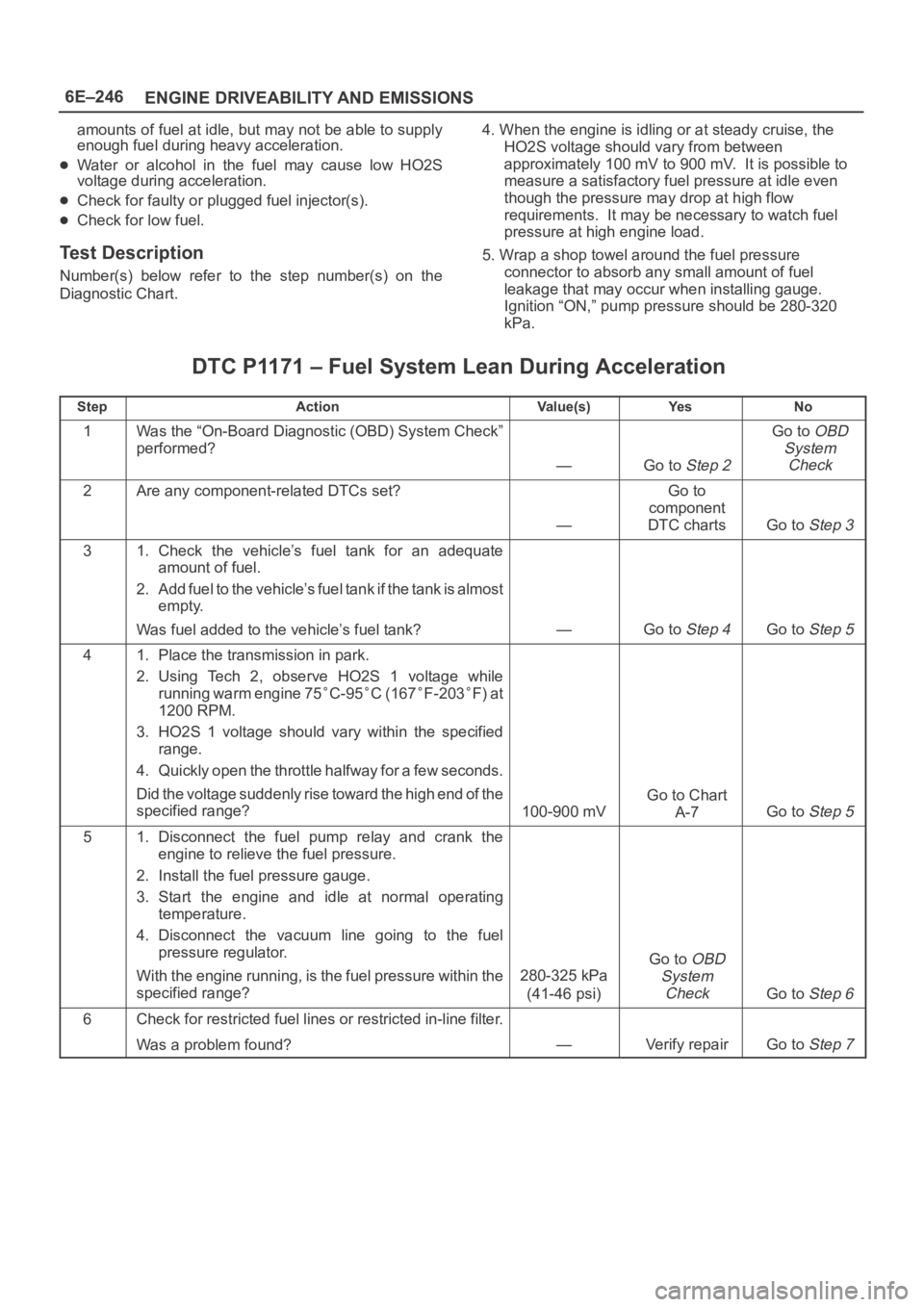
DTC P1171 – Fuel System Lean During Acceleration
StepActionVa l u e ( s )Ye sNo
1Was the “On-Board Diagnostic (OBD) System Check”
performed?
—Go to Step 2
Go to OBD
System
Check
2Are any component-related DTCs set?
—
Go to
component
DTC charts
Go to Step 3
31. Check the vehicle’s fuel tank for an adequate
amount of fuel.
2. Add fuel to the vehicle’s fuel tank if the tank is almost
empty.
Was fuel added to the vehicle’s fuel tank?
—Go to Step 4Go to Step 5
41. Place the transmission in park.
2. Using Tech 2, observe HO2S 1 voltage while
running warm engine 75
C-95C (167F-203F) at
1200 RPM.
3. HO2S 1 voltage should vary within the specified
range.
4. Quickly open the throttle halfway for a few seconds.
Did the voltage suddenly rise toward the high end of the
specified range?
100-900 mV
Go to Chart
A-7
Go to Step 5
51. Disconnect the fuel pump relay and crank the
engine to relieve the fuel pressure.
2. Install the fuel pressure gauge.
3. Start the engine and idle at normal operating
temperature.
4. Disconnect the vacuum line going to the fuel
pressure regulator.
With the engine running, is the fuel pressure within the
specified range?
280-325 kPa
(41-46 psi)
Go to OBD
System
Check
Go to Step 6
6Check for restricted fuel lines or restricted in-line filter.
Was a problem found?
—Verify repairGo to Step 7