Page 5674 of 6000
ENGINE SPEED CONTROL 6H – 1
ENGINE SPEED CONTROL
CONTENTS
General Description . . . . . . . . . . . . . . . . . . 6H–2 Engine Speed Control . . . . . . . . . . . . . . . . . 6H–3
Page 5675 of 6000

6H – 2 ENGINE SPEED CONTROL
GENERAL DESCRIPTION
3For A/T
1For M/T
2
1
101RW012
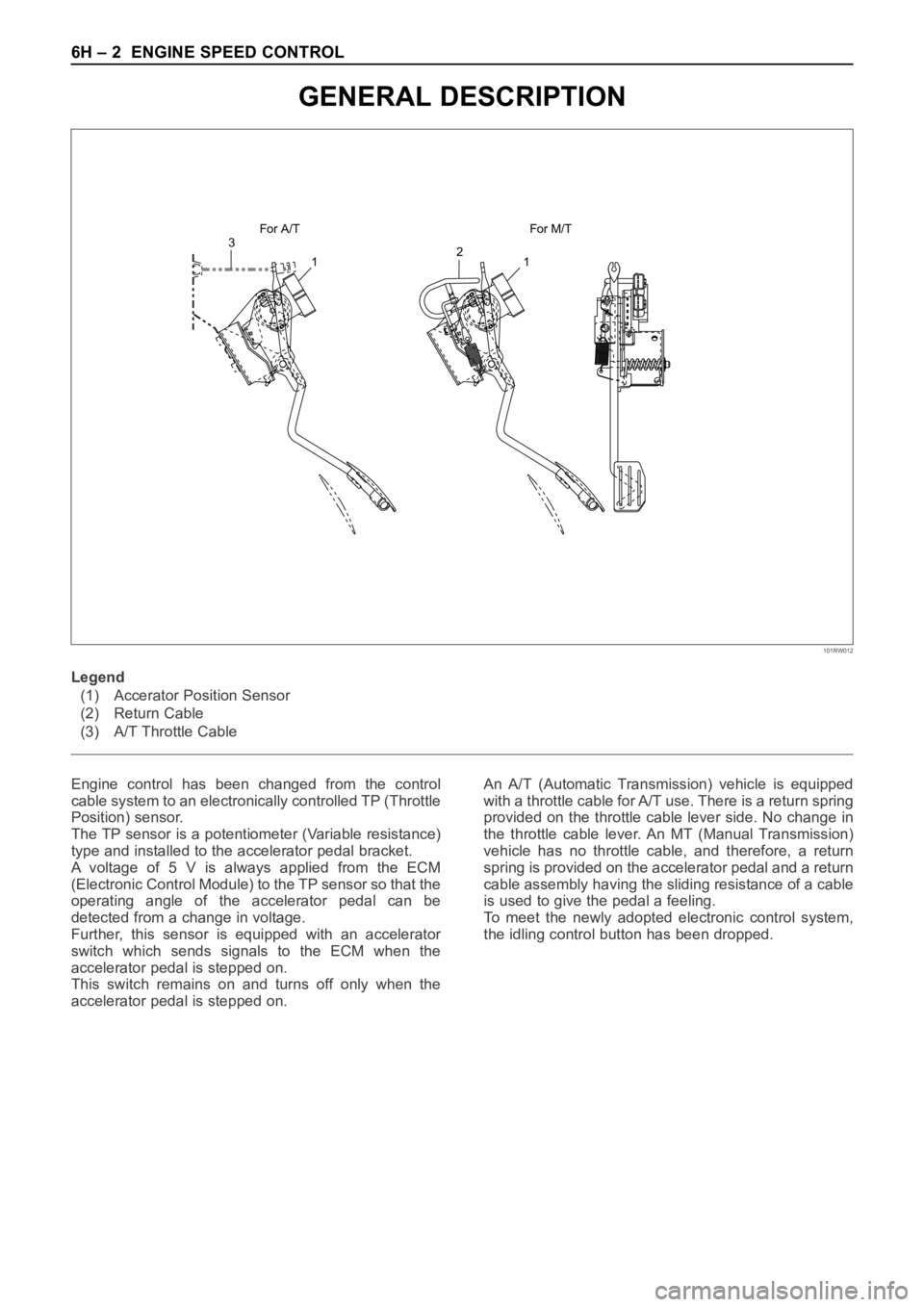
Engine control has been changed from the control
cable system to an electronically controlled TP (Throttle
Position) sensor.
The TP sensor is a potentiometer (Variable resistance)
type and installed to the accelerator pedal bracket.
A voltage of 5 V is always applied from the ECM
(Electronic Control Module) to the TP sensor so that the
operating angle of the accelerator pedal can be
detected from a change in voltage.
Further, this sensor is equipped with an accelerator
switch which sends signals to the ECM when the
accelerator pedal is stepped on.
This switch remains on and turns off only when the
accelerator pedal is stepped on.An A/T (Automatic Transmission) vehicle is equipped
with a throttle cable for A/T use. There is a return spring
provided on the throttle cable lever side. No change in
the throttle cable lever. An MT (Manual Transmission)
vehicle has no throttle cable, and therefore, a return
spring is provided on the accelerator pedal and a return
cable assembly having the sliding resistance of a cable
is used to give the pedal a feeling.
To meet the newly adopted electronic control system,
the idling control button has been dropped. Legend
(1) Accerator Position Sensor
(2) Return Cable
(3) A/T Throttle Cable
Page 5676 of 6000
ENGINE SPEED CONTROL 6H – 3
REMOVAL
1. For vehicle with MT
1) Remove harness connector from accelerator
pedal sensor.
2) Remove accelerator pedal assembly from
chassis.
2. For vehicle with A/T
1) Remove A/T control cable from accelerator
pedal assembly.
2) Remove harness connector from accelerator
pedal sensor.
3) Remove accelerator pedal assembly from
chassis.
INSPECTION AND REPAIR
1. Check moving condition of accelerator pedal, if not
smooth working, apply oil to the pivot etc.
2. Check tightening condition of accelerator sensor, if
not completely tightened, it should be tightened
additionally.
INSTALLATION
The installation for both MT and A/T vehicles follows the
reverse manner of removal.
ENGINE SPEED CONTROL
Page 5681 of 6000
6J – 4 INDUCTION
TURBOCHARGER
REMOVAL
2. Drain engine coolant.
3. Remove air cleaner cover and air duct.
4. Remove intercooler assembly.
Refer to “Intercooler” in this manual.
5. Remove water pipe from water inlet of
turbocharger.
6. Remove oil pipe.
1) Remove fixing bolts from oil inlet of turbocharger
then remove oil pipe.
2) Plug open port of turbocharger to prevent
foreign materials from entering the turbocharger.
7. Remove oil drain pipe from turbocharger.
8. Remove water outlet pipe from turbocharger.
9. Remove heat protector.
10. Remove exhaust valve assembly.
11. Remove turbocharger fixing nuts from exhaust
manifold then remove turbocharger assembly.
9875 63
21
4
Legend
(1) Exhaust Manifold
(2) Gasket
(3) Turbocharger Assembly
(4) Water Hose(5) Water Hose
(6) Heat Protector
(7) Oil Pipe
(8) Oil Pipe
(9) Gasket
025RW023
036RW006
Page 5682 of 6000

INDUCTION 6J – 5
INSPECTION AND REPAIR
Make the necessary adjustments, repairs and part
replacements if excessive wear or damage is
discovered during inspection.
Minor servicing operations are described in this section.
Contact the nearest IHI SERVICE FACILITY for major
repairs and maintenance.
Refer to IHI SERVICE NETWORK at the end of this
section for the location of your area’s IHI SERVICE
FACILITY.
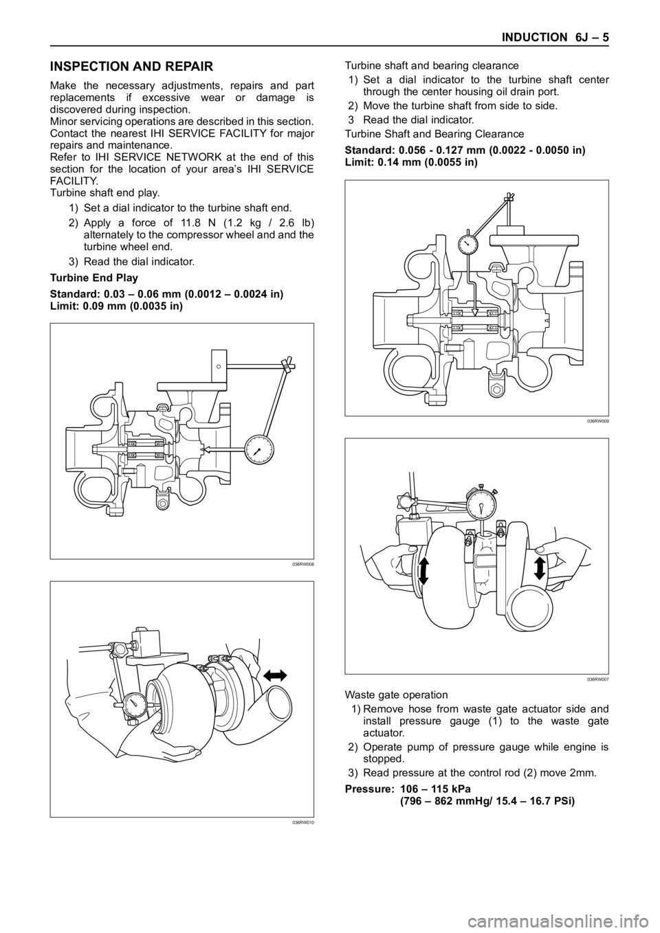
Turbine shaft end play.
1) Set a dial indicator to the turbine shaft end.
2) Apply a force of 11.8 N (1.2 kg / 2.6 lb)
alternately to the compressor wheel and and the
turbine wheel end.
3) Read the dial indicator.
Turbine End Play
Standard: 0.03 – 0.06 mm (0.0012 – 0.0024 in)
Limit: 0.09 mm (0.0035 in)Turbine shaft and bearing clearance
1) Set a dial indicator to the turbine shaft center
through the center housing oil drain port.
2) Move the turbine shaft from side to side.
3 Read the dial indicator.
Turbine Shaft and Bearing Clearance
Standard: 0.056 - 0.127 mm (0.0022 - 0.0050 in)
Limit: 0.14 mm (0.0055 in)
Waste gate operation
1) Remove hose from waste gate actuator side and
install pressure gauge (1) to the waste gate
actuator.
2) Operate pump of pressure gauge while engine is
stopped.
3) Read pressure at the control rod (2) move 2mm.
Pressure: 106 – 115 kPa
(796 – 862 mmHg/ 15.4 – 16.7 PSi)
036RW008
036RW010
036RW009
036RW007
Page 5683 of 6000

6J – 6 INDUCTION
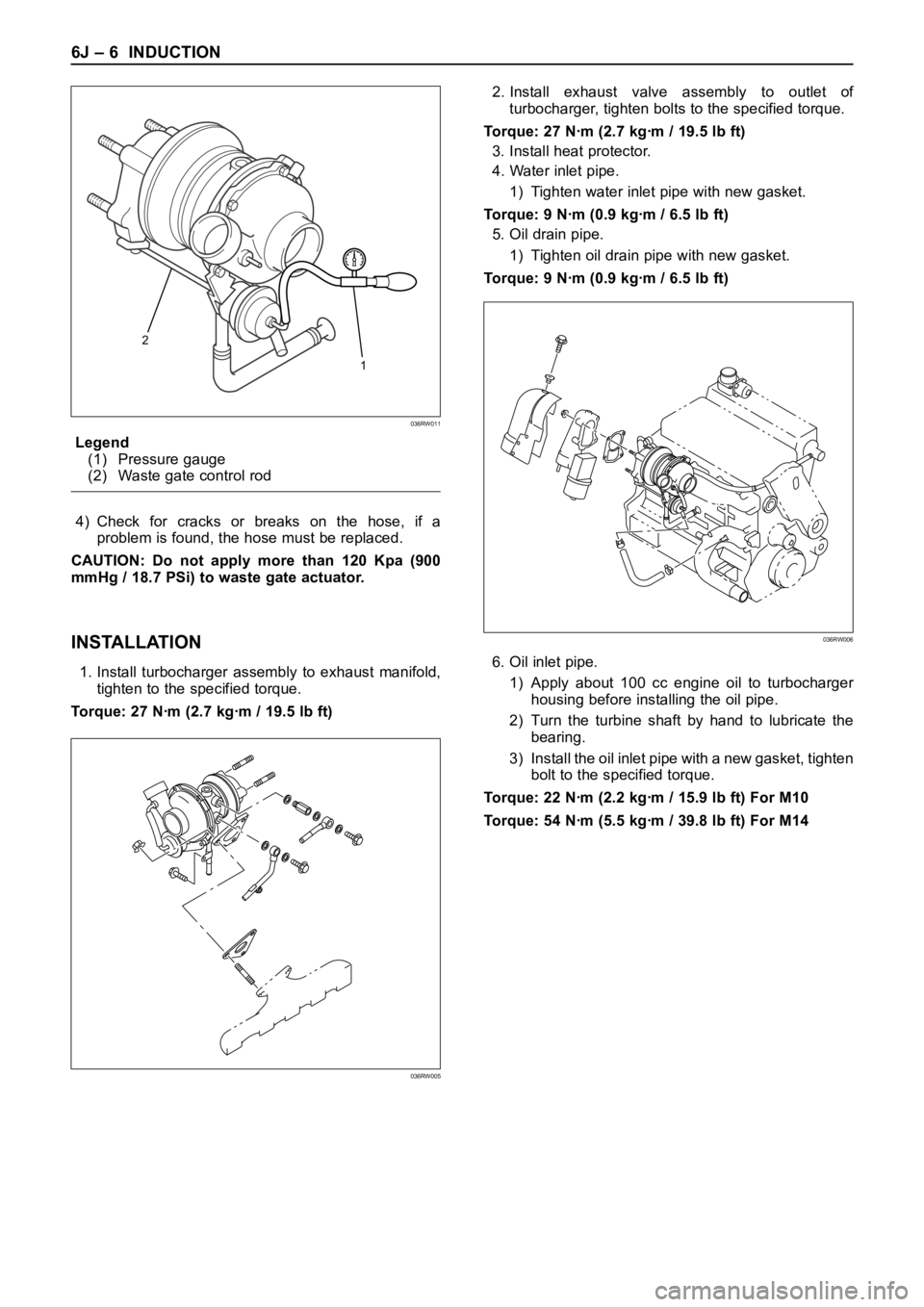
Legend
(1) Pressure gauge
(2) Waste gate control rod
4) Check for cracks or breaks on the hose, if a
problem is found, the hose must be replaced.
CAUTION: Do not apply more than 120 Kpa (900
mmHg / 18.7 PSi) to waste gate actuator.
INSTALLATION
1. Install turbocharger assembly to exhaust manifold,
tighten to the specified torque.
Torque: 27 Nꞏm (2.7 kgꞏm / 19.5 lb ft)2. Install exhaust valve assembly to outlet of
turbocharger, tighten bolts to the specified torque.
Torque: 27 Nꞏm (2.7 kgꞏm / 19.5 lb ft)
3. Install heat protector.
4. Water inlet pipe.
1) Tighten water inlet pipe with new gasket.
Torque: 9 Nꞏm (0.9 kgꞏm / 6.5 lb ft)
5. Oil drain pipe.
1) Tighten oil drain pipe with new gasket.
Torque: 9 Nꞏm (0.9 kgꞏm / 6.5 lb ft)
6. Oil inlet pipe.
1) Apply about 100 cc engine oil to turbocharger
housing before installing the oil pipe.
2) Turn the turbine shaft by hand to lubricate the
bearing.
3) Install the oil inlet pipe with a new gasket, tighten
bolt to the specified torque.
Torque: 22 Nꞏm (2.2 kgꞏm / 15.9 lb ft) For M10
Torque: 54 Nꞏm (5.5 kgꞏm / 39.8 lb ft) For M14
2
1
036RW011
036RW005
036RW006
Page 5684 of 6000
INDUCTION 6J – 7
7. Water inlet pipe.
1) Install water inlet pipe with a new gasket, tighten
bolts to the specified torque.
Torque: 9 Nꞏm (0.9 kgꞏm / 6.5 lb ft)
8. Install intercooler assembly.
Refer to “Intercooler” in this manual.
9. Install air cleaner cover with air duct.
10. Fill engine coolant to full level.
11. Install battery and connect battery cable.
036RW005
Page 5687 of 6000
6J – 10 INDUCTION
INTAKE MANIFOLD
REMOVAL
1. Drain engine coolant and remove water hose from
thermostat housing
2. Remove intercooler assembly.
3. Remove bracket fixing bolt of oil level gauge guide
tube.
4. Remove PCV hose.
5. Remove hoses from EGR valve, EGR vacuum
sensor and outlet of heater unit.
6. Disconnect harness connector from MAP sensor,
EGR vacuum sensor, ETC sensor, Water
temperature unit, IAT sensor and EVRV.
7. Remove high pressure oil pipe.
8. Remove two way check valve.
9. Remove fuel pipe.
10. Remove fixing bolts and nuts of intake manifold,
remove intake manifold assembly.
Legend
(1) Intake manifold
(2) Fixing portion of throttle valve
(3) EGR passage
(4) EGR valve
2
3
4
1
Legend
(1) Intake Manifold
(2) Throttle Valve Assembly
(3) EGR Valve
(4) Gasket
025RW022
3124
025RW031