Page 1742 of 6000

ENGINE MECHANICAL 6A – 9
SERVICING
Servicing refers to general maintenance procedures to
be performed by qualified service personnel.
MODEL IDENTIFICATION
Engine Serial Number
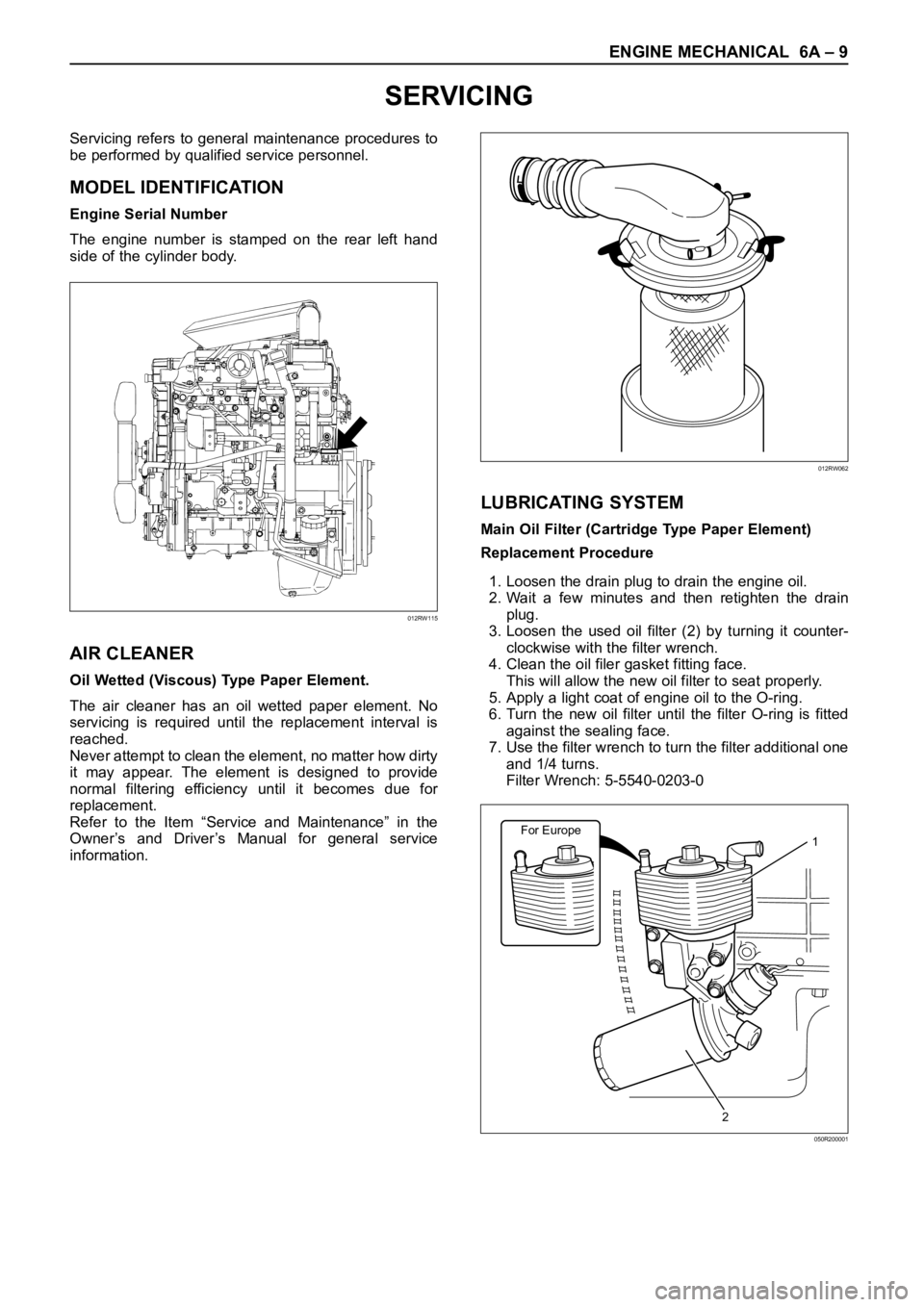
The engine number is stamped on the rear left hand
side of the cylinder body.
AIR CLEANER
Oil Wetted (Viscous) Type Paper Element.
The air cleaner has an oil wetted paper element. No
servicing is required until the replacement interval is
reached.
Never attempt to clean the element, no matter how dirty
it may appear. The element is designed to provide
normal filtering efficiency until it becomes due for
replacement.
Refer to the Item “Service and Maintenance” in the
Owner’s and Driver’s Manual for general service
information.
LUBRICATING SYSTEM
Main Oil Filter (Cartridge Type Paper Element)
Replacement Procedure
1. Loosen the drain plug to drain the engine oil.
2. Wait a few minutes and then retighten the drain
plug.
3. Loosen the used oil filter (2) by turning it counter-
clockwise with the filter wrench.
4. Clean the oil filer gasket fitting face.
This will allow the new oil filter to seat properly.
5. Apply a light coat of engine oil to the O-ring.
6. Turn the new oil filter until the filter O-ring is fitted
against the sealing face.
7. Use the filter wrench to turn the filter additional one
and 1/4 turns.
Filter Wrench: 5-5540-0203-0
012RW115
012RW062
For Europe1
2
050R200001
Page 1743 of 6000

6A – 10 ENGINE MECHANICAL
8. Check the engine oil level and replenish to the
specified level if required.
9. Start the engine and check for oil leakage from the
main oil filter.
FUEL SYSTEM
Fuel filter
Replacement Procedure
1. Loosen the used fuel filter by turning it
counterclockwise with the filter wrench.
Filter Wrench : 5-8840-0203-0
2. Clean the filter cover fitting faces.
This will allow the new fuel filter to seat properly.
3. Apply a light coat of engine oil to the O-ring.
4. Turn the fuel filter until the sealing face comes in
contact with the O-ring.
5. Turn the fuel filter with a filter wrench 2/3 of a turn
until sealed.
Filter Wrench: 5-8840-0203-0Legend
(1) Priming pump
6. Operate the priming pump until the air is discharged
completely from fuel system.
NOTE: The use of an Isuzu genuine fuel filter is
strongly recommended.
COOLING SYSTEM
Coolant Level
Check the coolant level and replenish the radiator
reserve tank as necessary.
If the coolant level falls below the “‘MIN” line, carefully
check the cooling system for leakage. Then add
enough coolant to bring the level up to the “MAX” line.
NOTE: Do not overfill the reserve tank.
012RW112
012RW078
1
012RW111
012RW080
Page 1747 of 6000
6A – 14 ENGINE MECHANICAL
TIGHTENING TORQUE
Timing Gear Case, Timing Gear
Nꞏm (kgꞏm/lbꞏft)
75(7.6/55)
Apply engine oil to
thread and seat 8(0.8/6)
20(2.0/14.5)
51(5.2/38)
25(2.5/18)
020RW00001
Page 1748 of 6000
ENGINE MECHANICAL 6A – 15
Cylinder Head, Flywheel, Crank Case, Oil Pan
Nꞏm (kgꞏm/lbꞏft)
012RW121
1st
49N•m(5.0kg•m/36 Ib ft)
167(17.0/123)
8(0.8/5.8)
20(2.0/14.5)
20(2.0/14.5)
30(3.1/22)
25(2.5/18)
2nd
60
1st
59N•m(6kg•m/43 Ib ft)
2nd
60-90
1st
29N•m(3.0kg•m/22 Ib ft)
2nd
45-60
3rd
60
19(1.9/14)
Page 1752 of 6000
ENGINE MECHANICAL 6A – 19
Injector
Nꞏm (kgꞏm/lbꞏft)
E06R200022
With
spacer type
Without
spacer type
20Nꞏm(2.0kgꞏm/14 Ib ft)
7Nꞏm(0.7kgꞏm/61 Ib in)
Recheck tightening torque
after tighten the oil rail
Apply engine oil on the
thread of stud bolts
20Nꞏm(2.0kgꞏm/14 Ib ft)
Tighten 30Nꞏm(3.1kgꞏm/22 Ib ft)
Then loosen it again tighten with
24Nꞏm(2.4kgꞏm/17 Ib ft)
Apply engine oil
both side
Page 1753 of 6000
6A – 20 ENGINE MECHANICAL
High Pressure Oil Pipe
Nꞏm (kgꞏm/lbꞏft)
80(8.1/57.9)
80(8.1/57.9)
80(8.1/57.9)
80(8.1/57.9)
052R200002
Page 1760 of 6000
ENGINE MECHANICAL 6A – 27
Illustration Tool No. Tool Name
SPECIAL TOOLS
5-8840-0266-0 Angle Gauge
5-8840-2360-0 Rear Oil Seal Remover
5-8840-2359-0 Rear Oil Seal Installer
5-8840-2061-0
Front Oil Seal Installer
901LX030
901LX040
901LX025
901LX039901RV061
9-8522-0021-0 Crankshaft Gear Installer
Page 1762 of 6000

ENGINE MECHANICAL 6A – 29
13 Vacuum Hose
1) Disconnect vacuum hose from vacuum pump.
14. Starter Harness
1) Disconnect B terminal and put cable harness
close to chassis side.
2) Disconnect S terminal connector.
15. Engine Harness
1) Disconnect engine harness close to engine side.
16. Fuel Pipe
1) Remove fuel pipe from fuel pump and take care
not to spill fuel and let dust enter.
17. Engine Ground Cable
1) Disconnect ground cable from left rear side of
timing gear case.
18. Vacuum Hose: Vacuum Tank
Disconnect vacuum hose from vacuum pump side.
19. Glow Plug Harness
20. Transmission Assembly
1) Set transmission support tool under the
transmission.
2) Remove transmission rear mount.
3) Remove transmission fixing bolt from rear of
engine assembly except two bolts.
4) Carefully hang up engine assembly with a hoist.
5) Remove remaining two transmission fixing bolts.
6) Remove transmission assembly.
7) Remove heater hose.
8) Disconnect wire harness connector for shift on
the fly.
9) Remove vacuum hose.
21. Prepare Engine Stand
22. Engine Assembly
1) Remove engine mount fixing bolts.
2) Carefully hang up the engine assembly.
3) Take out the engine assembly making sure not
to damage the brake oil pipe and other pipe etc.
INSTALLATION
1. Engine assembly
1) Install engine in mounting position by using
hoist.
2. Transmission Assembly
1) Refer to transmission installation steps in
section 7.
3. Engine Mounting
1) After all fixing bolts (left: two bolts, rights: two
bolts) were inserted in every hole, tighten fixing
bolts to the specified torque.
Torque: 40 Nꞏm (4 kgꞏm/29 lbꞏft)
4. Glow Plug Harness
5. Vacuum Hose
1) Connect Vacuum Hose to Vacuum Pump
6. Engine Ground Cable
7. Fuel Pipe
1) Install fuel pipe to fuel pump.
8. Engine Harness
9. Starter Harness
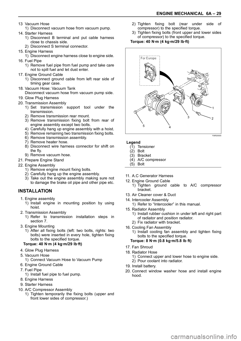
10. A/C Compressor Assembly
1) Tighten temporarily the fixing bolts (upper and
front lower sides of compressor.)2) Tighten fixing bolt (rear under side of
compressor) to the specified torque.
3) Tighten fixing bolts (front upper and lower sides
of compressor) to the specified torque.
To r q u e : 4 0 N ꞏm ( 4 k g ꞏm / 2 9 l b ꞏf t )
Legend
(1) Tensioner
(2) Bolt
(3) Bracket
(4) A/C compressor
(5) Bolt
11. A.C Generator Harness
12. Engine Ground Cable
1) Tighten ground cable to A/C compressor
bracket.
13. Air Cleaner cover & Duct
14. Intercooler Assembly
1) Refer to “Intercooler” in this manual.
15. Radiator Assembly
1) Install rubber cushion in under left and right part
of radiator and position radiator.
2) Fix radiator with bracket.
16. Cooling Fan Assembly
1) Install cooling fan assembly and tighten fixing
bolts to the specified torque.
Torque: 8 Nꞏm (0.8 kgꞏm/5.8 lb ft)
17. Fan Shroud
18. Radiator Hose
1) Connect upper and lower hose to engine side.
2) Pour coolant into radiator.
19. Install battery.
20. Connect window washer hose and install engine
hood.
1
2
3
4
5
For E urope
F06R200005