1998 OPEL FRONTERA torque
[x] Cancel search: torquePage 1110 of 6000
6D3–19 STARTING AND CHARGING SYSTEM
Generator
Removal
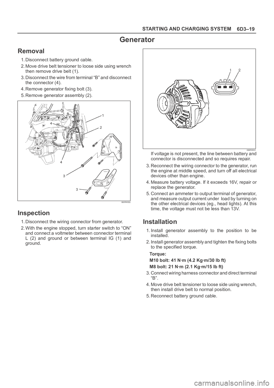
1. Disconnect battery ground cable.
2. Move drive belt tensioner to loose side using wrench
then remove drive belt (1).
3. Disconnect the wire from terminal “B” and disconnect
the connector (4).
4. Remove generator fixing bolt (3).
5. Remove generator assembly (2).
060RW002
Inspection
1. Disconnect the wiring connector from generator.
2. With the engine stopped, turn starter switch to “ON”
and connect a voltmeter between connector terminal
L (2) and ground or between terminal IG (1) and
ground.
066RW001If voltage is not present, the line between battery and
connector is disconnected and so requires repair.
3. Reconnect the wiring connector to the generator, run
the engine at middle speed, and turn off all electrical
devices other than engine.
4. Measure battery voltage. If it exceeds 16V, repair or
replace the generator.
5. Connect an ammeter to output terminal of generator,
and measure output current under load by turning on
the other electrical devices (eg., head lights). At this
time, the voltage must not be less than 13V.
Installation
1. Install generator assembly to the position to be
installed.
2. Install generator assembly and tighten the fixing bolts
to the specified torque.
To r q u e :
M10 bolt: 41 Nꞏm (4.2 Kgꞏm/30 lb ft)
M8 bolt: 21 Nꞏm (2.1 Kgꞏm/15 lb ft)
3. Connect wiring harness connector and direct terminal
“B”.
4. Move drive belt tensioner to loose side using wrench,
then install drive belt to normal position.
5. Reconnect battery ground cable.
Page 1116 of 6000
6D3–25 STARTING AND CHARGING SYSTEM
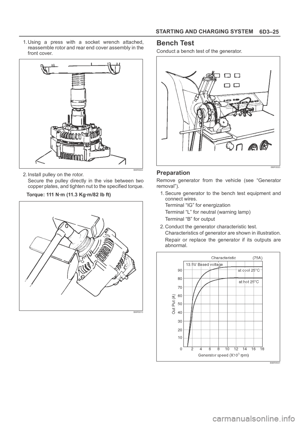
1. Using a press with a socket wrench attached,
reassemble rotor and rear end cover assembly in the
front cover.
066RS022
2. Install pulley on the rotor.
Secure the pulley directly in the vise between two
copper plates, and tighten nut to the specified torque.
Torque: 111 Nꞏm (11.3 Kgꞏm/82 lb ft)
066RS010
Bench Test
Conduct a bench test of the generator.
066RS023
Preparation
Remove generator from the vehicle (see “Generator
removal”).
1. Secure generator to the bench test equipment and
connect wires.
Terminal “IG” for energization
Terminal “L” for neutral (warning lamp)
Terminal “B” for output
2. Conduct the generator characteristic test.
Characteristics of generator are shown in illustration.
Repair or replace the generator if its outputs are
abnormal.
B06RW001
Page 1139 of 6000
6E–22
ENGINE DRIVEABILITY AND EMISSIONS
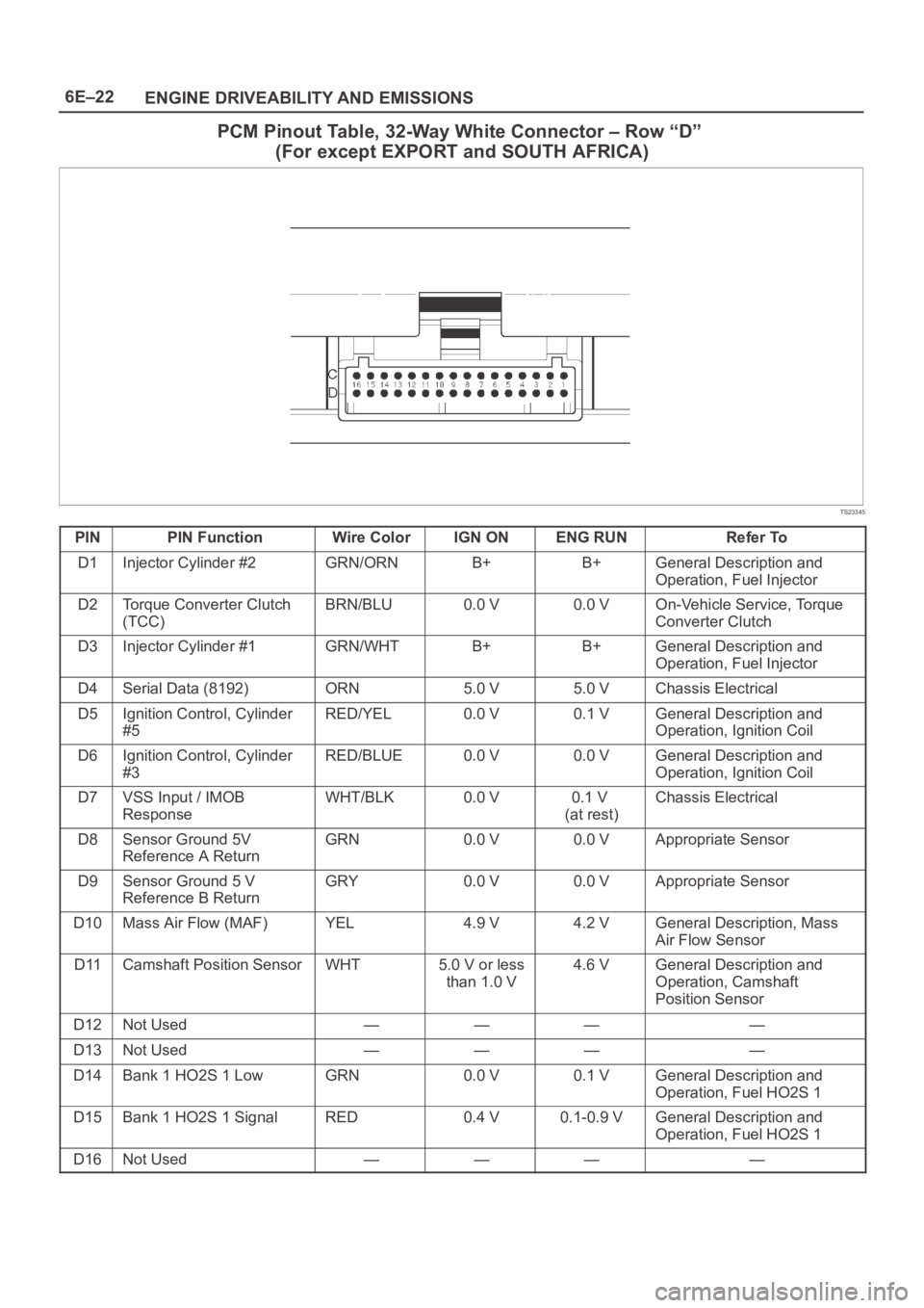
PCM Pinout Table, 32-Way White Connector – Row “D”
(For except EXPORT and SOUTH AFRICA)
TS23345
PINPIN FunctionWire ColorIGN ONENG RUNRefer To
D1Injector Cylinder #2GRN/ORNB+B+General Description and
Operation, Fuel Injector
D2Torque Converter Clutch
(TCC)BRN/BLU0.0 V0.0 VOn-Vehicle Service, Torque
Converter Clutch
D3Injector Cylinder #1GRN/WHTB+B+General Description and
Operation, Fuel Injector
D4Serial Data (8192)ORN5.0 V5.0 VChassis Electrical
D5Ignition Control, Cylinder
#5RED/YEL0.0 V0.1 VGeneral Description and
Operation, Ignition Coil
D6Ignition Control, Cylinder
#3RED/BLUE0.0 V0.0 VGeneral Description and
Operation, Ignition Coil
D7VSS Input / IMOB
ResponseWHT/BLK0.0 V0.1 V
(at rest)Chassis Electrical
D8Sensor Ground 5V
Reference A ReturnGRN0.0 V0.0 VAppropriate Sensor
D9Sensor Ground 5 V
Reference B ReturnGRY0.0 V0.0 VAppropriate Sensor
D10Mass Air Flow (MAF)YEL4.9 V4.2 VGeneral Description, Mass
Air Flow Sensor
D11Camshaft Position SensorWHT5.0 V or less
than 1.0 V4.6 VGeneral Description and
Operation, Camshaft
Position Sensor
D12Not Used————
D13Not Used————
D14Bank 1 HO2S 1 LowGRN0.0 V0.1 VGeneral Description and
Operation, Fuel HO2S 1
D15Bank 1 HO2S 1 SignalRED0.4 V0.1-0.9 VGeneral Description and
Operation, Fuel HO2S 1
D16Not Used————
Page 1140 of 6000
6E–23 ENGINE DRIVEABILITY AND EMISSIONS
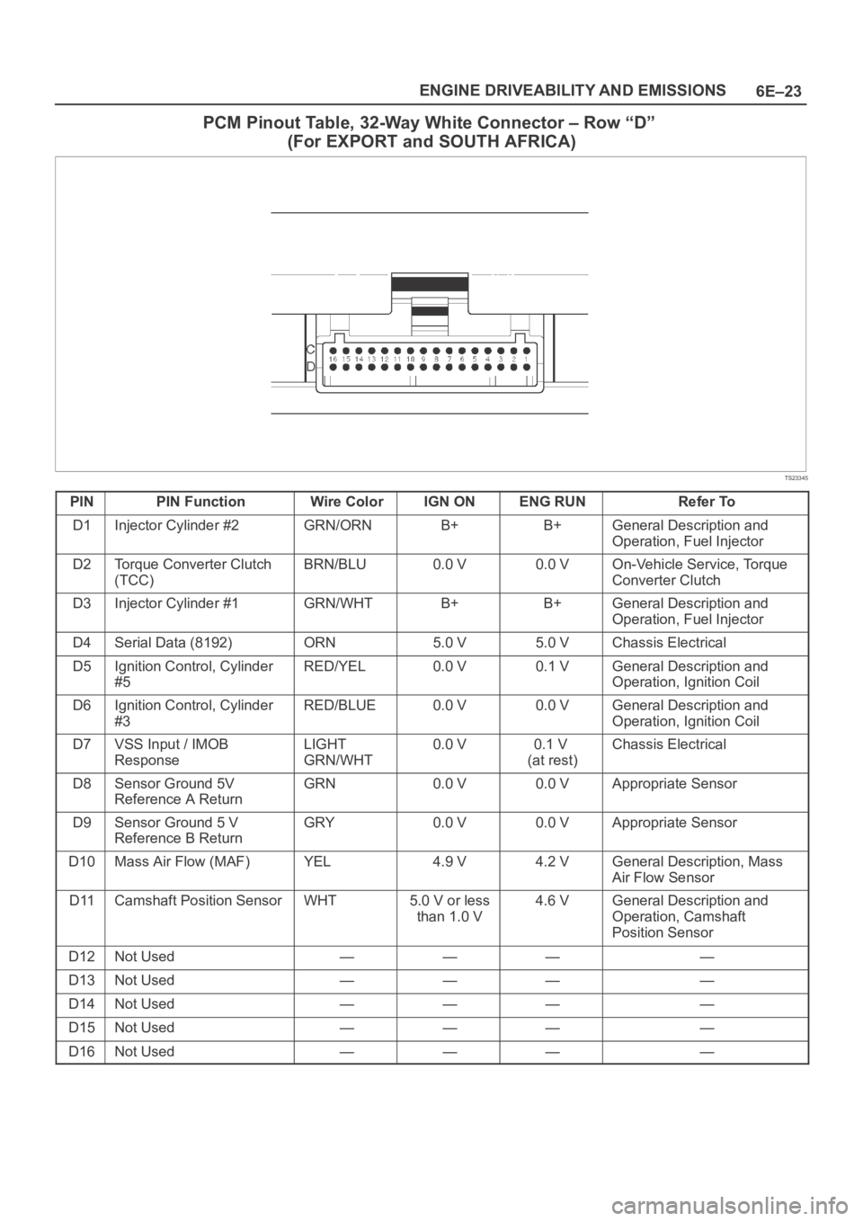
PCM Pinout Table, 32-Way White Connector – Row “D”
(For EXPORT and SOUTH AFRICA)
TS23345
PINPIN FunctionWire ColorIGN ONENG RUNRefer To
D1Injector Cylinder #2GRN/ORNB+B+General Description and
Operation, Fuel Injector
D2Torque Converter Clutch
(TCC)BRN/BLU0.0 V0.0 VOn-Vehicle Service, Torque
Converter Clutch
D3Injector Cylinder #1GRN/WHTB+B+General Description and
Operation, Fuel Injector
D4Serial Data (8192)ORN5.0 V5.0 VChassis Electrical
D5Ignition Control, Cylinder
#5RED/YEL0.0 V0.1 VGeneral Description and
Operation, Ignition Coil
D6Ignition Control, Cylinder
#3RED/BLUE0.0 V0.0 VGeneral Description and
Operation, Ignition Coil
D7VSS Input / IMOB
ResponseLIGHT
GRN/WHT0.0 V0.1 V
(at rest)Chassis Electrical
D8Sensor Ground 5V
Reference A ReturnGRN0.0 V0.0 VAppropriate Sensor
D9Sensor Ground 5 V
Reference B ReturnGRY0.0 V0.0 VAppropriate Sensor
D10Mass Air Flow (MAF)YEL4.9 V4.2 VGeneral Description, Mass
Air Flow Sensor
D11Camshaft Position SensorWHT5.0 V or less
than 1.0 V4.6 VGeneral Description and
Operation, Camshaft
Position Sensor
D12Not Used————
D13Not Used————
D14Not Used————
D15Not Used————
D16Not Used————
Page 1382 of 6000
6E–265 ENGINE DRIVEABILITY AND EMISSIONS
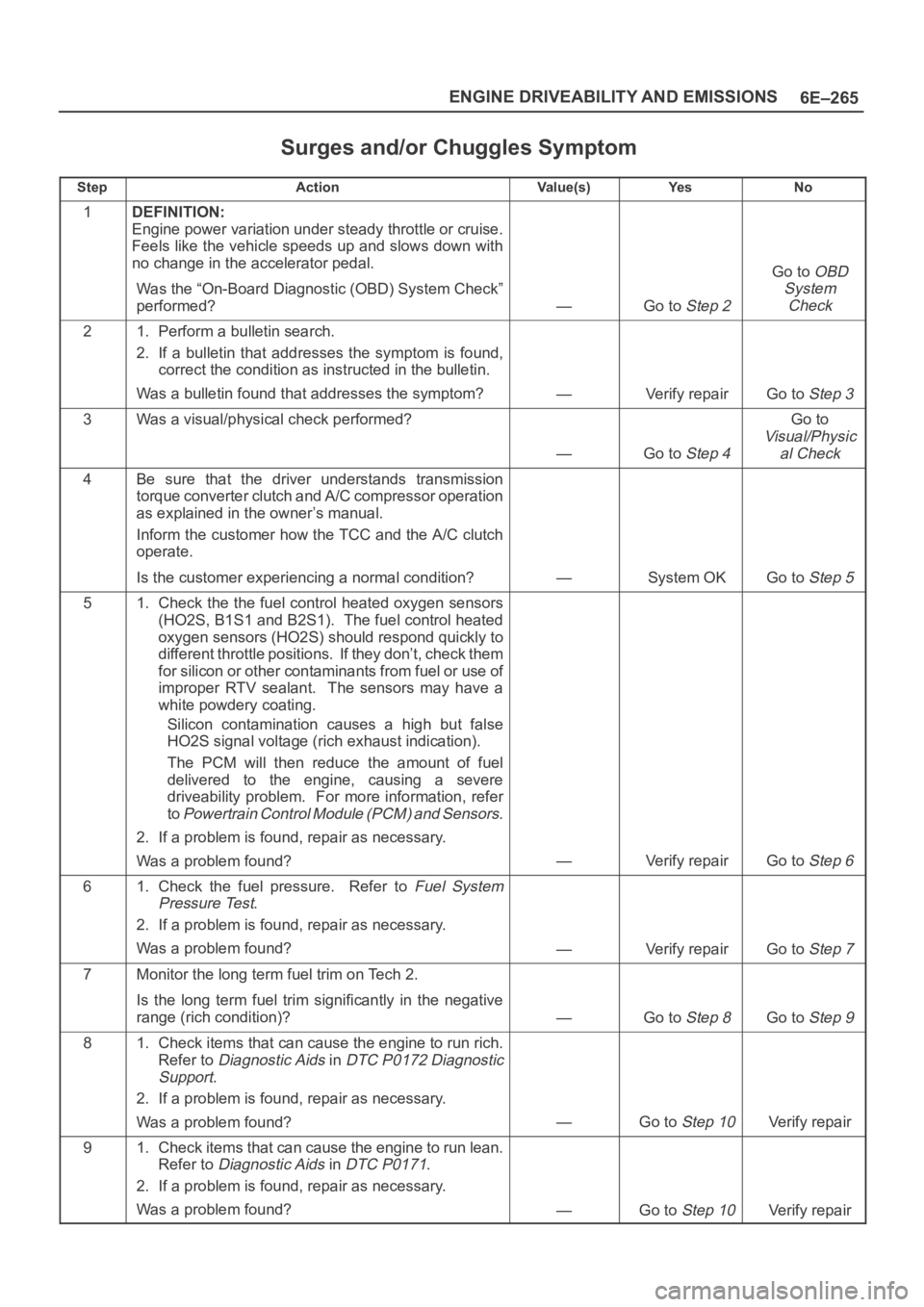
Surges and/or Chuggles Symptom
StepActionVa l u e ( s )Ye sNo
1DEFINITION:
Engine power variation under steady throttle or cruise.
Feels like the vehicle speeds up and slows down with
no change in the accelerator pedal.
Was the “On-Board Diagnostic (OBD) System Check”
performed?
—Go to Step 2
Go to OBD
System
Check
21. Perform a bulletin search.
2. If a bulletin that addresses the symptom is found,
correct the condition as instructed in the bulletin.
Was a bulletin found that addresses the symptom?
—Verify repairGo to Step 3
3Was a visual/physical check performed?
—Go to Step 4
Go to
Visual/Physic
al Check
4Be sure that the driver understands transmission
torque converter clutch and A/C compressor operation
as explained in the owner’s manual.
Inform the customer how the TCC and the A/C clutch
operate.
Is the customer experiencing a normal condition?
—System OKGo to Step 5
51. Check the the fuel control heated oxygen sensors
(HO2S, B1S1 and B2S1). The fuel control heated
oxygen sensors (HO2S) should respond quickly to
different throttle positions. If they don’t, check them
for silicon or other contaminants from fuel or use of
improper RTV sealant. The sensors may have a
white powdery coating.
Silicon contamination causes a high but false
HO2S signal voltage (rich exhaust indication).
The PCM will then reduce the amount of fuel
delivered to the engine, causing a severe
driveability problem. For more information, refer
to
Powertrain Control Module (PCM) and Sensors.
2. If a problem is found, repair as necessary.
Was a problem found?
—Verify repairGo to Step 6
61. Check the fuel pressure. Refer to Fuel System
Pressure Test
.
2. If a problem is found, repair as necessary.
Was a problem found?
—Verify repairGo to Step 7
7Monitor the long term fuel trim on Tech 2.
Is the long term fuel trim significantly in the negative
range (rich condition)?
—Go to Step 8Go to Step 9
81. Check items that can cause the engine to run rich.
Refer to
Diagnostic Aids in DTC P0172 Diagnostic
Support
.
2. If a problem is found, repair as necessary.
Was a problem found?
—Go to Step 10Verify repair
91. Check items that can cause the engine to run lean.
Refer to
Diagnostic Aids in DTC P0171.
2. If a problem is found, repair as necessary.
Was a problem found?
—Go to Step 10Verify repair
Page 1386 of 6000
6E–269 ENGINE DRIVEABILITY AND EMISSIONS
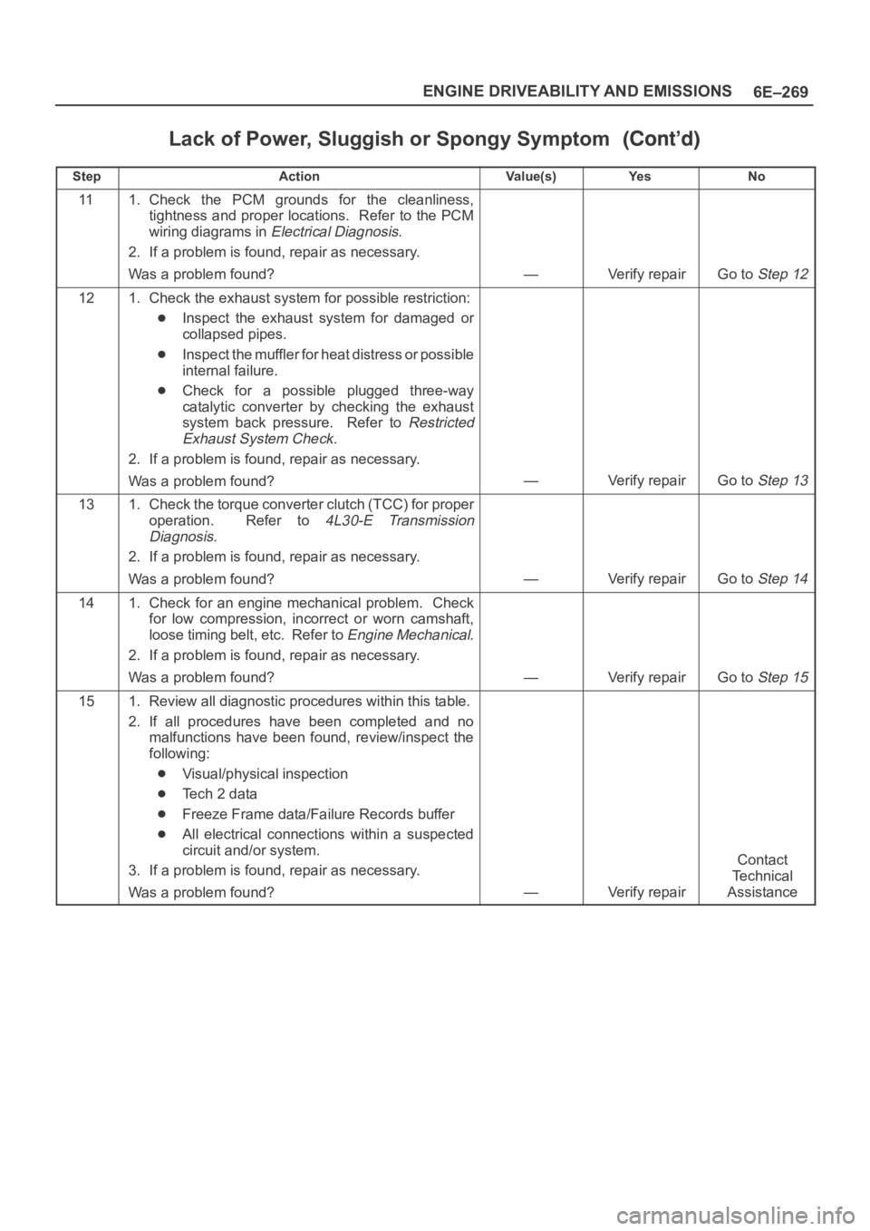
Lack of Power, Sluggish or Spongy Symptom
StepNo Ye s Va l u e ( s ) Action
111. Check the PCM grounds for the cleanliness,
tightness and proper locations. Refer to the PCM
wiring diagrams in
Electrical Diagnosis.
2. If a problem is found, repair as necessary.
Was a problem found?
—Verify repairGo to Step 12
121. Check the exhaust system for possible restriction:
Inspect the exhaust system for damaged or
collapsed pipes.
Inspect the muffler for heat distress or possible
internal failure.
Check for a possible plugged three-way
catalytic converter by checking the exhaust
system back pressure. Refer to
Restricted
Exhaust System Check
.
2. If a problem is found, repair as necessary.
Was a problem found?
—Verify repairGo to Step 13
131. Check the torque converter clutch (TCC) for proper
operation. Refer to
4L30-E Transmission
Diagnosis
.
2. If a problem is found, repair as necessary.
Was a problem found?
—Verify repairGo to Step 14
141. Check for an engine mechanical problem. Check
for low compression, incorrect or worn camshaft,
loose timing belt, etc. Refer to
Engine Mechanical.
2. If a problem is found, repair as necessary.
Was a problem found?
—Verify repairGo to Step 15
151. Review all diagnostic procedures within this table.
2. If all procedures have been completed and no
malfunctions have been found, review/inspect the
following:
Visual/physical inspection
Te c h 2 d a t a
Freeze Frame data/Failure Records buffer
All electrical connections within a suspected
circuit and/or system.
3. If a problem is found, repair as necessary.
Was a problem found?
—Verify repair
Contact
Te c h n i c a l
Assistance
Page 1465 of 6000
6E–348
ENGINE DRIVEABILITY AND EMISSIONS
oil to enter the cylinder, particularly if the deposits are
heavier on the side of the spark plug facing the intake
valve.
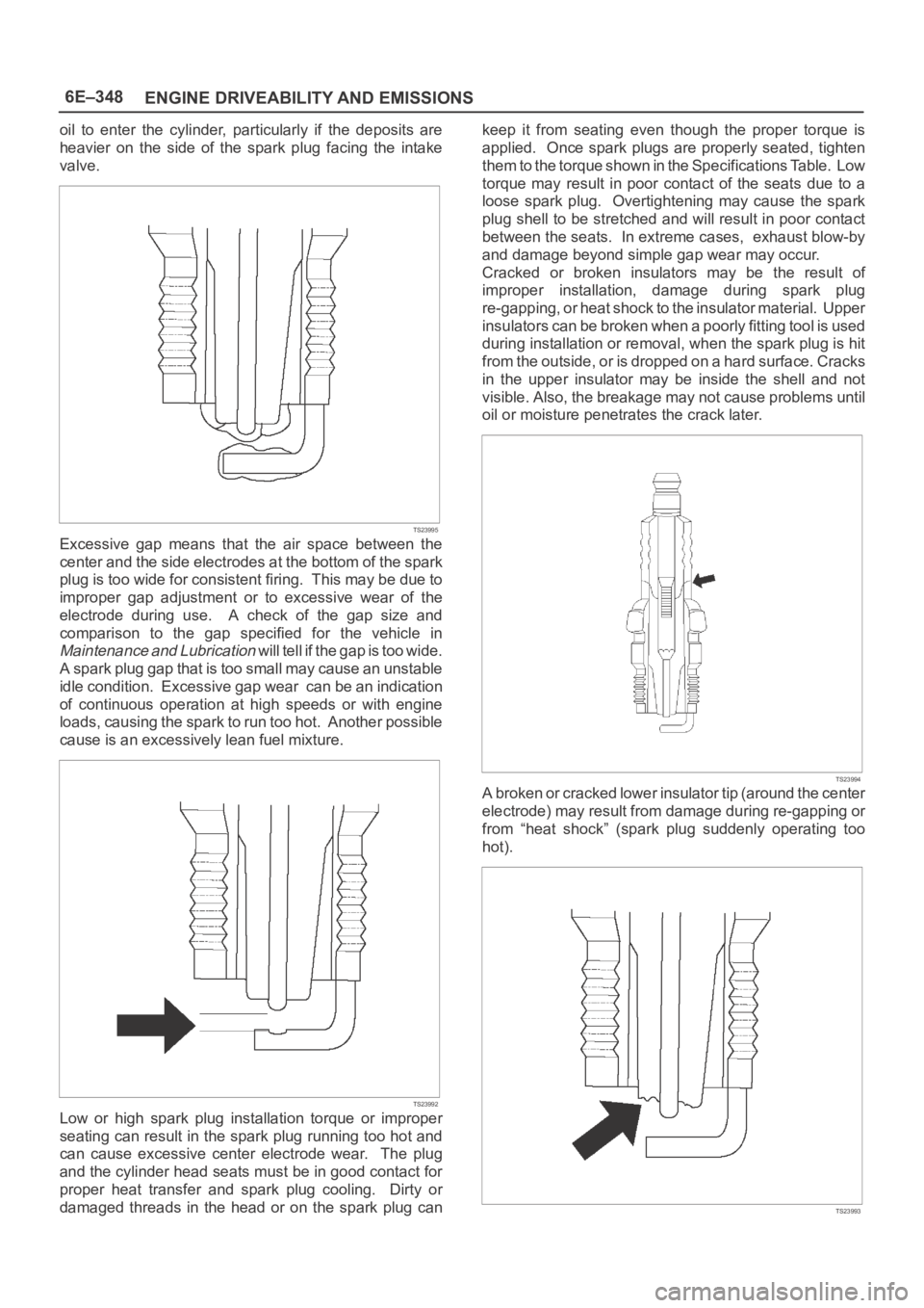
TS23995
Excessive gap means that the air space between the
center and the side electrodes at the bottom of the spark
plug is too wide for consistent firing. This may be due to
improper gap adjustment or to excessive wear of the
electrode during use. A check of the gap size and
comparison to the gap specified for the vehicle in
Maintenance and Lubrication will tell if the gap is too wide.
A spark plug gap that is too small may cause an unstable
idle condition. Excessive gap wear can be an indication
of continuous operation at high speeds or with engine
loads, causing the spark to run too hot. Another possible
cause is an excessively lean fuel mixture.
TS23992
Low or high spark plug installation torque or improper
seating can result in the spark plug running too hot and
can cause excessive center electrode wear. The plug
and the cylinder head seats must be in good contact for
proper heat transfer and spark plug cooling. Dirty or
damaged threads in the head or on the spark plug cankeep it from seating even though the proper torque is
applied. Once spark plugs are properly seated, tighten
them to the torque shown in the Specifications Table. Low
torque may result in poor contact of the seats due to a
loose spark plug. Overtightening may cause the spark
plug shell to be stretched and will result in poor contact
between the seats. In extreme cases, exhaust blow-by
and damage beyond simple gap wear may occur.
Cracked or broken insulators may be the result of
improper installation, damage during spark plug
re-gapping, or heat shock to the insulator material. Upper
insulators can be broken when a poorly fitting tool is used
during installation or removal, when the spark plug is hit
from the outside, or is dropped on a hard surface. Cracks
in the upper insulator may be inside the shell and not
visible. Also, the breakage may not cause problems until
oil or moisture penetrates the crack later.
TS23994
A broken or cracked lower insulator tip (around the center
electrode) may result from damage during re-gapping or
from “heat shock” (spark plug suddenly operating too
hot).
TS23993
Page 1472 of 6000
6F–1 ENGINE EXHAUST
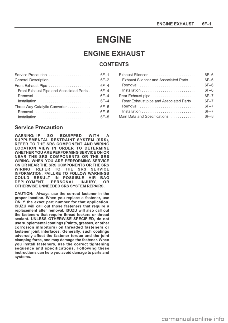
ENGINE
ENGINE EXHAUST
CONTENTS
Service Precaution 6F–1. . . . . . . . . . . . . . . . . . . . . .
General Description 6F–2. . . . . . . . . . . . . . . . . . . . .
Front Exhaust Pipe 6F–4. . . . . . . . . . . . . . . . . . . . . .
Front Exhaust Pipe and Associated Parts 6F–4.
Removal 6F–4. . . . . . . . . . . . . . . . . . . . . . . . . . . . .
Installation 6F–4. . . . . . . . . . . . . . . . . . . . . . . . . . . .
Three Way Catalytic Converter 6F–5. . . . . . . . . . . .
Removal 6F–5. . . . . . . . . . . . . . . . . . . . . . . . . . . . .
Installation 6F–5. . . . . . . . . . . . . . . . . . . . . . . . . . . . Exhaust Silencer 6F–6. . . . . . . . . . . . . . . . . . . . . . . .
Exhaust Silencer and Associated Parts 6F–6. . .
Removal 6F–6. . . . . . . . . . . . . . . . . . . . . . . . . . . . .
Installation 6F–6. . . . . . . . . . . . . . . . . . . . . . . . . . . .
Rear Exhaust pipe 6F–7. . . . . . . . . . . . . . . . . . . . . . .
Rear Exhaust pipe and Associated Parts 6F–7.
Removal 6F–7. . . . . . . . . . . . . . . . . . . . . . . . . . . . .
Installation 6F–7. . . . . . . . . . . . . . . . . . . . . . . . . . . .
Main Data and Specifications 6F–8. . . . . . . . . . . . .
Service Precaution
WARNING: IF SO EQUIPPED WITH A
SUPPLEMENTAL RESTRAINT SYSTEM (SRS),
REFER TO THE SRS COMPONENT AND WIRING
LOCATION VIEW IN ORDER TO DETERMINE
WHETHER YOU ARE PERFORMING SERVICE ON OR
NEAR THE SRS COMPONENTS OR THE SRS
WIRING. WHEN YOU ARE PERFORMING SERVICE
ON OR NEAR THE SRS COMPONENTS OR THE SRS
WIRING, REFER TO THE SRS SERVICE
INFORMATION. FAILURE TO FOLLOW WARNINGS
COULD RESULT IN POSSIBLE AIR BAG
DEPLOYMENT, PERSONAL INJURY, OR
OTHERWISE UNNEEDED SRS SYSTEM REPAIRS.
CAUTION: Always use the correct fastener in the
proper location. When you replace a fastener, use
ONLY the exact part number for that application.
ISUZU will call out those fasteners that require a
replacement after removal. ISUZU will also call out
the fasteners that require thread lockers or thread
sealant. UNLESS OTHERWISE SPECIFIED, do not
use supplemental coatings (Paints, greases, or other
corrosion inhibitors) on threaded fasteners or
fastener joint interfaces. Generally, such coatings
adversely affect the fastener torque and the joint
clamping force, and may damage the fastener. When
you install fasteners, use the correct tightening
sequence and specifications. Following these
instructions can help you avoid damage to parts and
systems.