Page 2311 of 6000
7A1–66
TRANSMISSION CONTROL SYSTEM (4L30–E)
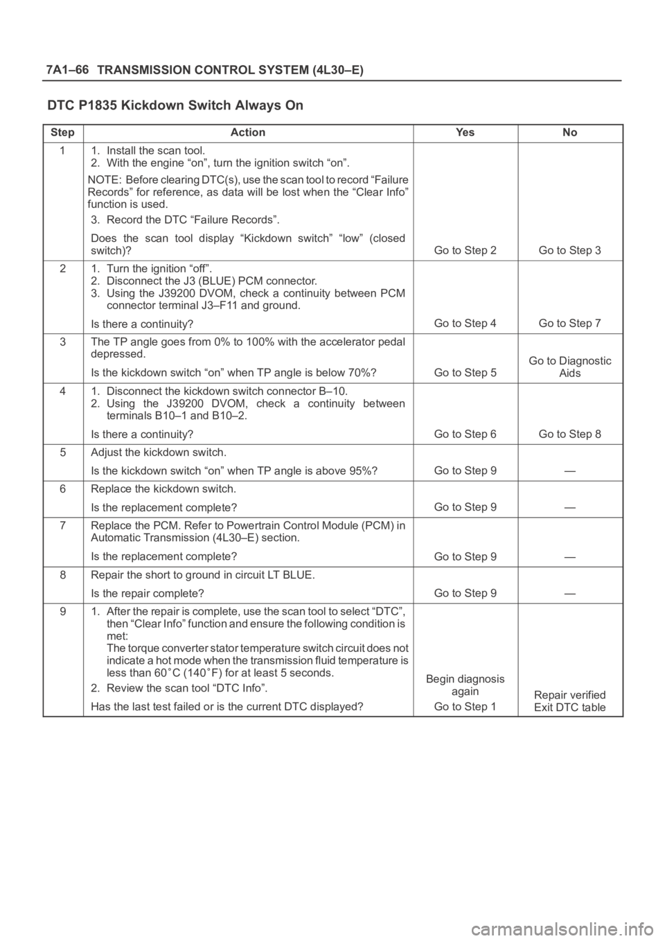
DTC P1835 Kickdown Switch Always On
StepActionYe sNo
11. Install the scan tool.
2. With the engine “on”, turn the ignition switch “on”.
NOTE: Before clearing DTC(s), use the scan tool to record “Failure
Records” for reference, as data will be lost when the “Clear Info”
function is used.
3. Record the DTC “Failure Records”.
Does the scan tool display “Kickdown switch” “low” (closed
switch)?
Go to Step 2Go to Step 3
21. Turn the ignition “off”.
2. Disconnect the J3 (BLUE) PCM connector.
3. Using the J39200 DVOM, check a continuity between PCM
connector terminal J3–F11 and ground.
Is there a continuity?
Go to Step 4Go to Step 7
3The TP angle goes from 0% to 100% with the accelerator pedal
depressed.
Is the kickdown switch “on” when TP angle is below 70%?
Go to Step 5
Go to Diagnostic
Aids
41. Disconnect the kickdown switch connector B–10.
2. Using the J39200 DVOM, check a continuity between
terminals B10–1 and B10–2.
Is there a continuity?
Go to Step 6Go to Step 8
5Adjust the kickdown switch.
Is the kickdown switch “on” when TP angle is above 95%?
Go to Step 9—
6Replace the kickdown switch.
Is the replacement complete?
Go to Step 9—
7Replace the PCM. Refer to Powertrain Control Module (PCM) in
Automatic Transmission (4L30–E) section.
Is the replacement complete?
Go to Step 9—
8Repair the short to ground in circuit LT BLUE.
Is the repair complete?
Go to Step 9—
91. After the repair is complete, use the scan tool to select “DTC”,
then “Clear Info” function and ensure the following condition is
met:
The torque converter stator temperature switch circuit does not
indicate a hot mode when the transmission fluid temperature is
less than 60
C (140F) for at least 5 seconds.
2. Review the scan tool “DTC Info”.
Has the last test failed or is the current DTC displayed?Begin diagnosis
again
Go to Step 1
Repair verified
Exit DTC table
Page 2315 of 6000
7A1–70
TRANSMISSION CONTROL SYSTEM (4L30–E)
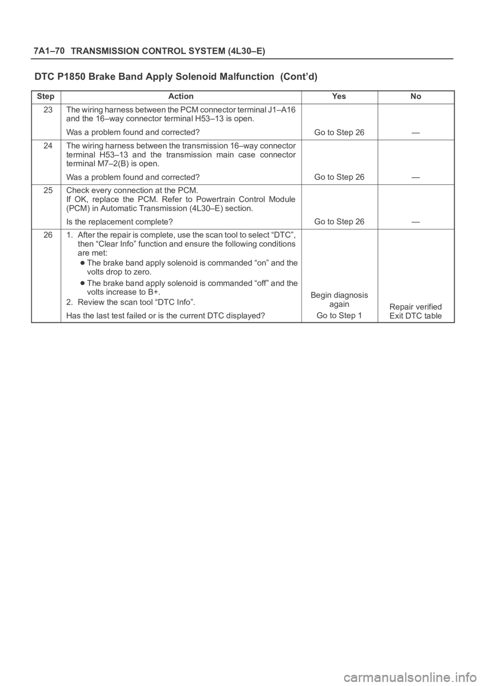
DTC P1850 Brake Band Apply Solenoid Malfunction (Cont’d)
StepNo Ye s Action
23The wiring harness between the PCM connector terminal J1–A16
and the 16–way connector terminal H53–13 is open.
Was a problem found and corrected?
Go to Step 26—
24The wiring harness between the transmission 16–way connector
terminal H53–13 and the transmission main case connector
terminal M7–2(B) is open.
Was a problem found and corrected?
Go to Step 26—
25Check every connection at the PCM.
If OK, replace the PCM. Refer to Powertrain Control Module
(PCM) in Automatic Transmission (4L30–E) section.
Is the replacement complete?
Go to Step 26—
261. After the repair is complete, use the scan tool to select “DTC”,
then “Clear Info” function and ensure the following conditions
are met:
The brake band apply solenoid is commanded “on” and the
volts drop to zero.
The brake band apply solenoid is commanded “off” and the
volts increase to B+.
2. Review the scan tool “DTC Info”.
Has the last test failed or is the current DTC displayed?
Begin diagnosis
again
Go to Step 1
Repair verified
Exit DTC table
Page 2318 of 6000
TRANSMISSION CONTROL SYSTEM (4L30–E)7A1–73
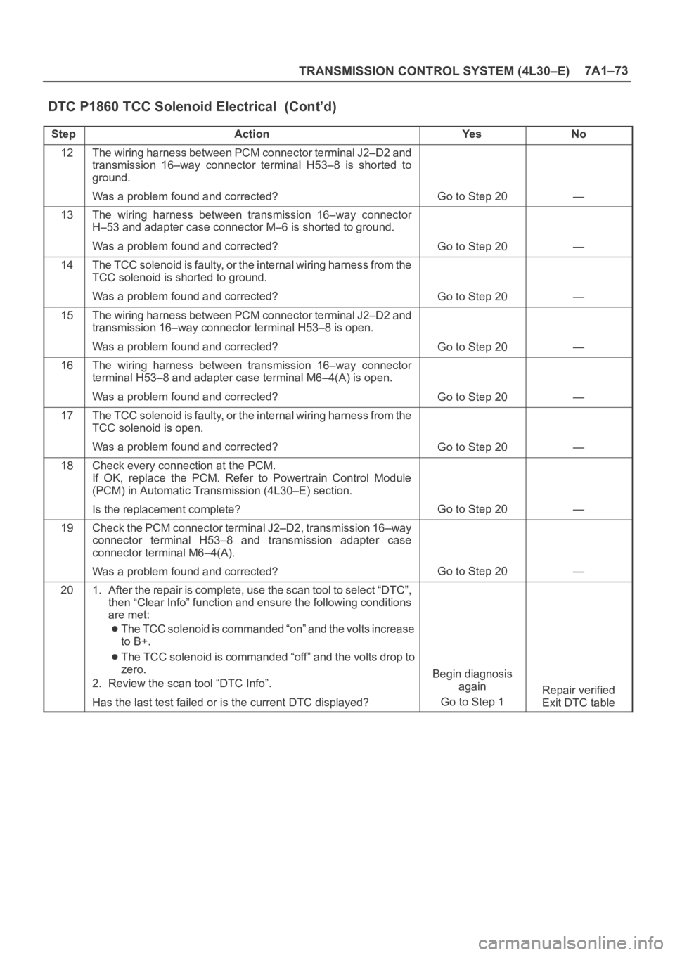
DTC P1860 TCC Solenoid Electrical (Cont’d)
StepNo Ye s Action
12The wiring harness between PCM connector terminal J2–D2 and
transmission 16–way connector terminal H53–8 is shorted to
ground.
Was a problem found and corrected?
Go to Step 20—
13The wiring harness between transmission 16–way connector
H–53 and adapter case connector M–6 is shorted to ground.
Was a problem found and corrected?
Go to Step 20—
14The TCC solenoid is faulty, or the internal wiring harness from t h e
TCC solenoid is shorted to ground.
Was a problem found and corrected?
Go to Step 20—
15The wiring harness between PCM connector terminal J2–D2 and
transmission 16–way connector terminal H53–8 is open.
Was a problem found and corrected?
Go to Step 20—
16The wiring harness between transmission 16–way connector
terminal H53–8 and adapter case terminal M6–4(A) is open.
Was a problem found and corrected?
Go to Step 20—
17The TCC solenoid is faulty, or the internal wiring harness from t h e
TCC solenoid is open.
Was a problem found and corrected?
Go to Step 20—
18Check every connection at the PCM.
If OK, replace the PCM. Refer to Powertrain Control Module
(PCM) in Automatic Transmission (4L30–E) section.
Is the replacement complete?
Go to Step 20—
19Check the PCM connector terminal J2–D2, transmission 16–way
connector terminal H53–8 and transmission adapter case
connector terminal M6–4(A).
Was a problem found and corrected?
Go to Step 20—
201. After the repair is complete, use the scan tool to select “DTC”,
then “Clear Info” function and ensure the following conditions
are met:
The TCC solenoid is commanded “on” and the volts increase
to B+.
The TCC solenoid is commanded “off” and the volts drop to
zero.
2. Review the scan tool “DTC Info”.
Has the last test failed or is the current DTC displayed?
Begin diagnosis
again
Go to Step 1
Repair verified
Exit DTC table
Page 3248 of 6000
8F–53 BODY STRUCTURE
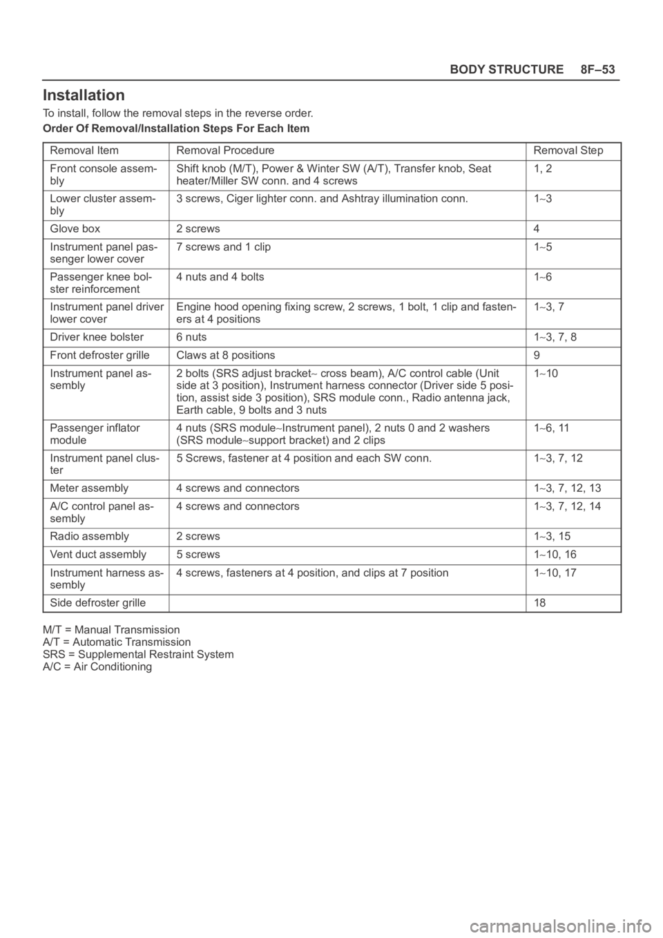
Installation
To install, follow the removal steps in the reverse order.
Order Of Removal/Installation Steps For Each Item
Removal Item
Removal ProcedureRemoval Step
Front console assem-
blyShift knob (M/T), Power & Winter SW (A/T), Transfer knob, Seat
heater/Miller SW conn. and 4 screws1, 2
Lower cluster assem-
bly3 screws, Ciger lighter conn. and Ashtray illumination conn.13
Glove box2 screws4
Instrument panel pas-
senger lower cover7 screws and 1 clip15
Passenger knee bol-
ster reinforcement4 nuts and 4 bolts16
Instrument panel driver
lower coverEngine hood opening fixing screw, 2 screws, 1 bolt, 1 clip and fasten-
ers at 4 positions13, 7
Driver knee bolster6 nuts13, 7, 8
Front defroster grilleClaws at 8 positions9
Instrument panel as-
sembly2 bolts (SRS adjust bracket cross beam), A/C control cable (Unit
side at 3 position), Instrument harness connector (Driver side 5 posi-
tion, assist side 3 position), SRS module conn., Radio antenna jack,
Earth cable, 9 bolts and 3 nuts110
Passenger inflator
module4 nuts (SRS moduleInstrument panel), 2 nuts 0 and 2 washers
(SRS module
support bracket) and 2 clips
16, 11
Instrument panel clus-
ter5 Screws, fastener at 4 position and each SW conn.13, 7, 12
Meter assembly4 screws and connectors13, 7, 12, 13
A/C control panel as-
sembly4 screws and connectors13, 7, 12, 14
Radio assembly2 screws13, 15
Vent duct assembly5 screws110, 16
Instrument harness as-
sembly4 screws, fasteners at 4 position, and clips at 7 position110, 17
Side defroster grille18
M/T = Manual Transmission
A/T = Automatic Transmission
SRS = Supplemental Restraint System
A/C = Air Conditioning
Page 3559 of 6000
10A–8
CRUISE CONTROL SYSTEM
Removal
1. Disconnect the battery ground cable.
2. Remove the cruise actuator Assembly (4).
Disconnect the connector (3).
R e m o v e t h e c a b l e e n d ( 1 ) f r o m t h e c a m l i n k ( c r u i s e
control side).
Loosen two fixing nuts (2).
Remove three actuator fixing screws.
825RW049
Installation
To install, follow the removal steps in the reverse order,
noting the following point.
1. Take care not to bend the cable excessively.
Mode Switch
Removal and Installation
Refer to the Mode Switch removal and installation steps
in Automatic Transmission section.
Page 3568 of 6000
PAGE BACK PAGE NEXT
THIS MALUAL INCLUDES THE FOLLOWING SECTIONS:
SECTION No. CONTRNTS
7A AUTOMATIC TRANSMISSION (4L30-E)
7A AUTOMATIC TRANSMISSION (AW30-40LE)
7A1 TRANSMISSION CONTROL SYSTEM (4L30-E)
7B MANUAL TRANSMISSION (AR-5)
7B MANUAL TRANSMISSION (MUA)
7C CLUTCH
HOME
7A
7A
7A1
7B
7B
7C
Page 4543 of 6000
6A–47
ENGINE MECHANICAL
Rear Oil Seal
Removal
1. Remove transmission assembly.
Refer to removal procedure for Transmission
section in this manual.
2. Remove flywheel.
3. Remove rear oil seal using a seal remover.
NOTE: Take care not to damage the crankshaft or oil seal
retainer when removing oil seal.
Installation
1. Apply engine oil to oil seal lip and install oil seal using
5–8840–2286–0.
015RS017
2. Install flywheel.
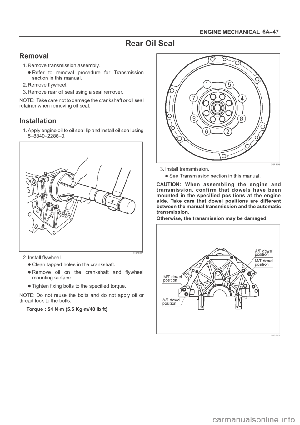
Clean tapped holes in the crankshaft.
Remove oil on the crankshaft and flywheel
mounting surface.
Tighten fixing bolts to the specified torque.
NOTE: Do not reuse the bolts and do not apply oil or
thread lock to the bolts.
Torque : 54 Nꞏm (5.5 Kgꞏm/40 lb ft)
015RS018
3. Install transmission.
See Transmission section in this manual.
CAUTION: W h e n a s s e m b l i n g t h e e n g i n e a n d
transmission, confirm that dowels have been
mounted in the specified positions at the engine
side. Take care that dowel positions are different
between the manual transmission and the automatic
transmission.
Otherwise, the transmission may be damaged.
012RS009
Page 4544 of 6000
6A–48
ENGINE MECHANICAL
Engine Assembly
Removal
035RW027
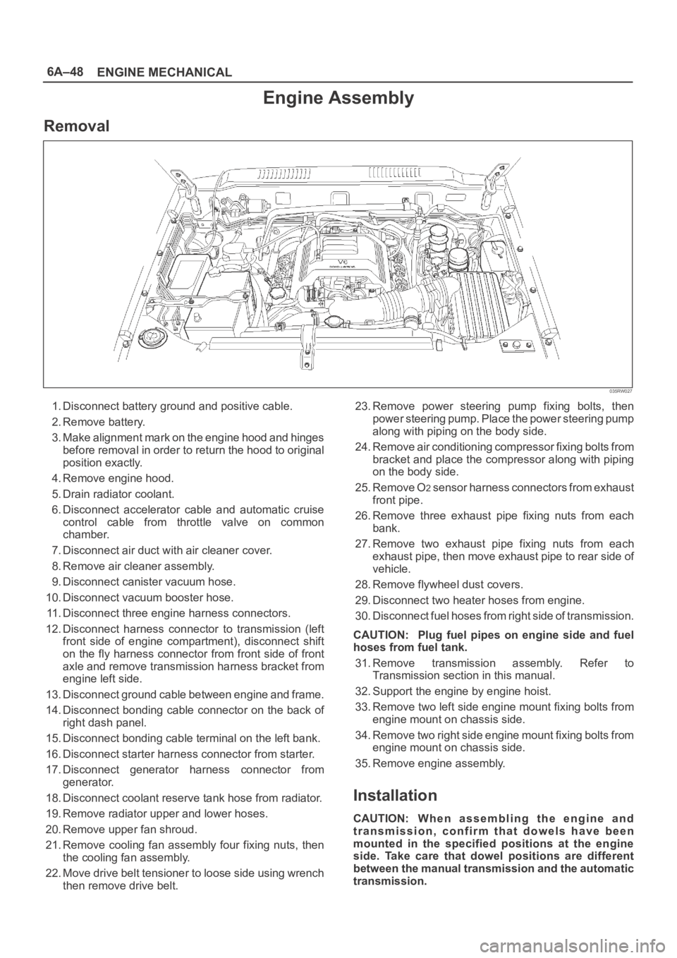
1. Disconnect battery ground and positive cable.
2. Remove battery.
3. Make alignment mark on the engine hood and hinges
before removal in order to return the hood to original
position exactly.
4. Remove engine hood.
5. Drain radiator coolant.
6. Disconnect accelerator cable and automatic cruise
control cable from throttle valve on common
chamber.
7. Disconnect air duct with air cleaner cover.
8. Remove air cleaner assembly.
9. Disconnect canister vacuum hose.
10. Disconnect vacuum booster hose.
11. Disconnect three engine harness connectors.
12. Disconnect harness connector to transmission (left
front side of engine compartment), disconnect shift
on the fly harness connector from front side of front
axle and remove transmission harness bracket from
engine left side.
13. Disconnect ground cable between engine and frame.
14. Disconnect bonding cable connector on the back of
right dash panel.
15. Disconnect bonding cable terminal on the left bank.
16. Disconnect starter harness connector from starter.
17. Disconnect generator harness connector from
generator.
18. Disconnect coolant reserve tank hose from radiator.
19. Remove radiator upper and lower hoses.
20. Remove upper fan shroud.
21. Remove cooling fan assembly four fixing nuts, then
the cooling fan assembly.
22. Move drive belt tensioner to loose side using wrench
then remove drive belt.23. Remove power steering pump fixing bolts, then
power steering pump. Place the power steering pump
along with piping on the body side.
24. Remove air conditioning compressor fixing bolts from
bracket and place the compressor along with piping
on the body side.
25. Remove O
2 sensor harness connectors from exhaust
front pipe.
26. Remove three exhaust pipe fixing nuts from each
bank.
27. Remove two exhaust pipe fixing nuts from each
exhaust pipe, then move exhaust pipe to rear side of
vehicle.
28. Remove flywheel dust covers.
29. Disconnect two heater hoses from engine.
30. Disconnect fuel hoses from right side of transmission.
CAUTION: Plug fuel pipes on engine side and fuel
hoses from fuel tank.
31. Remove transmission assembly. Refer to
Transmission section in this manual.
32. Support the engine by engine hoist.
33. Remove two left side engine mount fixing bolts from
engine mount on chassis side.
34. Remove two right side engine mount fixing bolts from
engine mount on chassis side.
35. Remove engine assembly.
Installation
CAUTION: W h e n a s s e m b l i n g t h e e n g i n e a n d
transmission, confirm that dowels have been
mounted in the specified positions at the engine
side. Take care that dowel positions are different
between the manual transmission and the automatic
transmission.