1998 OPEL FRONTERA tire size
[x] Cancel search: tire sizePage 4199 of 6000

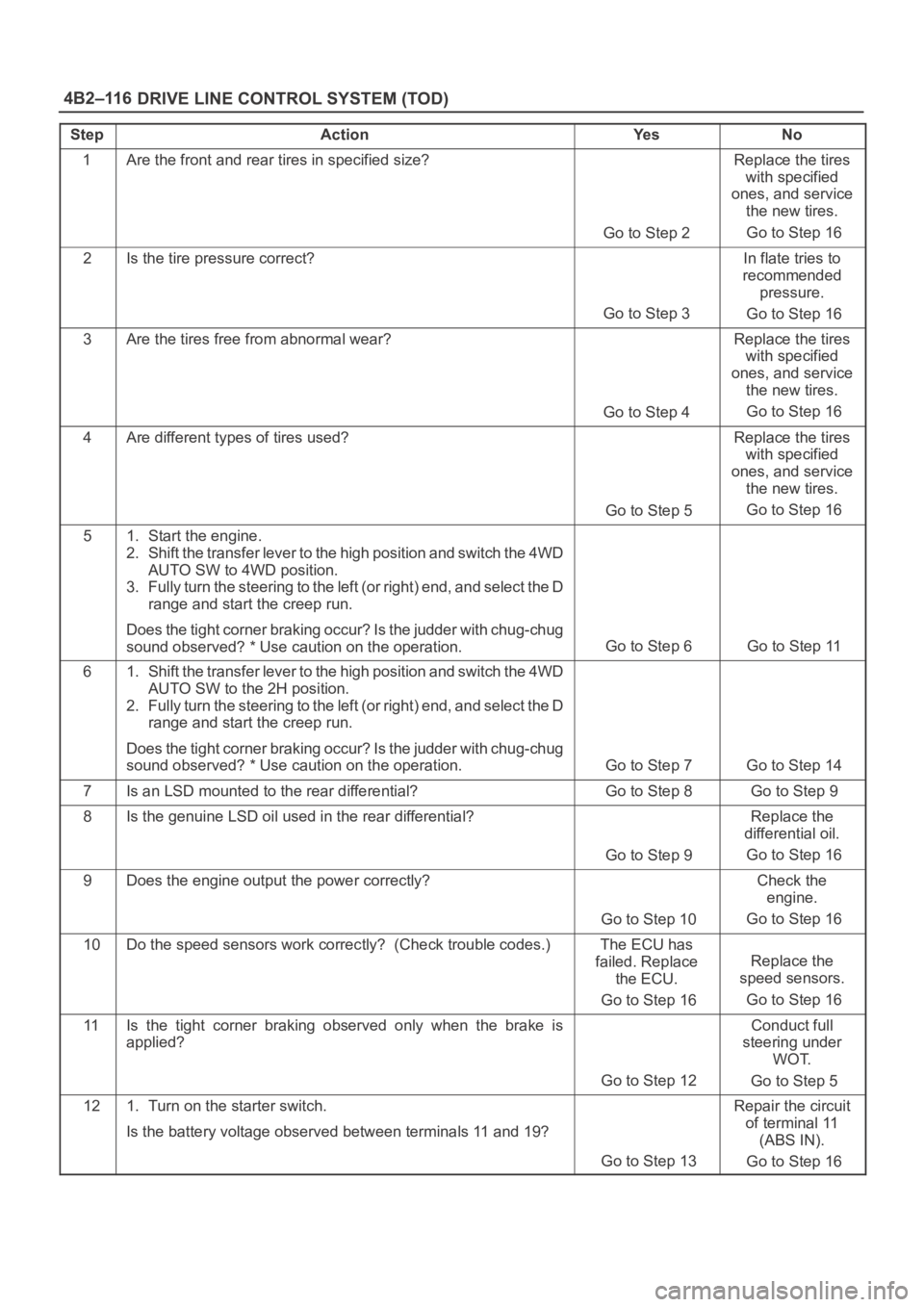
DRIVE LINE CONTROL SYSTEM (TOD) 4B2–116
StepActionYe sNo
1Are the front and rear tires in specified size?
Go to Step 2
Replace the tires
with specified
ones, and service
the new tires.
Go to Step 16
2Is the tire pressure correct?
Go to Step 3
In flate tries to
recommended
pressure.
Go to Step 16
3Are the tires free from abnormal wear?
Go to Step 4
Replace the tires
with specified
ones, and service
the new tires.
Go to Step 16
4Are different types of tires used?
Go to Step 5
Replace the tires
with specified
ones, and service
the new tires.
Go to Step 16
51. Start the engine.
2. Shift the transfer lever to the high position and switch the 4WD
AUTO SW to 4WD position.
3. Fully turn the steering to the left (or right) end, and select the D
range and start the creep run.
Does the tight corner braking occur? Is the judder with chug-chug
sound observed? * Use caution on the operation.
Go to Step 6 Go to Step 11
61. Shift the transfer lever to the high position and switch the 4WD
AUTO SW to the 2H position.
2. Fully turn the steering to the left (or right) end, and select the D
range and start the creep run.
Does the tight corner braking occur? Is the judder with chug-chug
sound observed? * Use caution on the operation.
Go to Step 7 Go to Step 14
7Is an LSD mounted to the rear differential? Go to Step 8 Go to Step 9
8Is the genuine LSD oil used in the rear differential?
Go to Step 9
Replace the
differential oil.
Go to Step 16
9Does the engine output the power correctly?
Go to Step 10
Check the
engine.
Go to Step 16
10Do the speed sensors work correctly? (Check trouble codes.)The ECU has
failed. Replace
the ECU.
Go to Step 16
Replace the
speed sensors.
Go to Step 16
11Is the tight corner braking observed only when the brake is
applied?
Go to Step 12
Conduct full
steering under
WOT.
Go to Step 5
121. Turn on the starter switch.
Is the battery voltage observed between terminals 11 and 19?
Go to Step 13
Repair the circuit
of terminal 11
(ABS IN).
Go to Step 16
Page 4507 of 6000

6A–11
ENGINE MECHANICAL
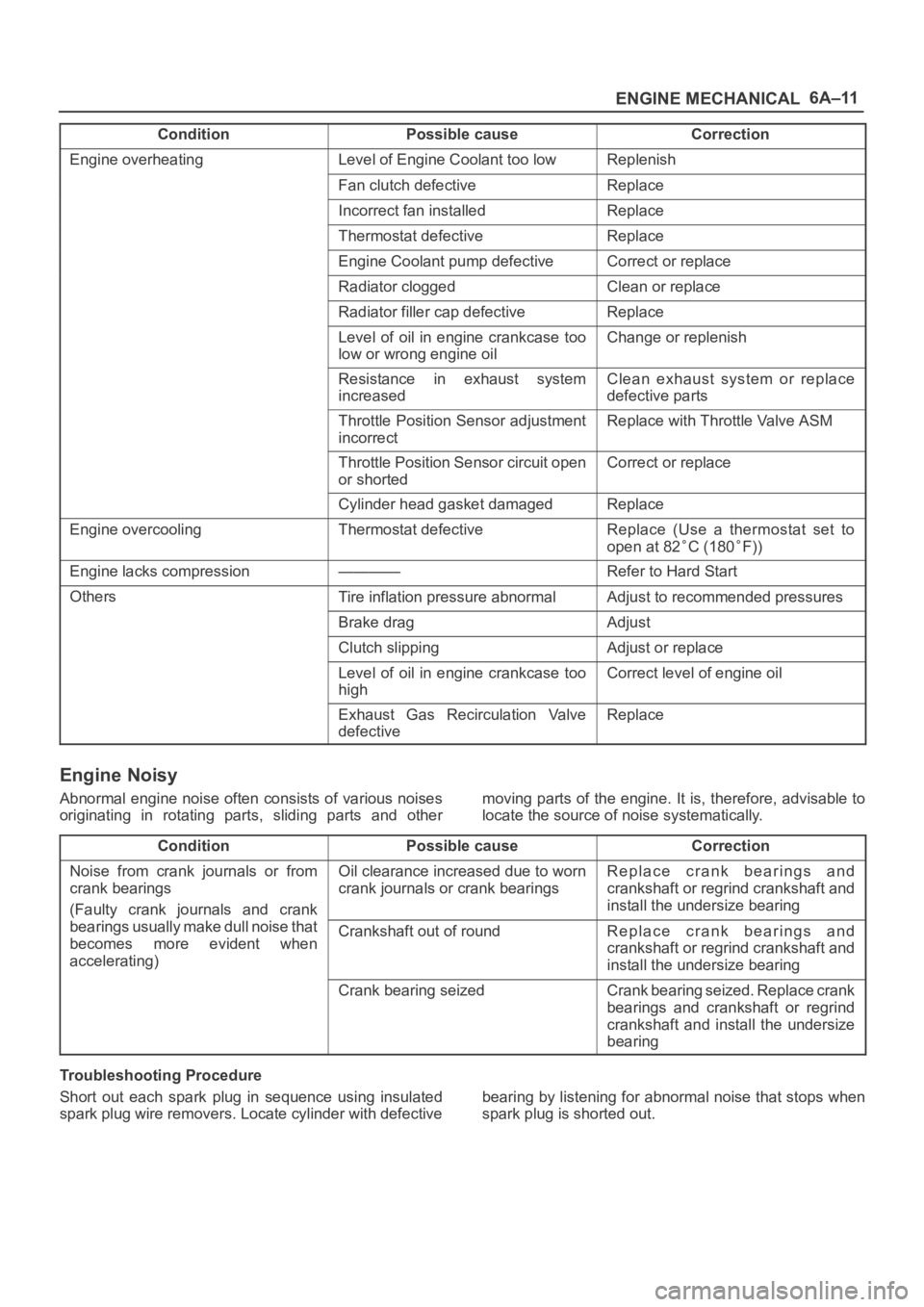
Condition CorrectionPossible cause
Engine overheatingLevel of Engine Coolant too lowReplenish
Fan clutch defectiveReplace
Incorrect fan installedReplace
Thermostat defectiveReplace
Engine Coolant pump defectiveCorrect or replace
Radiator cloggedClean or replace
Radiator filler cap defectiveReplace
Level of oil in engine crankcase too
low or wrong engine oilChange or replenish
Resistance in exhaust system
increasedClean exhaust system or replace
defective parts
Throttle Position Sensor adjustment
incorrectReplace with Throttle Valve ASM
Throttle Position Sensor circuit open
or shortedCorrect or replace
Cylinder head gasket damagedReplace
Engine overcoolingThermostat defectiveReplace (Use a thermostat set to
open at 82
C (180F))
Engine lacks compression————Refer to Hard Start
OthersTire inflation pressure abnormalAdjust to recommended pressures
Brake dragAdjust
Clutch slippingAdjust or replace
Level of oil in engine crankcase too
highCorrect level of engine oil
Exhaust Gas Recirculation Valve
defectiveReplace
Engine Noisy
Abnormal engine noise often consists of various noises
originating in rotating parts, sliding parts and othermoving parts of the engine. It is, therefore, advisable to
locate the source of noise systematically.
Condition
Possible causeCorrection
Noise from crank journals or from
crank bearings
(Faulty crank journals and crankOil clearance increased due to worn
crank journals or crank bearingsReplace crank bearings and
crankshaft or regrind crankshaft and
install the undersize bearing
yj
bearings usually make dull noise that
becomes more evident when
accelerating)Crankshaft out of roundReplace crank bearings and
crankshaft or regrind crankshaft and
install the undersize bearing
Crank bearing seizedCrank bearing seized. Replace crank
bearings and crankshaft or regrind
crankshaft and install the undersize
bearing
Troubleshooting Procedure
Short out each spark plug in sequence using insulated
spark plug wire removers. Locate cylinder with defectivebearing by listening for abnormal noise that stops when
spark plug is shorted out.
Page 4994 of 6000

6E–337 ENGINE DRIVEABILITY AND EMISSIONS
0018
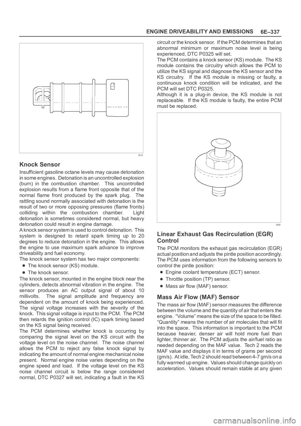
Knock Sensor
Insufficient gasoline octane levels may cause detonation
in some engines. Detonation is an uncontrolled explosion
(burn) in the combustion chamber. This uncontrolled
explosion results from a flame front opposite that of the
normal flame front produced by the spark plug. The
rattling sound normally associated with detonation is the
result of two or more opposing pressures (flame fronts)
colliding within the combustion chamber. Light
detonation is sometimes considered normal, but heavy
detonation could result in engine damage.
A knock sensor system is used to control detonation. This
system is designed to retard spark timing up to 20
degrees to reduce detonation in the engine. This allows
the engine to use maximum spark advance to improve
driveability and fuel economy.
The knock sensor system has two major components:
The knock sensor (KS) module.
The knock sensor.
The knock sensor, mounted in the engine block near the
cylinders, detects abnormal vibration in the engine. The
sensor produces an AC output signal of about 10
millivolts. The signal amplitude and frequency are
dependent on the amount of knock being experienced.
The signal voltage increases with the severity of the
knock. This signal voltage is input to the PCM. The PCM
then retards the ignition control (IC) spark timing based
on the KS signal being received.
The PCM determines whether knock is occurring by
comparing the signal level on the KS circuit with the
voltage level on the noise channel. The noise channel
allows the PCM to reject any false knock signal by
indicating the amount of normal engine mechanical noise
present. Normal engine noise varies depending on the
engine speed and load. If the voltage level on the KS
noise channel circuit is below the range considered
normal, DTC P0327 will set, indicating a fault in the KScircuit or the knock sensor. If the PCM determines that an
abnormal minimum or maximum noise level is being
experienced, DTC P0325 will set.
The PCM contains a knock sensor (KS) module. The KS
module contains the circuitry which allows the PCM to
utilize the KS signal and diagnose the KS sensor and the
KS circuitry. If the KS module is missing or faulty, a
continuous knock condition will be indicated, and the
PCM will set DTC P0325.
Although it is a plug-in device, the KS module is not
replaceable. If the KS module is faulty, the entire PCM
must be replaced.
0009
Linear Exhaust Gas Recirculation (EGR)
Control
The PCM monitors the exhaust gas recirculation (EGR)
actual position and adjusts the pintle position accordingly.
The PCM uses information from the following sensors to
control the pintle position:
Engine coolant temperature (ECT) sensor.
Throttle position (TP) sensor.
Mass air flow (MAF) sensor.
Mass Air Flow (MAF) Sensor
The mass air flow (MAF) sensor measures the difference
between the volume and the quantity of air that enters the
engine. “Volume” means the size of the space to be filled.
“Quantity” means the number of air molecules that will fit
into the space. This information is important to the PCM
because heavier, denser air will hold more fuel than
lighter, thinner air. The PCM adjusts the air/fuel ratio as
needed depending on the MAF value. Tech 2 reads the
MAF value and displays it in terms of grams per second
(gm/s). At idle, Tech 2 should read between 4-7 gm/s on a
fully warmed up engine. Values should change quickly on
acceleration. Values should remain stable at any given