1998 OPEL FRONTERA flat tire
[x] Cancel search: flat tirePage 3454 of 6000
SUPPLEMENTAL RESTRAINT SYSTEM9J–17
COOL BEFORE HANDLING ANY METAL PORTION
OF IT. DO NOT PLACE THE DEPLOYED INFLATOR
MODULE NEAR ANY FLAMMABLE OBJECTS.
FAILURE TO FOLLOW PROCEDURES MAY RESULT
IN FIRE OR PERSONAL INJURY. AFTER AN AIR BAG
ASSEMBLY HAS BEEN DEPLOYED, THE METAL
CANISTER AND SURROUNDING AREAS OF THE AIR
BAG ASSEMBLY WILL BE HOT. DO NOT TOUCH THE
METAL AREAS OF THE AIR BAG ASSEMBLY FOR
ABOUT THIRTY MINUTES AFTER DEPLOYMENT. IF
THE DEPLOYED AIR BAG ASSEMBLY MUST BE
MOVED BEFORE IT IS COOL, WEAR GLOVES AND
HANDLE BY THE AIR BAG ITSELF.
21. Disconnect the pigtail adapter from the air bag
assembly as soon after deployment as possible to
avoid damage to the pigtail adapter or SRS
deployment harness from contacting the hot air bag
assembly canister. The pigtail adapter and SRS
deployment harness are designed to be reused.
They should, however, be inspected for damage after
each deployment and replaced if necessary.
22. Dispose of the deployed air bag assembly through
normal refuse channels after it has cooled for at least
30 minutes.
23. Wash your hands with mild soap and water afterward.
NOTE: The remaining steps are to be followed in the
unlikely event that the air bag assembly did not deploy
after following the above procedures.
24. Ensure that the SRS deployment harness has been
disconnected from the power source and that its two
banana plugs have been shorted together by fully
seating one banana plug into the other.
25. Disconnect the pigtail adapter from the air bag
assembly.
WARNING: WHEN STORING A LIVE AIR BAG
ASSEMBLY OR WHEN LEAVING A LIVE AIR BAG
ASSEMBLY UNATTENDED ON A BENCH OR OTHER
SURFACE, ALWAYS FACE THE BAG UP AND AWAY
FROM THE SURFACE. THIS IS NECESSARY SO
THAT A FREE SPACE IS PROVIDED TO ALLOW THE
AIR BAG TO EXPAND IN THE UNLIKELY EVENT OF
ACCIDENTAL DEPLOYMENT. FAILURE TO FOLLOW
PROCEDURES MAY RESULT IN PERSONAL INJURY.
26. Temporarily store the air bag assembly with the bag
facing up, away from the surface upon which it rests.
Deployment Outside Vehicle (Fixing Air
Bag on Tire)
Read and understand the items of “CAUTIONS ABOUT
AIR BAG DEPLOYMENT AND DISPOSAL
PROCEDURES” and “Usage of Deployment Tool” for
safe deployment of air bag.
1. Remove air bag assembly from vehicle. Refer to air
bag assembly Removal “in this section”.2. Inspect J–41434 Supplemental Restraint System
(SRS) Deployment Harness and appropriate pigtail
adapter for damage. If harness or pigtail is damaged,
discard and obtain a replacement.
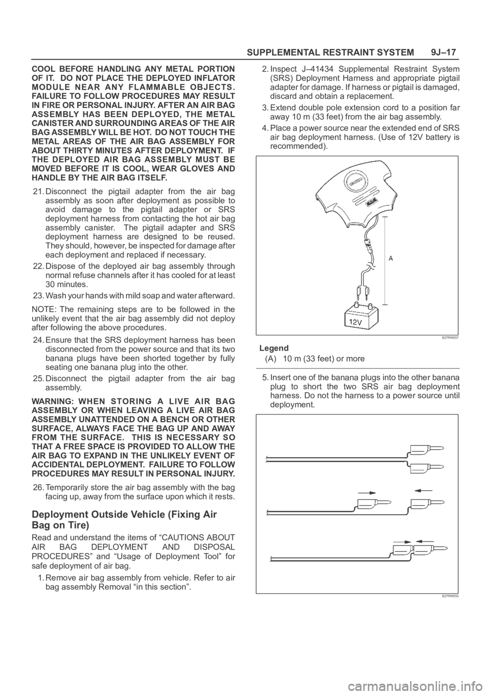
3. Extend double pole extension cord to a position far
away 10 m (33 feet) from the air bag assembly.
4. Place a power source near the extended end of SRS
air bag deployment harness. (Use of 12V battery is
recommended).
827RW057
Legend
(A) 10 m (33 feet) or more
5. Insert one of the banana plugs into the other banana
plug to short the two SRS air bag deployment
harness. Do not the harness to a power source until
deployment.
827RW055
Page 3456 of 6000
SUPPLEMENTAL RESTRAINT SYSTEM9J–19
NOTE: Ensure that the pigtail adapter is firmly seated into
the air bag assembly connector. Failure to fully seat the
connectors may leave the shorting bar located in the air
bag assembly connector functioning (shorting the
deployment circuit) and may result in non deployment of
the air bag assembly.
827RW054
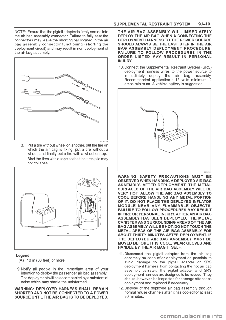
3. Put a tire without wheel on another, put the tire on
which the air bag is fixing, put a tire without a
wheel, and finally put a tire with a wheel on top.
Bind the tires with a rope so that the tires pile may
not collapse.
827RW050
Legend
(A) 10 m (33 feet) or more
9. Notify all people in the immediate area of your
intention to deploy the passenger air bag assembly.
The deployment will be accompanied by a substantial
noise which may startle the uninformed.
WARNING: DEPLOYED HARNESS SHALL REMAIN
SHORTED AND NOT BE CONNECTED TO A POWER
SOURCE UNTIL THE AIR BAG IS TO BE DEPLOYED.THE AIR BAG ASSEMBLY WILL IMMEDIATELY
DEPLOY THE AIR BAG WHEN A CONNECTING THE
DEPLOYMENT HARNESS TO THE POWER SOURCE
SHOULD ALWAYS BE THE LAST STEP IN THE AIR
BAG ASSEMBLY DEPLOYMENT PROCEDURE.
FAILURE TO FOLLOW PROCEDURES IN THE
ORDER LISTED MAY RESULT IN PERSONAL
INJURY.
10. Connect the Supplemental Restraint System (SRS)
deployment harness wires to the power source to
immediately deploy the air bag assembly.
Recommended application : 12 volts minimum, 2
amps minimum. A vehicle battery is suggested.
827LW011
WARNING: SAFETY PRECAUTIONS MUST BE
OBSERVED WHEN HANDING A DEPLOYED AIR BAG
ASSEMBLY. AFTER DEPLOYMENT, THE METAL
SURFACES OF THE AIR BAG ASSEMBLY WILL BE
VERY HOT. ALLOW THE AIR BAG ASSEMBLY TO
COOL BEFORE HANDLING ANY METAL PORTION
OF IT. DO NOT PLACE THE DEPLOYED INFLATOR
MODULE NEAR ANY FLAMMABLE OBJECTS.
FAILURE TO FOLLOW PROCEDURES MAY RESULT
I N F IR E O R PE RSO NAL IN JU RY. A FT ER A N A IR BAG
ASSEMBLY HAS BEEN DEPLOYED, THE METAL
CANISTER AND SURROUNDING AREAS OF THE AIR
BAG ASSEMBLY WILL BE HOT. DO NOT TOUCH THE
METAL AREAS OF THE AIR BAG ASSEMBLY FOR
ABOUT THIRTY MINUTES AFTER DEPLOYMENT. IF
THE DEPLOYED AIR BAG ASSEMBLY MUST BE
MOVED BEFORE IT IS COOL, WEAR GLOVES AND
HANDLE BY THE AIR BAG IT SELF.
11. Disconnect the pigtail adapter from the air bag
assembly as soon after deployment as possible to
avoid damage to the pigtail adapter or SRS
deployment harness from contacting the hot air bag
assembly canister. The pigtail adapter and SRS
deployment harness are designed to be reused. They
should, however, be inspected for damage after each
deployment and replaced if necessary.
12. Dispose of the deployed air bag assembly through
normal refuse channels after it has cooled for at least
30 minutes.
Page 3458 of 6000
SUPPLEMENTAL RESTRAINT SYSTEM9J–21
THROUGHOUT THIS ENTIRE DEPLOYMENT AND
DISPOSAL PROCEDURE.
9. Twist together one connector wire lead to one
deployment wire. The connection should be
mechanically secure.
10. Bend twisted connection made in the previous step
flat and wrap tightly with electrical tape to insulate and
secure.
11. Twist together, bend and tape the remaining
connector wire lead to the remaining deployment
wire.
12. Connect the deployment harness to the driver air bag
assembly, yellow 2–pin connector at the base of the
steering column. Route deployment harness out the
driver side of the vehicle.
WARNING: DEPLOYMENT WIRES SHALL REMAIN
SHORTED AND NOT BE CONNECTED TO A POWER
SOURCE UNTIL THE AIR BAG IS TO BE DEPLOYED.
THE AIR BAG ASSEMBLY WILL IMMEDIATELY
DEPLOY THE AIR BAG WHEN A POWER SOURCE IS
CONNECTED TO IT.
CONNECTING THE DEPLOYMENT WIRES TO THE
POWER SOURCE SHOULD ALWAYS BE THE FINAL
STEP IN THE AIR BAG ASSEMBLY DEPLOYMENT
PROCEDURE.
FAILURE TO FOLLOW PROCEDURES IN THE
ORDER LISTED COULD RESULT IN PERSONAL
INJURY.
13. Disconnect passenger air bag assembly, yellow 2–pin
connector located behind glove box assembly.
14. Cut the passenger air bag assembly harness
connector from the vehicle leaving at least 15 cm (six
inches) of wire at the connector.
15. Strip 13 mm (1/2 inch) of insulation from blue–white
and pink–blue wire lead of the connector.
16. Cut two 900 cm (30 feet) deployment wires from 0.8
mm
(18 gauge) or thicker multi–strand wire. These
wires will be used to fabricate the passenger
deployment harness.
17. Strip 13 mm (1/2 inch) of insulation from both ends of
the wires cut in the previous step.
18. Short the wires by twisting together one end from
each. Deployment wires shall remain shorted and not
be connected to a power source until the air bag is to
be deployed.
WARNING: FAILURE TO FOLLOW PROCEDURES IN
THE ORDER LISTED COULD RESULT IN PERSONAL
INJURY. NEVER CONNECT DEPLOYMENT WIRES
TO ANY POWER SOURCE BEFORE CONNECTING
DEPLOYMENT WIRES TO THE AIR BAG ASSEMBLY
LEADS. DEPLOYMENT WIRES SHALL REMAIN
SHORTED AND NOT BE CONNECTED TO A POWER
SOURCE UNTIL THE AIR BAG IS TO BE DEPLOYED.
THE AIR BAG ASSEMBLY WILL IMMEDIATELY
DEPLOY THE AIR BAG WHEN A POWER SOURCE IS
CONNECTED TO IT. WEAR SAFETY GLASSES
THROUGHOUT THIS ENTIRE DEPLOYMENT AND
DISPOSAL PROCEDURE.19. Twist together one connector wire lead to one
deployment wire. The connection should be
mechanically secure.
20. Bend twisted connection made in the previous step
flat and wrap tightly with electrical tape to insulate and
secure.
21. Twist together, bend and tape the remaining
connector wire lead to the remaining deployment
wire.
22. Connect the deployment harness to the passenger air
bag assembly, yellow 2–pin connector located behind
the glove box assembly. Route deployment harness
out the passenger side of the vehicle.
WARNING: DEPLOYMENT WIRES SHALL REMAIN
SHORTED AND NOT BE CONNECTED TO A POWER
SOURCE UNTIL THE AIR BAG IS TO BE DEPLOYED.
THE AIR BAG ASSEMBLY WILL IMMEDIATELY
DEPLOY THE AIR BAG WHEN A POWER SOURCE IS
CONNECTED TO IT. CONNECTING THE
DEPLOYMENT WIRES SHOULD ALWAYS BE THE
FINAL STEP IN THE AIR BAG ASSEMBLY
DEPLOYMENT PROCEDURE. FAILURE TO FOLLOW
PROCEDURES IN THE ORDER LISTED COULD
RESULT IN PERSONAL INJURY.
23. Verify that the inside of the vehicle and the area
surrounding the vehicle are clear of all people and
loose or flammable objects.
24. Stretch the driver and passenger deployment
harness to their full length.
25. Completely cover windshield area and front door
window openings with a drop cloth, blanket or similar
item. This reduces the possibility of injury due to
possible fragmentation of the vehicle’s glass or
interior.
26. Notify all people in the immediate area that you intend
to deploy the air bags. The deployment will be
accompanied by a substantial noise which may
startle the uninformed.
27. Separate the two ends of the driver deployment
harness wires.
WARNING: DEPLOYMENT WIRES SHALL REMAIN
SHORTED AND NOT BE CONNECTED TO A POWER
SOURCE UNTIL THE AIR BAG IS TO A POWER
SOURCE UNTIL THE AIR BAG IS TO BE DEPLOYED.
THE AIR BAG ASSEMBLY WILL IMMEDIATELY
DEPLOY THE AIR BAG WHEN A POWER SOURCE IS
CONNECTED TO IT. CONNECTING THE
DEPLOYMENT WIRES TO THE POWER SOURCE
SHOULD ALWAYS BE THE FINAL STEP IN THE AIR
BAG ASSEMBLY DEPLOYMENT PROCEDURE.
FAILURE TO FOLLOW PROCEDURES IN THE
ORDER LISTED COULD RESULT IN PERSONAL
INJURY.
NOTE: When the air bag deploys, the rapid gas
expansion will create a substantial noise. Notify all
people in the immediate area that you intend to deploy the
air bags.
Page 3459 of 6000
SUPPLEMENTAL RESTRAINT SYSTEM 9J–22
28. Connect the driver deployment harness wires to a
power source to immediately deploy the driver air bag
assembly. Recommended application: 12 volts
minimum, 2 amps minimum. A vehicle battery is
suggested.
29. Separate the two ends of the passenger deployment
harness wires.
WARNING: DEPLOYMENT WIRES SHALL REMAIN
SHORTED AND NOT BE CONNECTED TO A POWER
SOURCE UNTIL THE AIR BAG IS TO A POWER
SOURCE UNTIL THE AIR BAG IS TO BE DEPLOYED.
THE AIR BAG ASSEMBLY WILL IMMEDIATELY
DEPLOY THE AIR BAG WHEN A POWER SOURCE IS
CONNECTED TO IT. CONNECTING THE
DEPLOYMENT WIRES TO THE POWER SOURCE
SHOULD ALWAYS BE THE FINAL STEP IN THE AIR
BAG ASSEMBLY DEPLOYMENT PROCEDURE.
FAILURE TO FOLLOW PROCEDURES IN THE
ORDER LISTED COULD RESULT IN PERSONAL
INJURY.
30. Connect the passenger deployment harness wires to
a power source to immediately deploy the passenger
air bag assembly. Recommended application: 12
volts minimum, 2 amps minimum. A vehicle battery is
suggested.(Driver air bag assembly) Put on a pair of
shop gloves and safety glasses to protect your hands
and eyes from possible irritation and heat when
handling the deployed air bag assembly. After the air
bag assembly has been deployed, the surface of the
air bag may contain solid particulate. This solid
particulate consists primarily of by products of the
chemical reaction, Potassium Chloride and copper
metal dust. Compounds of Potassium Borate,
Strontium Chloride, Copper Chloride, and
Ammonium Chloride may be found in amounts of
about 1 % (each) of the total particulate.
(Passenger air bag assembly)
Put on a pair of shop gloves and safety glasses to
protect your hands and eyes from possible irritation
and heat when handling the deployed air bag
assembly.
After the air bag assembly has been deployed, the
surface of the air bag may contain a powdery residue.
This powder consists primarily of cornstarch (used to
lubricate the bag as it inflates) and by products of the
chemical reaction. Sodium hydroxide dust (similar to
lye soap) is produced as a by product of the
deployment reaction. The sodium hydroxide then
quickly reacts with atmospheric moisture and is
converted to sodium carbonate and sodium
bicarbonate (baking soda). Therefore, it is unlikely
that sodium hydroxide will be present after
deployment.
WARNING: SAFETY PRECAUTIONS MUST BE
OBSERVED WHEN HANDLING A DEPLOYED AIR
BAG ASSEMBLY. AFTER DEPLOYMENT, THE
METAL SURFACES OF THE AIR BAG ASSEMBLY
WILL BE VERY HOT. ALLOW THE AIR BAG
ASSEMBLY TO COOL BEFORE HANDLING ANY
METAL PORTION OF IT. DO NOT PLACE THE HOT
DEPLOYED AIR BAG ASSEMBLY NEAR ANY
FLAMMABLE OBJECTS. FAILURE TO FOLLOWPROCEDURES COULD RESULT IN FIRE OR
PERSONAL INJURY.
After an air bag assembly has been deployed, the
metal canister and surrounding areas of the air bag
assembly will be very hot. Do not touch the metal
areas of the air bag assembly for about 30 minutes
after deployment. If the deployed air bag assembly
must be moved before it is cool, wear gloves and
handle by the air bag or trim cover.
31. Short the driver deployment harness wires by twisting
together one end from each. Repeat this procedure
for the passenger deployment harness.
32. Carefully remove drop cloth from vehicle and clean off
any fragments or discard drop cloth entirely.
33. Disconnect driver deployment harness and
passenger deployment harness from vehicle and
discard.
34. In the unlikely event that either or both of the air bag
assemblies did not deploy after following these
procedures, proceed immediately with Steps 36
through 37. If the air bag assembly deployed, proceed
to step 35.
35. With both air bags deployed, the vehicle may be
scrapped in the same manner as a non–SRS
equipped vehicle.
NOTE: The remaining steps are to be followed in the
unlikely event that the air bag assembly did not deploy
after following these procedures.
36. Remove the undeployed air bag assembly (s) from
the vehicle. For driver air bag assembly refer to in the
“Passenger Air Bag Assembly Removal” in this
manual.
WARNING: W H E N S T O R I N G A L I V E A I R B A G
ASSEMBLY OR WHEN LEAVING A LIVE AIR BAG
ASSEMBLY UNATTENDED ON A BENCH OR OTHER
SURFACE, ALWAYS FACE THE BAG AND TRIM
COVER UP, AWAY FROM THE SURFACE. THIS IS
NECESSARY SO THAT A FREE SPACE IS PROVIDED
TO ALLOW THE AIR BAG TO EXPAND IN THE
UNLIKELY EVENT OF ACCIDENTAL DEPLOYMENT.
FAILURE TO FOLLOW PROCEDURES COULD
RESULT IN PERSONAL INJURY.
37. Temporarily store the air bag assembly with the air
bag opening facing up, away from the surface upon
which it rests.
Deployed Air Bag Assembly Handling
Put on a pair of shop gloves and safety glasses to protect
your hands and eyes from possible irritation and heat
when handling the deployed air bag assembly.
After the air bag assembly has been deployed, the
surface of the air bag may contain a powdery residue.
(Passenger air bag assembly)
After the air bag assembly has been deployed, the
surface of the air bag may contain a powdery residue.
This powder consists primarily of cornstarch (used to
lubricate the bag as it inflates) and by products of the
chemical reaction. Sodium hydroxide dust (similar to lye
soap) is produced as a by product of the deployment
reaction. The sodium hydroxide then quickly reacts with
atmospheric moisture and is converted to sodium
Page 3942 of 6000
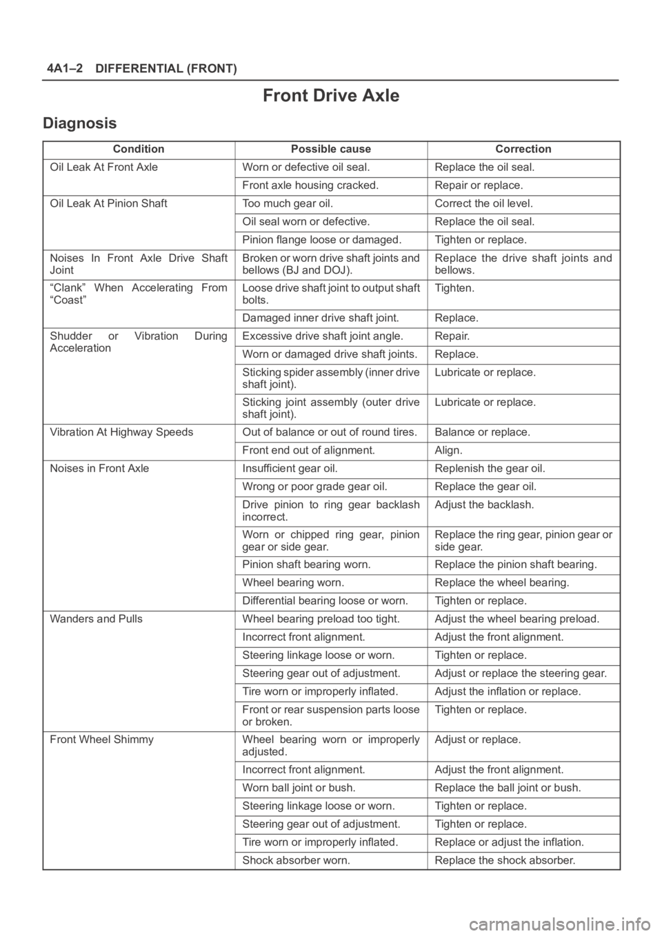
DIFFERENTIAL (FRONT) 4A1–2
Front Drive Axle
Diagnosis
ConditionPossible causeCorrection
Oil Leak At Front AxleWorn or defective oil seal.Replace the oil seal.
Front axle housing cracked.Repair or replace.
Oil Leak At Pinion ShaftToo much gear oil.Correct the oil level.
Oil seal worn or defective.Replace the oil seal.
Pinion flange loose or damaged.Tighten or replace.
Noises In Front Axle Drive Shaft
JointBroken or worn drive shaft joints and
bellows (BJ and DOJ).Replace the drive shaft joints and
bellows.
“Clank” When Accelerating From
“Coast”Loose drive shaft joint to output shaft
bolts.Tighten.
Damaged inner drive shaft joint.Replace.
Shudder or Vibration During
Acceleration
Excessive drive shaft joint angle.Repair.
AccelerationWorn or damaged drive shaft joints.Replace.
Sticking spider assembly (inner drive
shaft joint).Lubricate or replace.
Sticking joint assembly (outer drive
shaft joint).Lubricate or replace.
Vibration At Highway SpeedsOut of balance or out of round tires.Balance or replace.
Front end out of alignment.Align.
Noises in Front AxleInsufficient gear oil.Replenish the gear oil.
Wrong or poor grade gear oil.Replace the gear oil.
Drive pinion to ring gear backlash
incorrect.Adjust the backlash.
Worn or chipped ring gear, pinion
gear or side gear.Replace the ring gear, pinion gear or
side gear.
Pinion shaft bearing worn.Replace the pinion shaft bearing.
Wheel bearing worn.Replace the wheel bearing.
Differential bearing loose or worn.Tighten or replace.
Wanders and PullsWheel bearing preload too tight.Adjust the wheel bearing preload.
Incorrect front alignment.Adjust the front alignment.
Steering linkage loose or worn.Tighten or replace.
Steering gear out of adjustment.Adjust or replace the steering gear.
Tire worn or improperly inflated.Adjust the inflation or replace.
Front or rear suspension parts loose
or broken.Tighten or replace.
Front Wheel ShimmyWheel bearing worn or improperly
adjusted.Adjust or replace.
Incorrect front alignment.Adjust the front alignment.
Worn ball joint or bush.Replace the ball joint or bush.
Steering linkage loose or worn.Tighten or replace.
Steering gear out of adjustment.Tighten or replace.
Tire worn or improperly inflated.Replace or adjust the inflation.
Shock absorber worn.Replace the shock absorber.
Page 3972 of 6000
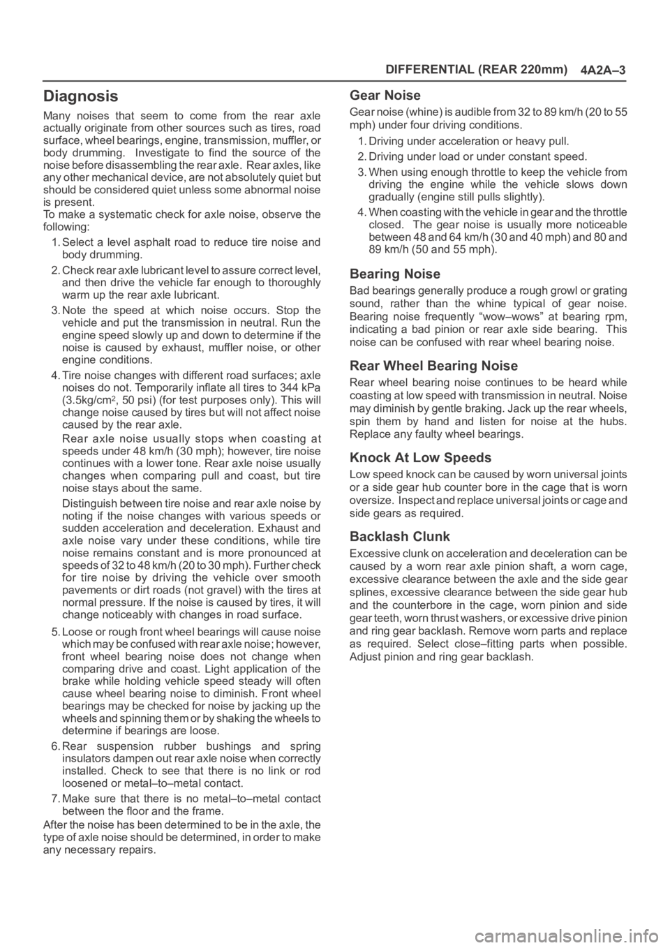
DIFFERENTIAL (REAR 220mm)
4A2A–3
Diagnosis
Many noises that seem to come from the rear axle
actually originate from other sources such as tires, road
surface, wheel bearings, engine, transmission, muffler, or
body drumming. Investigate to find the source of the
noise before disassembling the rear axle. Rear axles, like
any other mechanical device, are not absolutely quiet but
should be considered quiet unless some abnormal noise
is present.
To make a systematic check for axle noise, observe the
following:
1. Select a level asphalt road to reduce tire noise and
body drumming.
2. Check rear axle lubricant level to assure correct level,
and then drive the vehicle far enough to thoroughly
warm up the rear axle lubricant.
3. Note the speed at which noise occurs. Stop the
vehicle and put the transmission in neutral. Run the
engine speed slowly up and down to determine if the
noise is caused by exhaust, muffler noise, or other
engine conditions.
4. Tire noise changes with different road surfaces; axle
noises do not. Temporarily inflate all tires to 344 kPa
(3.5kg/cm
2, 50 psi) (for test purposes only). This will
change noise caused by tires but will not affect noise
caused by the rear axle.
Rear axle noise usually stops when coasting at
speeds under 48 km/h (30 mph); however, tire noise
continues with a lower tone. Rear axle noise usually
changes when comparing pull and coast, but tire
noise stays about the same.
Distinguish between tire noise and rear axle noise by
noting if the noise changes with various speeds or
sudden acceleration and deceleration. Exhaust and
axle noise vary under these conditions, while tire
noise remains constant and is more pronounced at
speeds of 32 to 48 km/h (20 to 30 mph). Further check
for tire noise by driving the vehicle over smooth
pavements or dirt roads (not gravel) with the tires at
normal pressure. If the noise is caused by tires, it will
change noticeably with changes in road surface.
5. Loose or rough front wheel bearings will cause noise
which may be confused with rear axle noise; however,
front wheel bearing noise does not change when
comparing drive and coast. Light application of the
brake while holding vehicle speed steady will often
cause wheel bearing noise to diminish. Front wheel
bearings may be checked for noise by jacking up the
wheels and spinning them or by shaking the wheels to
determine if bearings are loose.
6. Rear suspension rubber bushings and spring
insulators dampen out rear axle noise when correctly
installed. Check to see that there is no link or rod
loosened or metal–to–metal contact.
7. Make sure that there is no metal–to–metal contact
between the floor and the frame.
After the noise has been determined to be in the axle, the
type of axle noise should be determined, in order to make
any necessary repairs.
Gear Noise
Gear noise (whine) is audible from 32 to 89 km/h (20 to 55
mph) under four driving conditions.
1. Driving under acceleration or heavy pull.
2. Driving under load or under constant speed.
3. When using enough throttle to keep the vehicle from
driving the engine while the vehicle slows down
gradually (engine still pulls slightly).
4. When coasting with the vehicle in gear and the throttle
closed. The gear noise is usually more noticeable
between 48 and 64 km/h (30 and 40 mph) and 80 and
89 km/h (50 and 55 mph).
Bearing Noise
Bad bearings generally produce a rough growl or grating
sound, rather than the whine typical of gear noise.
Bearing noise frequently “wow–wows” at bearing rpm,
indicating a bad pinion or rear axle side bearing. This
noise can be confused with rear wheel bearing noise.
Rear Wheel Bearing Noise
Rear wheel bearing noise continues to be heard while
coasting at low speed with transmission in neutral. Noise
may diminish by gentle braking. Jack up the rear wheels,
spin them by hand and listen for noise at the hubs.
Replace any faulty wheel bearings.
Knock At Low Speeds
Low speed knock can be caused by worn universal joints
or a side gear hub counter bore in the cage that is worn
oversize. Inspect and replace universal joints or cage and
side gears as required.
Backlash Clunk
Excessive clunk on acceleration and deceleration can be
caused by a worn rear axle pinion shaft, a worn cage,
excessive clearance between the axle and the side gear
splines, excessive clearance between the side gear hub
and the counterbore in the cage, worn pinion and side
gear teeth, worn thrust washers, or excessive drive pinion
and ring gear backlash. Remove worn parts and replace
as required. Select close–fitting parts when possible.
Adjust pinion and ring gear backlash.
Page 4011 of 6000
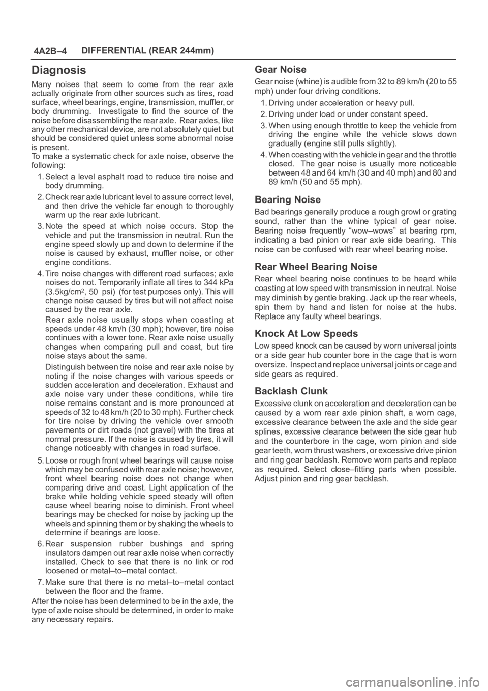
4A2B–4DIFFERENTIAL (REAR 244mm)
Diagnosis
Many noises that seem to come from the rear axle
actually originate from other sources such as tires, road
surface, wheel bearings, engine, transmission, muffler, or
body drumming. Investigate to find the source of the
noise before disassembling the rear axle. Rear axles, like
any other mechanical device, are not absolutely quiet but
should be considered quiet unless some abnormal noise
is present.
To make a systematic check for axle noise, observe the
following:
1. Select a level asphalt road to reduce tire noise and
body drumming.
2. Check rear axle lubricant level to assure correct level,
and then drive the vehicle far enough to thoroughly
warm up the rear axle lubricant.
3. Note the speed at which noise occurs. Stop the
vehicle and put the transmission in neutral. Run the
engine speed slowly up and down to determine if the
noise is caused by exhaust, muffler noise, or other
engine conditions.
4. Tire noise changes with different road surfaces; axle
noises do not. Temporarily inflate all tires to 344 kPa
(3.5kg/cm
2, 50 psi) (for test purposes only). This will
change noise caused by tires but will not affect noise
caused by the rear axle.
Rear axle noise usually stops when coasting at
speeds under 48 km/h (30 mph); however, tire noise
continues with a lower tone. Rear axle noise usually
changes when comparing pull and coast, but tire
noise stays about the same.
Distinguish between tire noise and rear axle noise by
noting if the noise changes with various speeds or
sudden acceleration and deceleration. Exhaust and
axle noise vary under these conditions, while tire
noise remains constant and is more pronounced at
speeds of 32 to 48 km/h (20 to 30 mph). Further check
for tire noise by driving the vehicle over smooth
pavements or dirt roads (not gravel) with the tires at
normal pressure. If the noise is caused by tires, it will
change noticeably with changes in road surface.
5. Loose or rough front wheel bearings will cause noise
which may be confused with rear axle noise; however,
front wheel bearing noise does not change when
comparing drive and coast. Light application of the
brake while holding vehicle speed steady will often
cause wheel bearing noise to diminish. Front wheel
bearings may be checked for noise by jacking up the
wheels and spinning them or by shaking the wheels to
determine if bearings are loose.
6. Rear suspension rubber bushings and spring
insulators dampen out rear axle noise when correctly
installed. Check to see that there is no link or rod
loosened or metal–to–metal contact.
7. Make sure that there is no metal–to–metal contact
between the floor and the frame.
After the noise has been determined to be in the axle, the
type of axle noise should be determined, in order to make
any necessary repairs.
Gear Noise
Gear noise (whine) is audible from 32 to 89 km/h (20 to 55
mph) under four driving conditions.
1. Driving under acceleration or heavy pull.
2. Driving under load or under constant speed.
3. When using enough throttle to keep the vehicle from
driving the engine while the vehicle slows down
gradually (engine still pulls slightly).
4. When coasting with the vehicle in gear and the throttle
closed. The gear noise is usually more noticeable
between 48 and 64 km/h (30 and 40 mph) and 80 and
89 km/h (50 and 55 mph).
Bearing Noise
Bad bearings generally produce a rough growl or grating
sound, rather than the whine typical of gear noise.
Bearing noise frequently “wow–wows” at bearing rpm,
indicating a bad pinion or rear axle side bearing. This
noise can be confused with rear wheel bearing noise.
Rear Wheel Bearing Noise
Rear wheel bearing noise continues to be heard while
coasting at low speed with transmission in neutral. Noise
may diminish by gentle braking. Jack up the rear wheels,
spin them by hand and listen for noise at the hubs.
Replace any faulty wheel bearings.
Knock At Low Speeds
Low speed knock can be caused by worn universal joints
or a side gear hub counter bore in the cage that is worn
oversize. Inspect and replace universal joints or cage and
side gears as required.
Backlash Clunk
Excessive clunk on acceleration and deceleration can be
caused by a worn rear axle pinion shaft, a worn cage,
excessive clearance between the axle and the side gear
splines, excessive clearance between the side gear hub
and the counterbore in the cage, worn pinion and side
gear teeth, worn thrust washers, or excessive drive pinion
and ring gear backlash. Remove worn parts and replace
as required. Select close–fitting parts when possible.
Adjust pinion and ring gear backlash.
Page 4199 of 6000
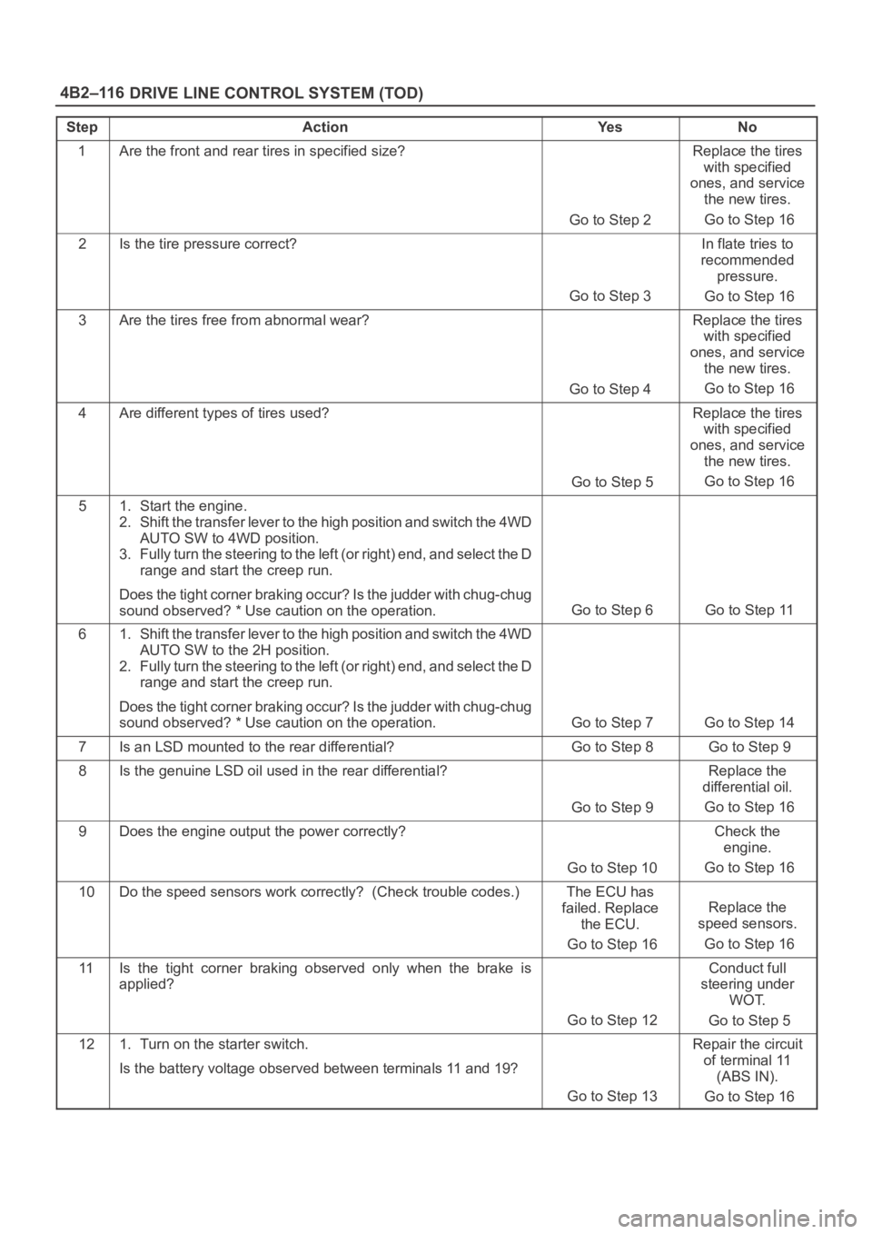
DRIVE LINE CONTROL SYSTEM (TOD) 4B2–116
StepActionYe sNo
1Are the front and rear tires in specified size?
Go to Step 2
Replace the tires
with specified
ones, and service
the new tires.
Go to Step 16
2Is the tire pressure correct?
Go to Step 3
In flate tries to
recommended
pressure.
Go to Step 16
3Are the tires free from abnormal wear?
Go to Step 4
Replace the tires
with specified
ones, and service
the new tires.
Go to Step 16
4Are different types of tires used?
Go to Step 5
Replace the tires
with specified
ones, and service
the new tires.
Go to Step 16
51. Start the engine.
2. Shift the transfer lever to the high position and switch the 4WD
AUTO SW to 4WD position.
3. Fully turn the steering to the left (or right) end, and select the D
range and start the creep run.
Does the tight corner braking occur? Is the judder with chug-chug
sound observed? * Use caution on the operation.
Go to Step 6 Go to Step 11
61. Shift the transfer lever to the high position and switch the 4WD
AUTO SW to the 2H position.
2. Fully turn the steering to the left (or right) end, and select the D
range and start the creep run.
Does the tight corner braking occur? Is the judder with chug-chug
sound observed? * Use caution on the operation.
Go to Step 7 Go to Step 14
7Is an LSD mounted to the rear differential? Go to Step 8 Go to Step 9
8Is the genuine LSD oil used in the rear differential?
Go to Step 9
Replace the
differential oil.
Go to Step 16
9Does the engine output the power correctly?
Go to Step 10
Check the
engine.
Go to Step 16
10Do the speed sensors work correctly? (Check trouble codes.)The ECU has
failed. Replace
the ECU.
Go to Step 16
Replace the
speed sensors.
Go to Step 16
11Is the tight corner braking observed only when the brake is
applied?
Go to Step 12
Conduct full
steering under
WOT.
Go to Step 5
121. Turn on the starter switch.
Is the battery voltage observed between terminals 11 and 19?
Go to Step 13
Repair the circuit
of terminal 11
(ABS IN).
Go to Step 16