1998 OPEL FRONTERA clutch
[x] Cancel search: clutchPage 2243 of 6000
7A–89 AUTOMATIC TRANSMISSION (4L30–E)
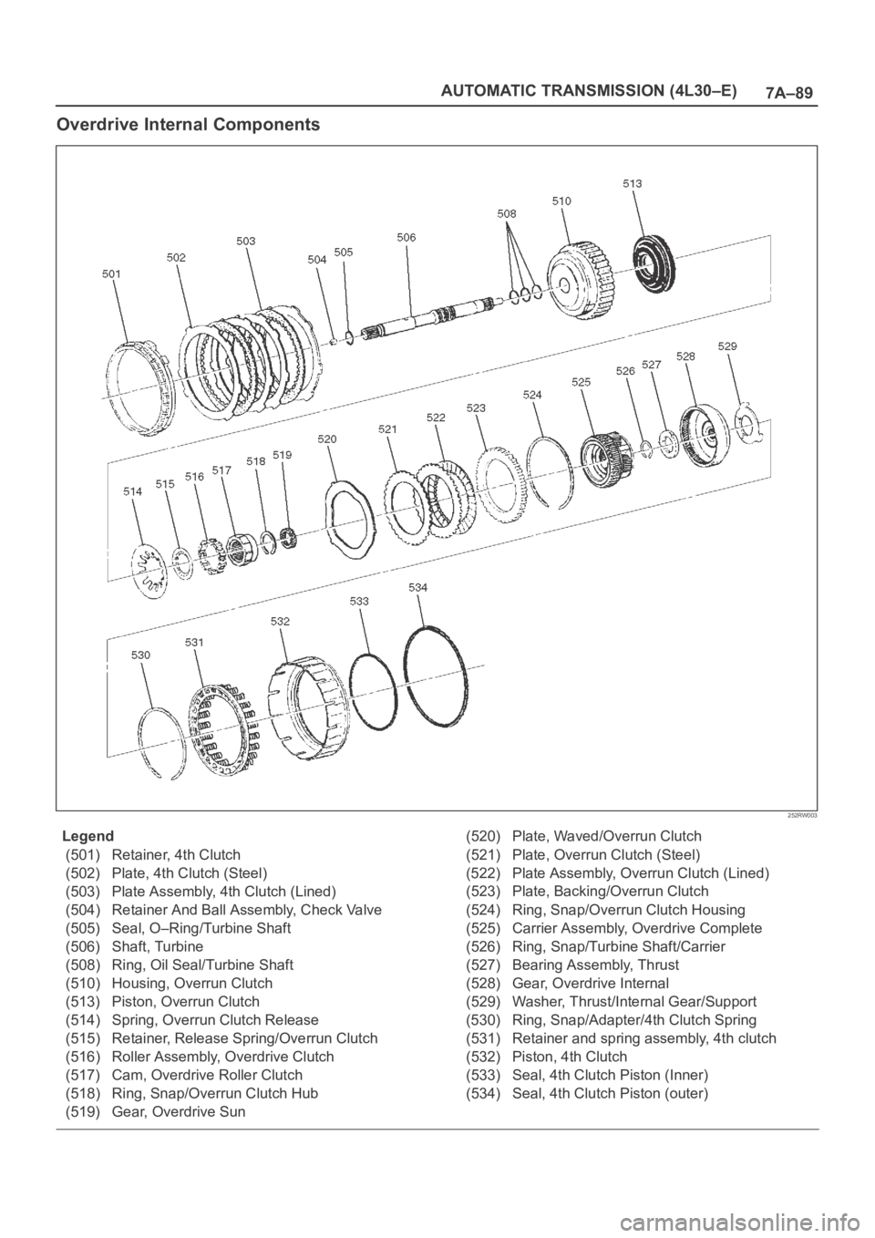
Overdrive Internal Components
252RW003
Legend
(501) Retainer, 4th Clutch
(502) Plate, 4th Clutch (Steel)
(503) Plate Assembly, 4th Clutch (Lined)
(504) Retainer And Ball Assembly, Check Valve
(505) Seal, O–Ring/Turbine Shaft
(506) Shaft, Turbine
(508) Ring, Oil Seal/Turbine Shaft
(510) Housing, Overrun Clutch
(513) Piston, Overrun Clutch
(514) Spring, Overrun Clutch Release
(515) Retainer, Release Spring/Overrun Clutch
(516) Roller Assembly, Overdrive Clutch
(517) Cam, Overdrive Roller Clutch
(518) Ring, Snap/Overrun Clutch Hub
(519) Gear, Overdrive Sun(520) Plate, Waved/Overrun Clutch
(521) Plate, Overrun Clutch (Steel)
(522) Plate Assembly, Overrun Clutch (Lined)
(523) Plate, Backing/Overrun Clutch
(524) Ring, Snap/Overrun Clutch Housing
(525) Carrier Assembly, Overdrive Complete
(526) Ring, Snap/Turbine Shaft/Carrier
(527) Bearing Assembly, Thrust
(528) Gear, Overdrive Internal
(529) Washer, Thrust/Internal Gear/Support
(530) Ring, Snap/Adapter/4th Clutch Spring
(531) Retainer and spring assembly, 4th clutch
(532) Piston, 4th Clutch
(533) Seal, 4th Clutch Piston (Inner)
(534) Seal, 4th Clutch Piston (outer)
Page 2244 of 6000
7A–90
AUTOMATIC TRANSMISSION (4L30–E)
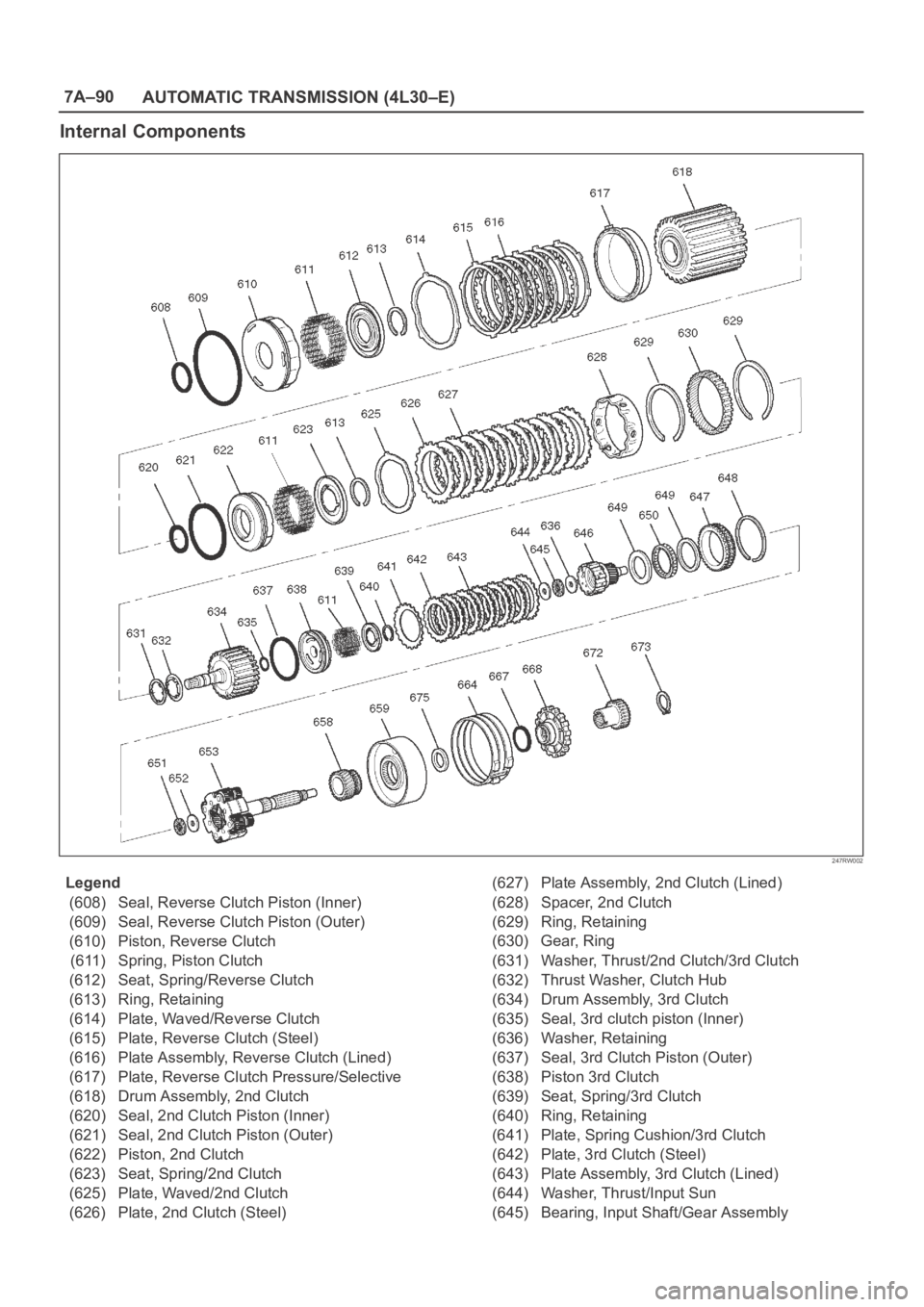
Internal Components
247RW002
Legend
(608) Seal, Reverse Clutch Piston (Inner)
(609) Seal, Reverse Clutch Piston (Outer)
(610) Piston, Reverse Clutch
(611) Spring, Piston Clutch
(612) Seat, Spring/Reverse Clutch
(613) Ring, Retaining
(614) Plate, Waved/Reverse Clutch
(615) Plate, Reverse Clutch (Steel)
(616) Plate Assembly, Reverse Clutch (Lined)
(617) Plate, Reverse Clutch Pressure/Selective
(618) Drum Assembly, 2nd Clutch
(620) Seal, 2nd Clutch Piston (Inner)
(621) Seal, 2nd Clutch Piston (Outer)
(622) Piston, 2nd Clutch
(623) Seat, Spring/2nd Clutch
(625) Plate, Waved/2nd Clutch
(626) Plate, 2nd Clutch (Steel)(627) Plate Assembly, 2nd Clutch (Lined)
(628) Spacer, 2nd Clutch
(629) Ring, Retaining
(630) Gear, Ring
(631) Washer, Thrust/2nd Clutch/3rd Clutch
(632) Thrust Washer, Clutch Hub
(634) Drum Assembly, 3rd Clutch
(635) Seal, 3rd clutch piston (Inner)
(636) Washer, Retaining
(637) Seal, 3rd Clutch Piston (Outer)
(638) Piston 3rd Clutch
(639) Seat, Spring/3rd Clutch
(640) Ring, Retaining
(641) Plate, Spring Cushion/3rd Clutch
(642) Plate, 3rd Clutch (Steel)
(643) Plate Assembly, 3rd Clutch (Lined)
(644) Washer, Thrust/Input Sun
(645) Bearing, Input Shaft/Gear Assembly
Page 2246 of 6000
TRANSMISSION CONTROL SYSTEM (4L30–E)7A1–1
TRANSMISSION
TRANSMISSION CONTROL SYSTEM (4L30–E)
CONTENTS
Service Precaution 7A1–2. . . . . . . . . . . . . . . . . . . . . .
General Description 7A1–2. . . . . . . . . . . . . . . . . . . . .
Shift Control 7A1–6. . . . . . . . . . . . . . . . . . . . . . . . . .
Band Apply Control 7A1–6. . . . . . . . . . . . . . . . . . . .
Torque Converter Clutch Control 7A1–6. . . . . . . . .
Line Pressure Control 7A1–6. . . . . . . . . . . . . . . . . .
On–Board Diagnostic System 7A1–6. . . . . . . . . . .
Fail Safe Mechanism 7A1–6. . . . . . . . . . . . . . . . . . .
Torque Management Control 7A1–6. . . . . . . . . . . .
ATF Warning Control 7A1–6. . . . . . . . . . . . . . . . . . .
ABS Control (If equipped) 7A1–6. . . . . . . . . . . . . .
Winter Drive Mode 7A1–9. . . . . . . . . . . . . . . . . . . . .
Backup Mode 7A1–9. . . . . . . . . . . . . . . . . . . . . . . . .
Functions of Input / Output Components 7A1–10. .
Diagnosis 7A1–11. . . . . . . . . . . . . . . . . . . . . . . . . . . . . .
Check Trans Indicator 7A1–11. . . . . . . . . . . . . . . . . .
Diagnostic Check 7A1–11. . . . . . . . . . . . . . . . . . . . . .
“Check Trans” Check 7A1–12. . . . . . . . . . . . . . . . . .
Tech2 OBD II Connection 7A1–13. . . . . . . . . . . . . . .
OBD II Diagnostic Management System 7A1–18. .
16 – Terminal Data Link Connector (DLC) 7A1–19.
Malfunction Indicator Lamp (MIL) 7A1–20. . . . . . . .
Types Of Diagnostic Trouble Codes
(DTCs) 7A1–20. . . . . . . . . . . . . . . . . . . . . . . . . . . . . .
Clear DTC 7A1–20. . . . . . . . . . . . . . . . . . . . . . . . . . . .
DTC Check 7A1–21. . . . . . . . . . . . . . . . . . . . . . . . . . .
PCM Precaution 7A1–21. . . . . . . . . . . . . . . . . . . . . . .
Information On PCM 7A1–21. . . . . . . . . . . . . . . . . . .
Intermittent Conditions 7A1–21. . . . . . . . . . . . . . . . .
Transmission And PCM Identification 7A1–22. . . . .
Diagnostic Trouble Code (DTC)
Identification 7A1–24. . . . . . . . . . . . . . . . . . . . . . . . .
DTC P0218 Transmission Fluid Over
Temperature 7A1–25. . . . . . . . . . . . . . . . . . . . . . . . . . . Conditions For Setting The DTC 7A1–25. . . . . . . . .
Action Taken When The DTC Sets 7A1–25. . . . . . .
Conditions For Clearing The DTC 7A1–25. . . . . . . .
Diagnostic Aids 7A1–25. . . . . . . . . . . . . . . . . . . . . . . .
Test Description 7A1–25. . . . . . . . . . . . . . . . . . . . . . .
DTC P0560 System Voltage Malfunction 7A1–27. . .
DTC P0705 Transmission Range Switch
(Mode Switch) Illegal Position 7A1–30. . . . . . . . . . . .
DTC P0706 Transmission Range Switch
(Mode Switch) Performance 7A1–33. . . . . . . . . . . . . .
DTC P0712 Transmission Fluid Temperature
(TFT) Sensor Circuit Low Input 7A1–36. . . . . . . . . . .
DTC P0713 Transmission Fluid Temperature
(TFT) Sensor Circuit High Input 7A1–39. . . . . . . . . . .
DTC P0719 TCC Brake Switch Circuit High
(Stuck On) 7A1–42. . . . . . . . . . . . . . . . . . . . . . . . . . . . .
DTC P0722 Transmission Output Speed
Sensor (OSS) Low Input 7A1–45. . . . . . . . . . . . . . . . .
DTC P0723 Transmission Output Speed
Sensor (OSS) Intermittent 7A1–48. . . . . . . . . . . . . . .
DTC P0730 Transmission Incorrect
Gear Ratio 7A1–51. . . . . . . . . . . . . . . . . . . . . . . . . . . . .
DTC P0748 Pressure Control Solenoid
(PCS) (Force Motor) Circuit Electrical 7A1–54. . . . .
DTC P0753 Shift Solenoid A Electrical 7A1–56. . . . .
DTC P0758 Shift Solenoid B Electrical 7A1–59. . . . .
DTC P1790 ROM Transmission Side Bad
Check Sum 7A1–63. . . . . . . . . . . . . . . . . . . . . . . . . . . .
DTC P1792 EEPROM Transmission Side
Bad Check Sum 7A1–64. . . . . . . . . . . . . . . . . . . . . . . .
DTC P1835 Kickdown Switch Always On 7A1–65. . .
DTC P1850 Brake Band Apply Solenoid
Malfunction 7A1–67. . . . . . . . . . . . . . . . . . . . . . . . . . . .
DTC P1860 TCC Solenoid Electrical 7A1–71. . . . . . .
Page 2247 of 6000
7A1–2
TRANSMISSION CONTROL SYSTEM (4L30–E)
Service Precaution
WARNING: IF SO EQUIPPED WITH A
SUPPLEMENTAL RESTRAINT SYSTEM (SRS),
REFER TO THE SRS COMPONENT AND WIRING
LOCATION VIEW IN ORDER TO DETERMINE
WHETHER YOU ARE PERFORMING SERVICE ON OR
NEAR THE SRS COMPONENTS OR THE SRS
WIRING. WHEN YOU ARE PERFORMING SERVICE
ON OR NEAR THE SRS COMPONENTS OR THE SRS
WIRING, REFER TO THE SRS SERVICE
INFORMATION. FAILURE TO FOLLOW WARNINGS
COULD RESULT IN POSSIBLE AIR BAG
DEPLOYMENT, PERSONAL INJURY, OR
OTHERWISE UNNEEDED SRS SYSTEM REPAIRS.
CAUTION: Always use the correct fastener in the
proper location. When you replace a fastener, use
ONLY the exact part number for that application.
ISUZU will call out those fasteners that require a
replacement after removal. ISUZU will also call out
the fasteners that require thread lockers or thread
sealant. UNLESS OTHERWISE SPECIFIED, do not
use supplemental coatings (Paints, greases, or other
corrosion inhibitors) on threaded fasteners or
fastener joint interfaces. Generally, such coatings
adversely affect the fastener torque and the joint
clamping force, and may damage the fastener. When
you install fasteners, use the correct tightening
sequence and specifications. Following these
instructions can help you avoid damage to parts and
systems.
General Description
The 4L30–E is a 4–speed fully automatic transmission. It
uses a microcomputer as a control unit to judge running
conditions including throttle opening rate and vehicle
speed, then it sets the shifting point in the optimum timing
so that best driving performance can be achieved.
In addition, the built–in shift mode select function can
select three shift modes according to the driver’s
preference:
Normal mode –Normal shift pattern.
Winter mode –Starts in 3rd gear to reduce slippage on
ice or snow.
Power mode has a delayed upshift for when more
powerful acceleration is required.
Also, the built–in fail safe function (“backup mode”)
assures driving performance even if the vehicle speed
sensor, throttle signal or any solenoid fails.
Further, the self–diagnostic function conducts diagnosis
in a short time when the control system fails, thus
improving serviceability.
The major features of 4L30–E are as follows:
A compact structure consisting of 2 sets of planetary
gears and flat torque converter.
Electronic control selects the optimum shift mode
according to the driving conditions.
Electronic control maintains the optimum hydraulic
pressure for clutch, band brake as well as
transmission so that shift feeling is improved.
Two sets of planetary gears reduce friction of power
train.
Also, a lockup mechanism in the torque converter
reduces fuel consumption.
Wide gear ratio and high torque rate of torque
converter provide excellent starting performance.
Page 2251 of 6000
7A1–6
TRANSMISSION CONTROL SYSTEM (4L30–E)
Shift Control
The transmission gear is shifted according to the shift
pattern selected by the driver. In shifting gears, the gear
ratio is controlled by the ON/ OFF signal using the shift
solenoid A and the shift solenoid B.
Band Apply Control
The band apply is controlled when in the 3–2 downshift
(engine overrun prevention) and the garage shift (shock
control).
The band apply solenoid is controlled by the signal from
the Pulse Width Modulation (PWM) to regulate the flow of
the oil.
Torque Converter Clutch Control
The clutch ON/OFF is controlled by moving the converter
clutch valve through shifting Torque Converter Clutch
(TCC) solenoid using the ON/OFF signal.
Line Pressure Control
The throttle signal allows the current signal to be sent to
the force motor. After receiving the current signal, the
force motor activates the pressure regulator valve to
regulate the line pressure.
On–Board Diagnostic System
Several malfunction displays can be stored in the
Powertrain Control Module (PCM) memory, and read out
of it afterward.The serial data lines, which are required for the testing of
the final assembly and the coupling to other electronic
modules, can be regulated by this function.
Fail Safe Mechanism
If there is a problem in the transmission system, the PCM
will go into a “backup” mode.
The vehicle can still be driven, but the driver must use the
select lever to shift gears.
Torque Management Control
The transmission control side sends the absolute spark
advance signal to the engine control side while the
transmission is being shifted. This controls the engine
spark timing in compliance with the vehicle running
condition to reduce the shocks caused by the change of
speed.
ATF Warning Control
The oil temperature sensor detects the ATF oil
temperature to control the oil temperature warning, TCC,
and the winter mode.
ABS Control (If equipped)
When the select lever is at “L” or “R” range, a signal is sent
to the ABS controller as one of the ABS control
conditions.
Page 2254 of 6000
TRANSMISSION CONTROL SYSTEM (4L30–E)7A1–9
Winter Drive Mode
1.Operation
The winter switch will operate when switched on after
all of the following conditions are present:
a. The gear select position is “D”, “N”, “R” and “P”
range.
b. Vehicle speed is 7 mph (11 km/h) or less.
c. Transmission oil temperature is 120
C (248F) or
less.
d. Kickdown switch is off.
e. Accelerator opening is at 8% or less.
2.Cancel Release
1. Cancellation by driver
a. Turning off the winter drive mode switch
b. Shifting select position to “3”, “2”, or “L” (Winter
drive mode is not canceled by selecting “D”, “N”,
“R”, or “P”)
c. Ignition key is turned off.
2. Automatic cancellation
a. When vehicle runs at 21mph (34 km/h) or more
for 1 second or more
b. When transmission oil temperature reaches
140
C (284F) or above
NOTE: The mode returns to normal drive mode or power
drive mode after the winter drive mode is canceled.
Backup Mode
If a major system failure occurs which could affect safety
or damage the transmission under normal vehicle
operation, the diagnostic system detects the fault and
overrides the Powertrain Control Module (PCM).
The “CHECK TRANS” light flashes to alert the driver, and
the transmission must be manually shifted as follows:
Select lever position
Gear Ratio Selected
D4 (Fourth)
Manual 34 (Fourth)
Manual 23 (Third)
Manual L1 (First)
RReverse
Shifts are firmer to prevent clutch slip and consequent
wear. The fault should be corrected as soon as possible.
Page 2255 of 6000
7A1–10
TRANSMISSION CONTROL SYSTEM (4L30–E)
Functions of Input / Output Components
ComponentsFunction
Speed sensor
(fixed to transmission
(T/M))Senses rotation of output shaft and feeds the data to Powertrain Control Module
(PCM).
Throttle position sensor
(TPS)
(fixed to engine)Senses the extent of throttle valve opening and the speed of the throttle valve
lever motion to open the valve. Feeds the data to PCM.
I
N
Brake Switch (SW)
(fixed to brake pedal)Senses whether the driver has pressed the brake pedal or not and feeds the
information to PCM.
N-
P
U
Kickdown SW
(fixed to accelerator pedal)Senses whether the driver has pushed the accelerator pedal fully or not, and
feeds the information to PCM.
U
TMode SW (fixed to T/M)Senses the select lever position, and feeds the information to PCM.
S
I
Power drive SW
(fixed to front console)Senses whether the driver has selected the power mode, and feeds the informa-
tion to PCM.
I
G-T/M oil temp. sensorSenses the T/M oil temperature and feeds the data to PCM
N
A
L
Engine coolant tempera-
ture sensorSenses the engine coolant temperature, and feeds the data to PCM.
LEngine speed signalFeeds the signals monitoring engine speed to PCM from crank angle sensor.
Air conditioning informationSenses whether the air conditioner has been switched on or not, and feeds the
information to PCM.
Winter switch (fixed to front
console)Senses whether the driver has selected the winter mode, and feeds the informa-
tion to PCM.
Cruise controller * (Over-
drive OFF signal)Downshift takes place when Overdrive OFF signal is received from auto cruise
control unit.
S
Shift solenoid A, BSelects shift point and gear position suited to the vehicle running condition on
the basis of PCM output.
O
S
O-
L
Band apply solenoidControls oil flow suited to the vehicle running condition on the basis of PCM out-
put.
O
U
T-
P
E-
N
O
Torque Converter
Clutch solenoidControls clutch engagement/disengagement suited to the vehicle running condi-
tion on the basis of PCM output.
P
U
T
O
I
DForce motor
(Pressure regulator
valve)Adjusts the oil pump delivery pressure to line pressure suited to the vehicle run-
ning condition on the basis of PCM output.
S
I
Power drive mode lampInforms the driver whether the vehicle is in power mode or not.
I
G-Winter drive mode lampInforms the driver whether the vehicle is in winter mode or not.G
N
A
L
T/M monitor lamp
(“CHECK TRANS”)Informs the driver of failure in the system.
LATF warning lampLights when ATF oil temperature rises.
ABS signal *When the select lever is at “Reverse” or “L” range, sends a signal to the ABS
controller as one of the ABS control conditions.
* If equipped
Page 2266 of 6000
TRANSMISSION CONTROL SYSTEM (4L30–E)7A1–21
NOTE: To use the DTC again to identify a problem, you
will need to reproduce the fault or the problem. This may
require a new test drive or just turning the ignition on (this
depends on the nature of the fault).
1. IF you have a Tech2:
1. Connect the Tech2 if it is still not connected
GOTHROUGH Tech2 OBD II CONNECTION.
2. Push “F4” and answer “Yes” to the question “Do
you really want to clear the codes?”
a. When a malfunction remains as it is the Tech2
displays “4L30E CODES NOT CLEARED”. This
means that the problem is still there or that the
recovery was not done. Please GOTO DTC
CHECK.
b. When a malfunction has been repaired and the
recovery is done. The Tech2 displays “4L30E
CODES CLEARED”.
2. IF you have no Tech2:
To clear the DTC, remove Fuse “Stop, A/T CONT”
(C–14, 15A) for at least 10 seconds.
DTC Check
1. Diagnostic Trouble Codes (DTC) have been identified
by Tech2.
2. You have written the list of the DTCs. The order of the
malfunctions has no meanings for this PCM. Usually
only one or two malfunctions should be set for a given
problem.
3. Check directly the DTCs you identified. The DTCs are
sorted by number. Refer to Diagnostic Trouble Code
(DTC) Identification in this section.
PCM Precaution
The PCM can be damaged by:
1. Electrostatic discharge
2. The short circuit of some terminals to voltage or to
ground.
Electrostatic Discharge Damage Description:
1. Electronic components used to control systems are
often designed to carry very low voltage, and are very
susceptible to damage caused by electrostatic
discharge. It is possible for less than 100 volts of
static electricity to cause damage to some electronic
components. By comparison, it takes as much as
4,000 volts for a person to even feel the zap of a static
discharge.2. There are several ways for a person to become
statically charged. The most common methods of
charging are by friction and induction. An example of
charging by friction is a person sliding across a car
seat, in which a charge of as much as 25,000 volts
can build up. Charging by induction occurs when a
person with well insulated shoes stands near a highly
charged object and momentarily touches ground.
Charges for the same polarity are drained off, leaving
the person highly charged with the opposite polarity.
Static charges of either type can cause damage,
therefore, it is important to use care when handling
and testing electronic components.
NOTICE: To prevent possible electrostatic
discharge damage:
1. Do not touch the PCM connector pins or soldered
components on the PCM circuit board.
2. Be sure to follow the guidelines listed below if
servicing any of these electronic components:
3. Do not open the replacement part package until it is
time to install the part.
4. Avoid touching electrical terminals of the part.
5. Before removing the part from its package, ground
the package to a known good ground on the vehicle.
6. Always touch a known good ground before handling
the part. This step should be repeated before
installing the part if the part has been handled while
sliding across the seat, while sitting down from a
standing position or while walking some distance.
Information On PCM
1. The Powertrain Control Module (PCM) is located in
the center console and is the control center of the
electronic transmission control system.
2. The PCM must be maintained at a temperature below
185
F (85C) at all times. This is most essential if the
vehicle is put through a paint baking process. The
PCM will become inoperative if its temperature
exceeds 85
C (185F). Therefore, it is
recommended that the PCM be removed or that
temporary insulation be placed around the PCM
during the time the vehicle is in a paint oven or other
high temperature process.
3. The PCM is designed to process the various inputs
and then respond by sending the appropriate
electrical signals to control transmission upshift,
downshift, shift feel and torque converter clutch
engagement.
4. The PCM constantly interprets information from the
various sensors, and controls the systems that affect
transmission and vehicle performance. By analyzing
operational problems, the PCM is able to perform a
diagnostic function by displaying DTC(s) and aid the
technician in making repairs.
Intermittent Conditions
If the Tech2 displays a diagnostic trouble code as
intermittent, or if after a test drive a DTC does not
reappear though the detection conditions for this DTC are
present, the problem is most likely a faulty electrical