1998 OPEL FRONTERA direction
[x] Cancel search: directionPage 5416 of 6000
ENGINE ELECTRICAL 6D – 13
Pinion
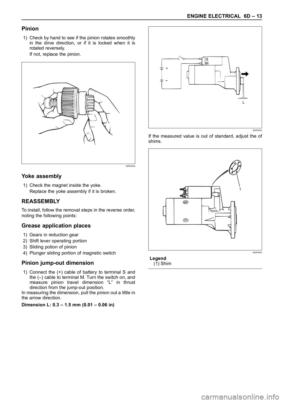
1) Check by hand to see if the pinion rotates smoothly
in the dirve direction, or if it is locked when it is
rotated reversely.
If not, replace the pinion.
Yoke assembly
1) Check the magnet inside the yoke.
Replace the yoke assembly if it is broken.
REASSEMBLY
To install, follow the removal steps in the reverse order,
noting the following points:
Grease application places
1) Gears in reduction gear
2) Shift lever operating portion
3) Sliding potion of pinion
4) Plunger sliding portion of magnetic switch
Pinion jump-out dimension
1) Connect the (+) cable of battery to terminal S and
the (–) cable to terminal M. Turn the switch on, and
measure pinion travel dimension “L” in thrust
direction from the jump-out position.
In measuring the dimension, pull the pinion out a little in
the arrow direction.
Dimension L: 0.3 – 1.5 mm (0.01 – 0.06 in)If the measured value is out of standard, adjust the of
shims.
Legend
(1) Shim
065RW048
S
+
L M
065RW054
1
065RW053
Page 5424 of 6000
ENGINE ELECTRICAL 6D – 21
Rectifier Assembly
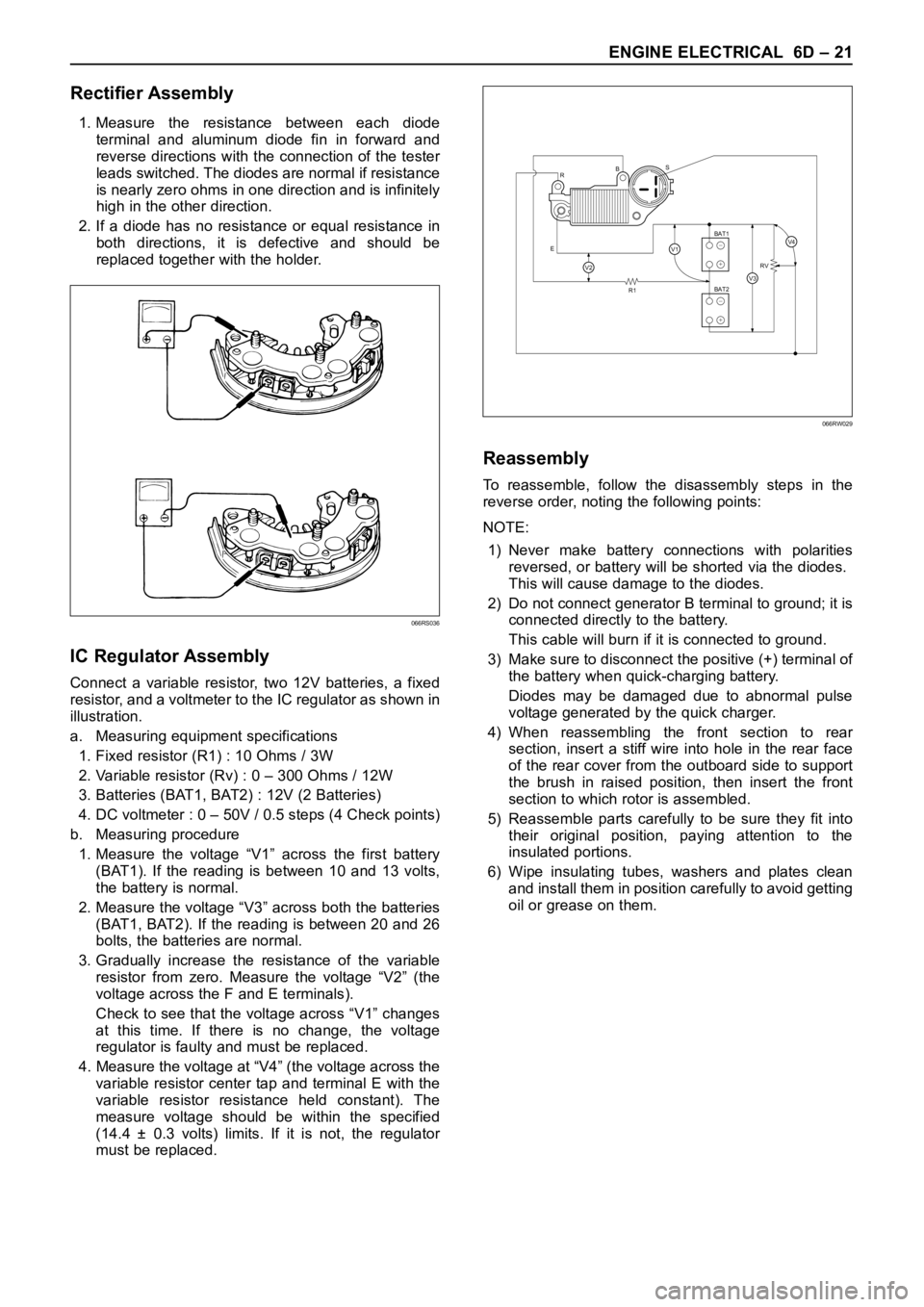
1. Measure the resistance between each diode
terminal and aluminum diode fin in forward and
reverse directions with the connection of the tester
leads switched. The diodes are normal if resistance
is nearly zero ohms in one direction and is infinitely
high in the other direction.
2. If a diode has no resistance or equal resistance in
both directions, it is defective and should be
replaced together with the holder.
IC Regulator Assembly
Connect a variable resistor, two 12V batteries, a fixed
resistor, and a voltmeter to the IC regulator as shown in
illustration.
a. Measuring equipment specifications
1. Fixed resistor (R1) : 10 Ohms / 3W
2. Variable resistor (Rv) : 0 – 300 Ohms / 12W
3. Batteries (BAT1, BAT2) : 12V (2 Batteries)
4. DC voltmeter : 0 – 50V / 0.5 steps (4 Check points)
b. Measuring procedure
1. Measure the voltage “V1” across the first battery
(BAT1). If the reading is between 10 and 13 volts,
the battery is normal.
2. Measure the voltage “V3” across both the batteries
(BAT1, BAT2). If the reading is between 20 and 26
bolts, the batteries are normal.
3. Gradually increase the resistance of the variable
resistor from zero. Measure the voltage “V2” (the
voltage across the F and E terminals).
Check to see that the voltage across “V1” changes
at this time. If there is no change, the voltage
regulator is faulty and must be replaced.
4. Measure the voltage at “V4” (the voltage across the
variable resistor center tap and terminal E with the
variable resistor resistance held constant). The
measure voltage should be within the specified
(14.4 ± 0.3 volts) limits. If it is not, the regulator
must be replaced.
Reassembly
To reassemble, follow the disassembly steps in the
reverse order, noting the following points:
NOTE:
1) Never make battery connections with polarities
reversed, or battery will be shorted via the diodes.
This will cause damage to the diodes.
2) Do not connect generator B terminal to ground; it is
connected directly to the battery.
This cable will burn if it is connected to ground.
3) Make sure to disconnect the positive (+) terminal of
the battery when quick-charging battery.
Diodes may be damaged due to abnormal pulse
voltage generated by the quick charger.
4) When reassembling the front section to rear
section, insert a stiff wire into hole in the rear face
of the rear cover from the outboard side to support
the brush in raised position, then insert the front
section to which rotor is assembled.
5) Reassemble parts carefully to be sure they fit into
their original position, paying attention to the
insulated portions.
6) Wipe insulating tubes, washers and plates clean
and install them in position carefully to avoid getting
oil or grease on them.
066RS036
R
EBS
R1RV
BAT2 BAT1
V2V3
V4V1+
−
+
−
066RW029
Page 5425 of 6000
6D – 22 ENGINE ELECTRICAL
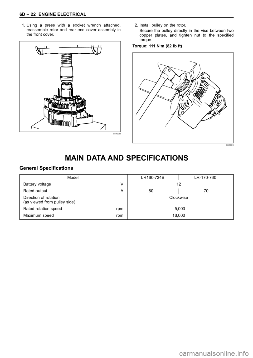
1. Using a press with a socket wrench attached,
reassemble rotor and rear end cover assembly in
the front cover.2. Install pulley on the rotor.
Secure the pulley directly in the vise between two
copper plates, and tighten nut to the specified
torque.
Torque: 111 Nꞏm (82 lb ft)
066RS022
066RS010
MAIN DATA AND SPECIFICATIONS
General Specifications
Model LR160-734B LR-170-760
Battery voltage V 12
Rated output A 60 70
Direction of rotation Clockwise
(as viewed from pulley side)
Rated rotation speed rpm 5,000
Maximum speed rpm 18,000
Page 5719 of 6000
7A–30
AUTOMATIC TRANSMISSION (4L30–E)
Removal
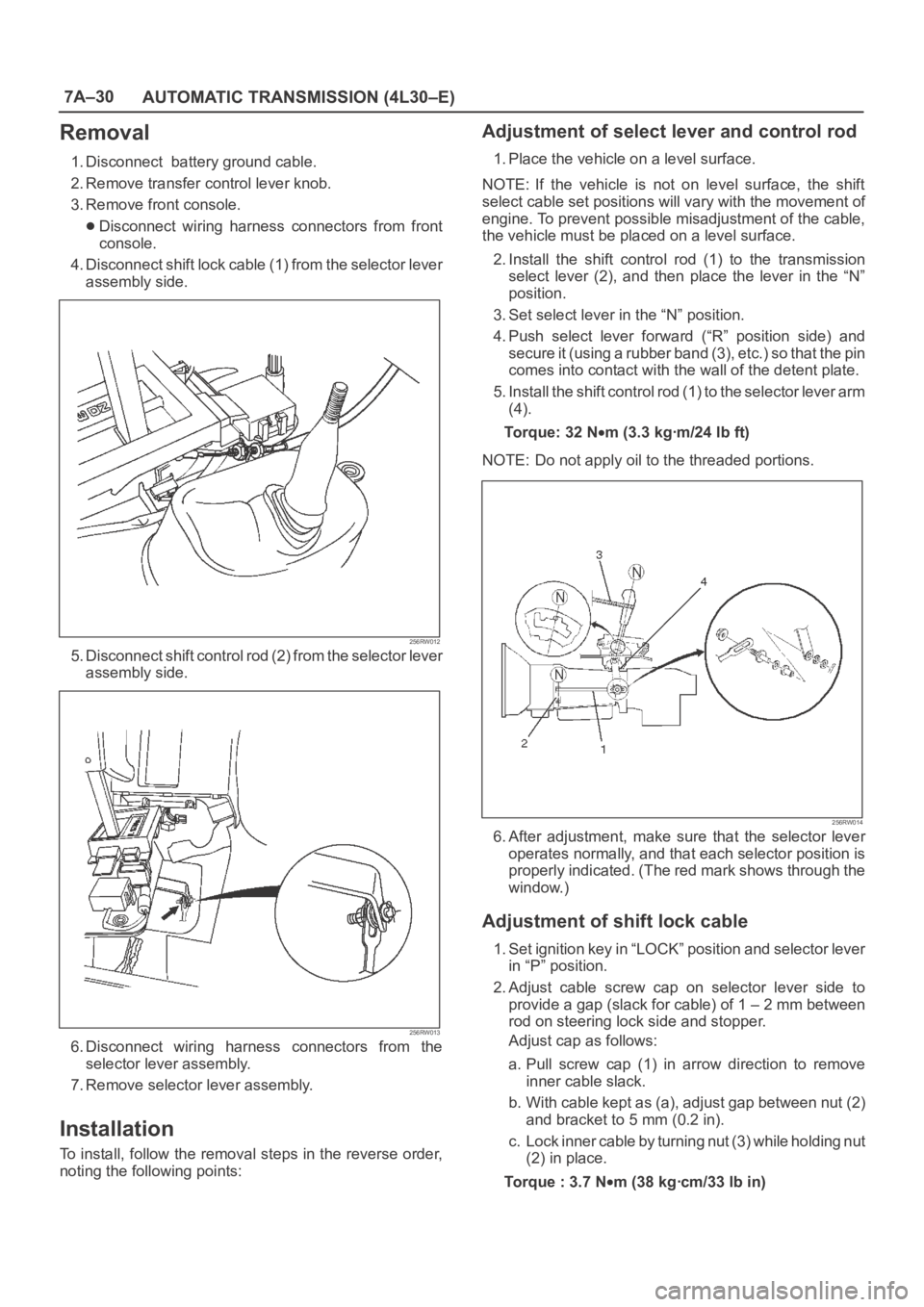
1. Disconnect battery ground cable.
2. Remove transfer control lever knob.
3. Remove front console.
Disconnect wiring harness connectors from front
console.
4. Disconnect shift lock cable (1) from the selector lever
assembly side.
256RW012
5. Disconnect shift control rod (2) from the selector lever
assembly side.
256RW013
6. Disconnect wiring harness connectors from the
selector lever assembly.
7. Remove selector lever assembly.
Installation
To install, follow the removal steps in the reverse order,
noting the following points:
Adjustment of select lever and control rod
1. Place the vehicle on a level surface.
NOTE: If the vehicle is not on level surface, the shift
select cable set positions will vary with the movement of
engine. To prevent possible misadjustment of the cable,
the vehicle must be placed on a level surface.
2. Install the shift control rod (1) to the transmission
select lever (2), and then place the lever in the “N”
position.
3. Set select lever in the “N” position.
4. Push select lever forward (“R” position side) and
s e c u r e i t ( u s i n g a r u b b e r b a n d ( 3 ) , e t c . ) s o t h a t t h e p i n
comes into contact with the wall of the detent plate.
5. Install the shift control rod (1) to the selector lever arm
(4).
To r q u e : 3 2 N
m (3.3 kgꞏm/24 lb ft)
NOTE: Do not apply oil to the threaded portions.
256RW014
6. After adjustment, make sure that the selector lever
operates normally, and that each selector position is
properly indicated. (The red mark shows through the
window.)
Adjustment of shift lock cable
1. Set ignition key in “LOCK” position and selector lever
in “P” position.
2. Adjust cable screw cap on selector lever side to
provide a gap (slack for cable) of 1 – 2 mm between
rod on steering lock side and stopper.
Adjust cap as follows:
a. Pull screw cap (1) in arrow direction to remove
inner cable slack.
b. With cable kept as (a), adjust gap between nut (2)
and bracket to 5 mm (0.2 in).
c. Lock inner cable by turning nut (3) while holding nut
(2) in place.
Torque : 3.7 N
m (38 kgꞏcm/33 lb in)
Page 5721 of 6000
7A–32
AUTOMATIC TRANSMISSION (4L30–E)
h. Reinstall the selector lever.
249RW001
Procedure 2
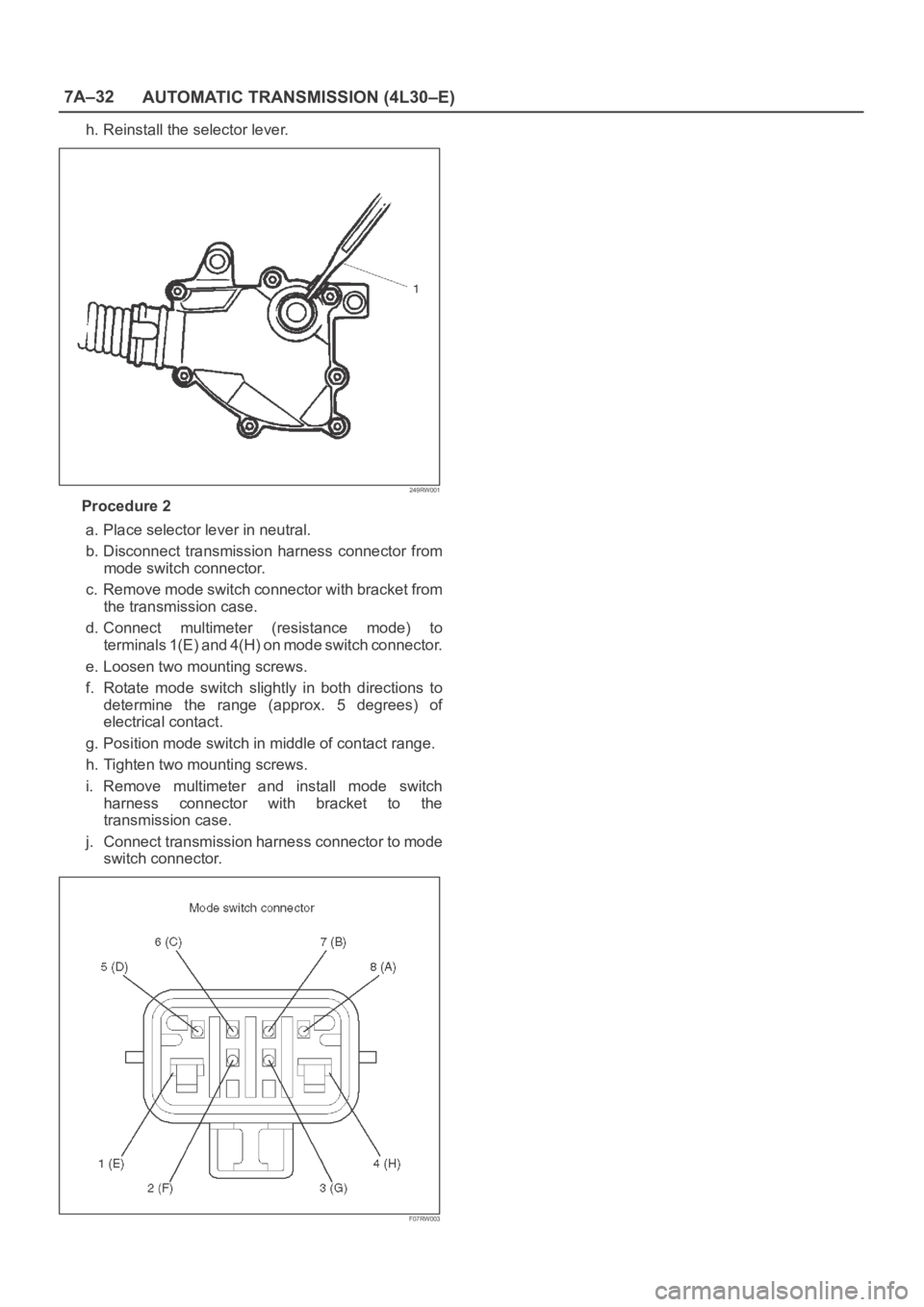
a. Place selector lever in neutral.
b. Disconnect transmission harness connector from
mode switch connector.
c. Remove mode switch connector with bracket from
the transmission case.
d. Connect multimeter (resistance mode) to
terminals 1(E) and 4(H) on mode switch connector.
e. Loosen two mounting screws.
f. Rotate mode switch slightly in both directions to
determine the range (approx. 5 degrees) of
electrical contact.
g. Position mode switch in middle of contact range.
h. Tighten two mounting screws.
i. Remove multimeter and install mode switch
harness connector with bracket to the
transmission case.
j. Connect transmission harness connector to mode
switch connector.
F07RW003
Page 5767 of 6000
7A–78
AUTOMATIC TRANSMISSION (4L30–E)
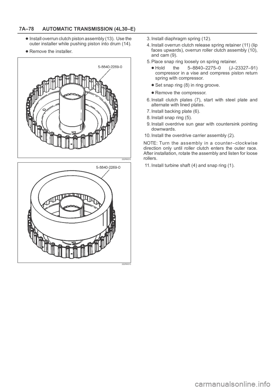
Install overrun clutch piston assembly (13). Use the
outer installer while pushing piston into drum (14).
Remove the installer.
252RW012
252RW013
3. Install diaphragm spring (12).
4. Install overrun clutch release spring retainer (11) (lip
faces upwards), overrun roller clutch assembly (10),
and cam (9).
5. Place snap ring loosely on spring retainer.
Hold the 5–8840–2275–0 (J–23327–91)
compressor in a vise and compress piston return
spring with compressor.
Set snap ring (8) in ring groove.
Remove the compressor.
6. Install clutch plates (7), start with steel plate and
alternate with lined plates.
7. Install backing plate (6).
8. Install snap ring (5).
9. Install overdrive sun gear with countersink pointing
downwards.
10. Install the overdrive carrier assembly (2).
NOTE: Tu r n t h e a s s e m b l y i n a c o u n t e r – c l o c k w i s e
direction only until roller clutch enters the outer race.
After installation, rotate the assembly and listen for loose
rollers.
11. Install turbine shaft (4) and snap ring (1).
Page 5862 of 6000
AUTOMATIC TRANSMISSION (AW30-40LE) 7A–81
256RW014
256RW015
INSTALLATION
To install, follow the removal steps in the reverse order, noting
the following points;
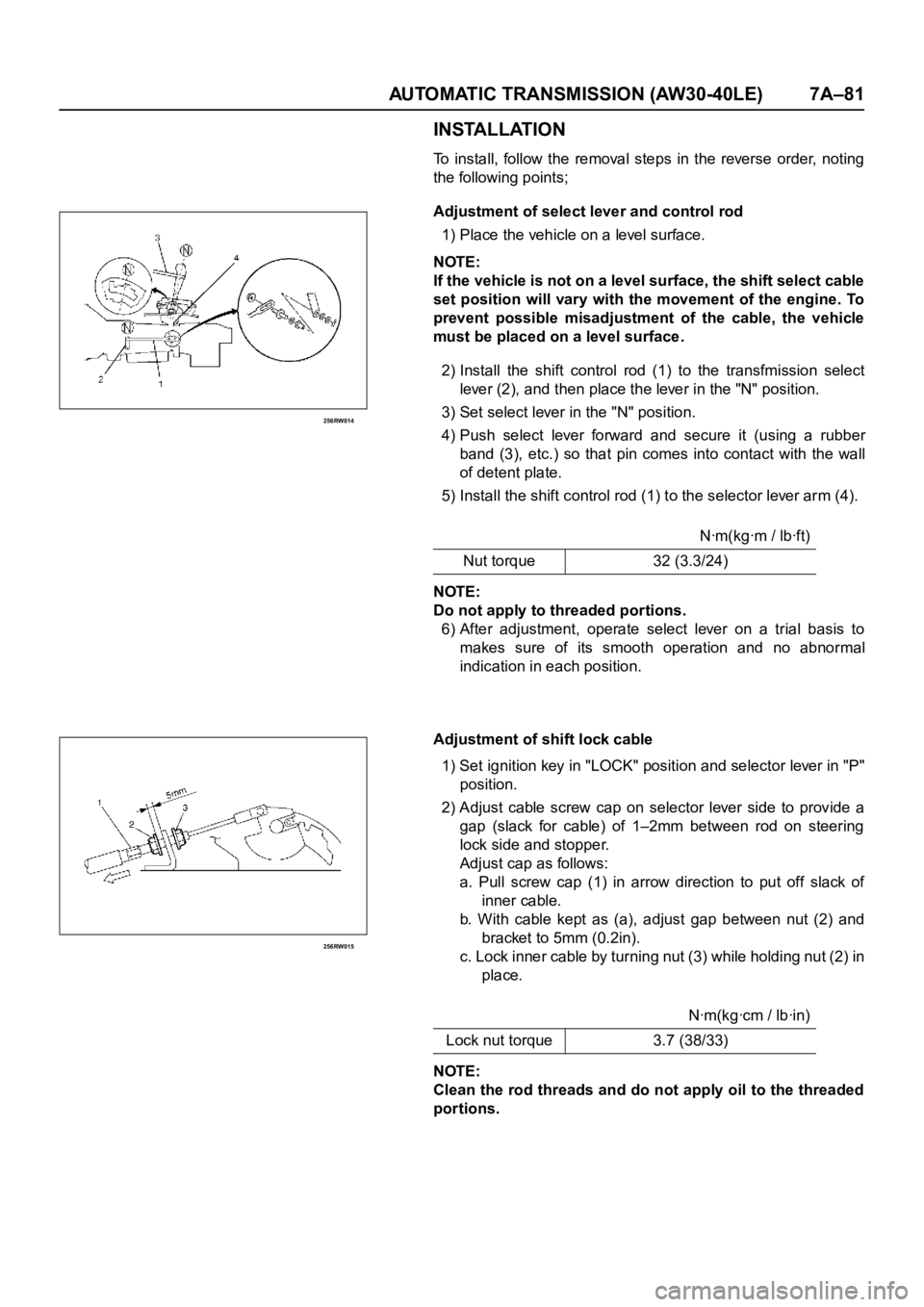
Adjustment of select lever and control rod
1) Place the vehicle on a level surface.
NOTE:
If the vehicle is not on a level surface, the shift select cable
set position will vary with the movement of the engine. To
prevent possible misadjustment of the cable, the vehicle
must be placed on a level surface.
2) Install the shift control rod (1) to the transfmission select
lever (2), and then place the lever in the "N" position.
3) Set select lever in the "N" position.
4) Push select lever forward and secure it (using a rubber
band (3), etc.) so that pin comes into contact with the wall
of detent plate.
5) Install the shift control rod (1) to the selector lever arm (4).
NOTE:
Do not apply to threaded portions.
6) After adjustment, operate select lever on a trial basis to
makes sure of its smooth operation and no abnormal
indication in each position.
Adjustment of shift lock cable
1) Set ignition key in "LOCK" position and selector lever in "P"
position.
2) Adjust cable screw cap on selector lever side to provide a
gap (slack for cable) of 1–2mm between rod on steering
lock side and stopper.
Adjust cap as follows:
a. Pull screw cap (1) in arrow direction to put off slack of
inner cable.
b. With cable kept as (a), adjust gap between nut (2) and
bracket to 5mm (0.2in).
c. Lock inner cable by tur ning nut (3) while holding nut (2) in
place.
NOTE:
Clean the rod threads and do not apply oil to the threaded
portions.Nꞏm(kgꞏm / lbꞏft)
Nut torque 32 (3.3/24)
Nꞏm(kgꞏcm / lbꞏin)
Lock nut torque 3.7 (38/33)
Page 5950 of 6000
AUTOMATIC TRANSMISSION (AW30-40LE) 7A–169
246RY00013
247RY00047
247RY00028
247RY00042
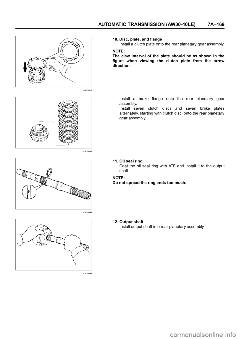
10. Disc, plate, and flange
Install a clutch plate onto the rear planetary gear assembly.
NOTE:
The claw interval of the plate should be as shown in the
figure when viewing the clutch plate from the arrow
direction.
Install a brake flange onto the rear planetary gear
assembly.
Install seven clutch discs and seven brake plates
alternately, star ting with clutch disc, onto the rear planetary
gear assembly.
11. Oil seal ring
Coat the oil seal ring with ATF and install it to the output
shaft.
NOTE:
Do not spread the ring ends too much.
12. Output shaft
Install output shaft into rear planetary assembly.