1998 OPEL FRONTERA coolant
[x] Cancel search: coolantPage 1895 of 6000
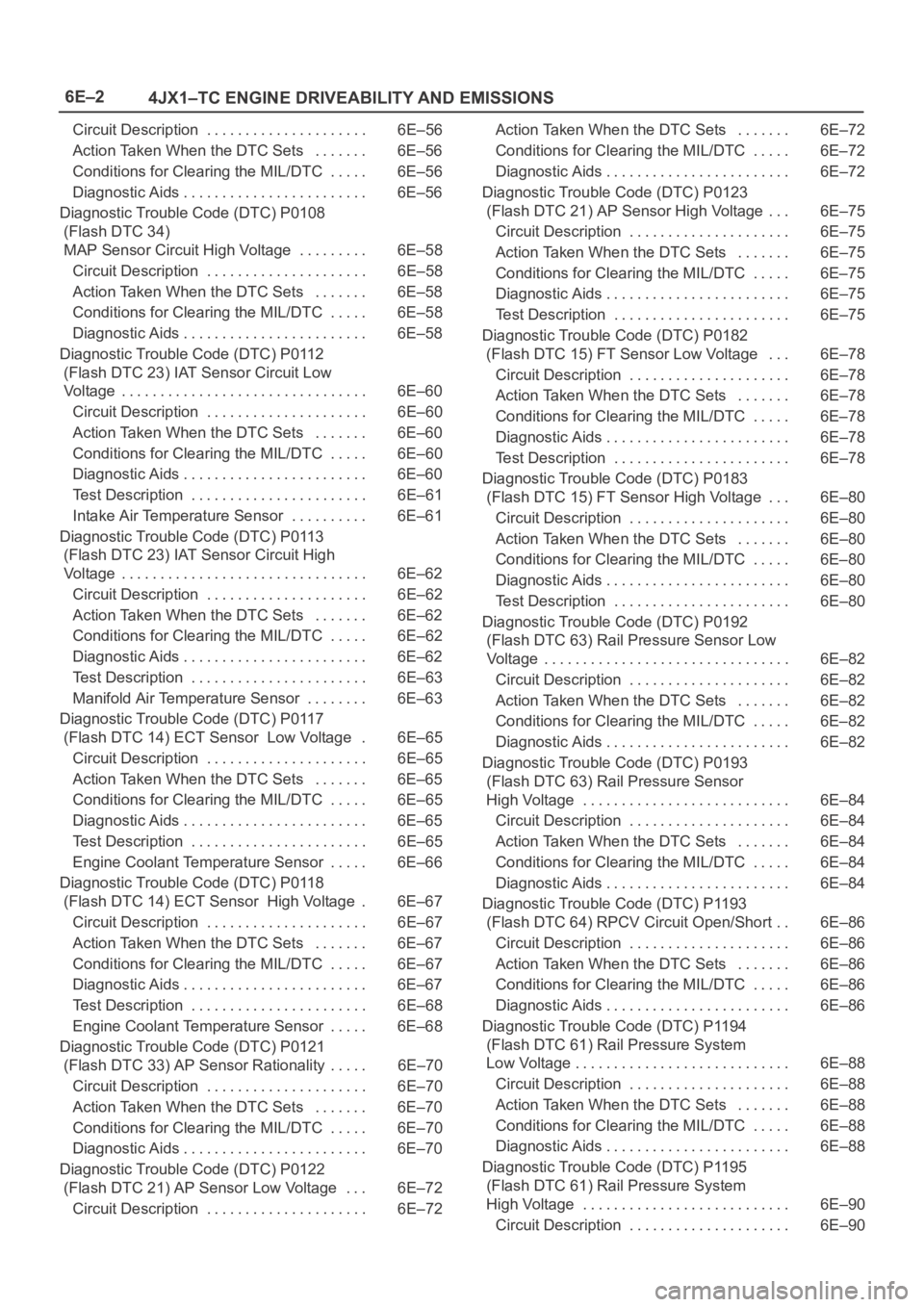
6E–2
4JX1–TC ENGINE DRIVEABILITY AND EMISSIONS
Circuit Description 6E–56. . . . . . . . . . . . . . . . . . . . .
Action Taken When the DTC Sets 6E–56. . . . . . .
Conditions for Clearing the MIL/DTC 6E–56. . . . .
Diagnostic Aids 6E–56. . . . . . . . . . . . . . . . . . . . . . . .
Diagnostic Trouble Code (DTC) P0108
(Flash DTC 34)
MAP Sensor Circuit High Voltage 6E–58. . . . . . . . .
Circuit Description 6E–58. . . . . . . . . . . . . . . . . . . . .
Action Taken When the DTC Sets 6E–58. . . . . . .
Conditions for Clearing the MIL/DTC 6E–58. . . . .
Diagnostic Aids 6E–58. . . . . . . . . . . . . . . . . . . . . . . .
Diagnostic Trouble Code (DTC) P0112
(Flash DTC 23) IAT Sensor Circuit Low
Voltage 6E–60. . . . . . . . . . . . . . . . . . . . . . . . . . . . . . . .
Circuit Description 6E–60. . . . . . . . . . . . . . . . . . . . .
Action Taken When the DTC Sets 6E–60. . . . . . .
Conditions for Clearing the MIL/DTC 6E–60. . . . .
Diagnostic Aids 6E–60. . . . . . . . . . . . . . . . . . . . . . . .
Test Description 6E–61. . . . . . . . . . . . . . . . . . . . . . .
Intake Air Temperature Sensor 6E–61. . . . . . . . . .
Diagnostic Trouble Code (DTC) P0113
(Flash DTC 23) IAT Sensor Circuit High
Voltage 6E–62. . . . . . . . . . . . . . . . . . . . . . . . . . . . . . . .
Circuit Description 6E–62. . . . . . . . . . . . . . . . . . . . .
Action Taken When the DTC Sets 6E–62. . . . . . .
Conditions for Clearing the MIL/DTC 6E–62. . . . .
Diagnostic Aids 6E–62. . . . . . . . . . . . . . . . . . . . . . . .
Test Description 6E–63. . . . . . . . . . . . . . . . . . . . . . .
Manifold Air Temperature Sensor 6E–63. . . . . . . .
Diagnostic Trouble Code (DTC) P0117
(Flash DTC 14) ECT Sensor Low Voltage 6E–65.
Circuit Description 6E–65. . . . . . . . . . . . . . . . . . . . .
Action Taken When the DTC Sets 6E–65. . . . . . .
Conditions for Clearing the MIL/DTC 6E–65. . . . .
Diagnostic Aids 6E–65. . . . . . . . . . . . . . . . . . . . . . . .
Test Description 6E–65. . . . . . . . . . . . . . . . . . . . . . .
Engine Coolant Temperature Sensor 6E–66. . . . .
Diagnostic Trouble Code (DTC) P0118
(Flash DTC 14) ECT Sensor High Voltage 6E–67.
Circuit Description 6E–67. . . . . . . . . . . . . . . . . . . . .
Action Taken When the DTC Sets 6E–67. . . . . . .
Conditions for Clearing the MIL/DTC 6E–67. . . . .
Diagnostic Aids 6E–67. . . . . . . . . . . . . . . . . . . . . . . .
Test Description 6E–68. . . . . . . . . . . . . . . . . . . . . . .
Engine Coolant Temperature Sensor 6E–68. . . . .
Diagnostic Trouble Code (DTC) P0121
(Flash DTC 33) AP Sensor Rationality 6E–70. . . . .
Circuit Description 6E–70. . . . . . . . . . . . . . . . . . . . .
Action Taken When the DTC Sets 6E–70. . . . . . .
Conditions for Clearing the MIL/DTC 6E–70. . . . .
Diagnostic Aids 6E–70. . . . . . . . . . . . . . . . . . . . . . . .
Diagnostic Trouble Code (DTC) P0122
(Flash DTC 21) AP Sensor Low Voltage 6E–72. . .
Circuit Description 6E–72. . . . . . . . . . . . . . . . . . . . . Action Taken When the DTC Sets 6E–72. . . . . . .
Conditions for Clearing the MIL/DTC 6E–72. . . . .
Diagnostic Aids 6E–72. . . . . . . . . . . . . . . . . . . . . . . .
Diagnostic Trouble Code (DTC) P0123
(Flash DTC 21) AP Sensor High Voltage 6E–75. . .
Circuit Description 6E–75. . . . . . . . . . . . . . . . . . . . .
Action Taken When the DTC Sets 6E–75. . . . . . .
Conditions for Clearing the MIL/DTC 6E–75. . . . .
Diagnostic Aids 6E–75. . . . . . . . . . . . . . . . . . . . . . . .
Test Description 6E–75. . . . . . . . . . . . . . . . . . . . . . .
Diagnostic Trouble Code (DTC) P0182
(Flash DTC 15) FT Sensor Low Voltage 6E–78. . .
Circuit Description 6E–78. . . . . . . . . . . . . . . . . . . . .
Action Taken When the DTC Sets 6E–78. . . . . . .
Conditions for Clearing the MIL/DTC 6E–78. . . . .
Diagnostic Aids 6E–78. . . . . . . . . . . . . . . . . . . . . . . .
Test Description 6E–78. . . . . . . . . . . . . . . . . . . . . . .
Diagnostic Trouble Code (DTC) P0183
(Flash DTC 15) FT Sensor High Voltage 6E–80. . .
Circuit Description 6E–80. . . . . . . . . . . . . . . . . . . . .
Action Taken When the DTC Sets 6E–80. . . . . . .
Conditions for Clearing the MIL/DTC 6E–80. . . . .
Diagnostic Aids 6E–80. . . . . . . . . . . . . . . . . . . . . . . .
Test Description 6E–80. . . . . . . . . . . . . . . . . . . . . . .
Diagnostic Trouble Code (DTC) P0192
(Flash DTC 63) Rail Pressure Sensor Low
Voltage 6E–82. . . . . . . . . . . . . . . . . . . . . . . . . . . . . . . .
Circuit Description 6E–82. . . . . . . . . . . . . . . . . . . . .
Action Taken When the DTC Sets 6E–82. . . . . . .
Conditions for Clearing the MIL/DTC 6E–82. . . . .
Diagnostic Aids 6E–82. . . . . . . . . . . . . . . . . . . . . . . .
Diagnostic Trouble Code (DTC) P0193
(Flash DTC 63) Rail Pressure Sensor
High Voltage 6E–84. . . . . . . . . . . . . . . . . . . . . . . . . . .
Circuit Description 6E–84. . . . . . . . . . . . . . . . . . . . .
Action Taken When the DTC Sets 6E–84. . . . . . .
Conditions for Clearing the MIL/DTC 6E–84. . . . .
Diagnostic Aids 6E–84. . . . . . . . . . . . . . . . . . . . . . . .
Diagnostic Trouble Code (DTC) P1193
(Flash DTC 64) RPCV Circuit Open/Short 6E–86. .
Circuit Description 6E–86. . . . . . . . . . . . . . . . . . . . .
Action Taken When the DTC Sets 6E–86. . . . . . .
Conditions for Clearing the MIL/DTC 6E–86. . . . .
Diagnostic Aids 6E–86. . . . . . . . . . . . . . . . . . . . . . . .
Diagnostic Trouble Code (DTC) P1194
(Flash DTC 61) Rail Pressure System
Low Voltage 6E–88. . . . . . . . . . . . . . . . . . . . . . . . . . . .
Circuit Description 6E–88. . . . . . . . . . . . . . . . . . . . .
Action Taken When the DTC Sets 6E–88. . . . . . .
Conditions for Clearing the MIL/DTC 6E–88. . . . .
Diagnostic Aids 6E–88. . . . . . . . . . . . . . . . . . . . . . . .
Diagnostic Trouble Code (DTC) P1195
(Flash DTC 61) Rail Pressure System
High Voltage 6E–90. . . . . . . . . . . . . . . . . . . . . . . . . . .
Circuit Description 6E–90. . . . . . . . . . . . . . . . . . . . .
Page 1896 of 6000
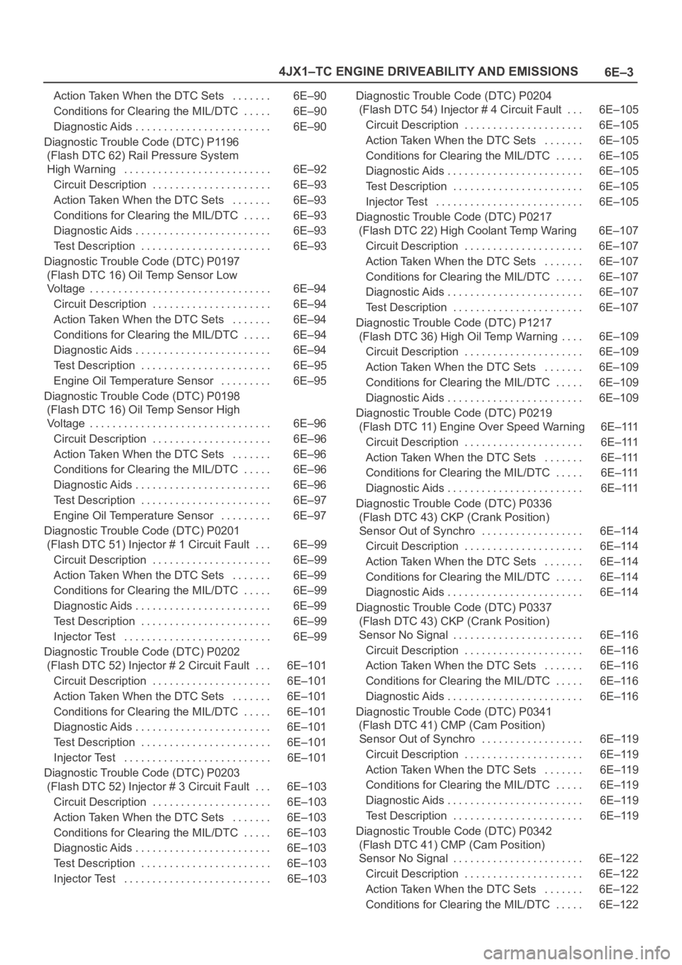
6E–3 4JX1–TC ENGINE DRIVEABILITY AND EMISSIONS
Action Taken When the DTC Sets 6E–90. . . . . . .
Conditions for Clearing the MIL/DTC 6E–90. . . . .
Diagnostic Aids 6E–90. . . . . . . . . . . . . . . . . . . . . . . .
Diagnostic Trouble Code (DTC) P1196
(Flash DTC 62) Rail Pressure System
High Warning 6E–92. . . . . . . . . . . . . . . . . . . . . . . . . .
Circuit Description 6E–93. . . . . . . . . . . . . . . . . . . . .
Action Taken When the DTC Sets 6E–93. . . . . . .
Conditions for Clearing the MIL/DTC 6E–93. . . . .
Diagnostic Aids 6E–93. . . . . . . . . . . . . . . . . . . . . . . .
Test Description 6E–93. . . . . . . . . . . . . . . . . . . . . . .
Diagnostic Trouble Code (DTC) P0197
(Flash DTC 16) Oil Temp Sensor Low
Voltage 6E–94. . . . . . . . . . . . . . . . . . . . . . . . . . . . . . . .
Circuit Description 6E–94. . . . . . . . . . . . . . . . . . . . .
Action Taken When the DTC Sets 6E–94. . . . . . .
Conditions for Clearing the MIL/DTC 6E–94. . . . .
Diagnostic Aids 6E–94. . . . . . . . . . . . . . . . . . . . . . . .
Test Description 6E–95. . . . . . . . . . . . . . . . . . . . . . .
Engine Oil Temperature Sensor 6E–95. . . . . . . . .
Diagnostic Trouble Code (DTC) P0198
(Flash DTC 16) Oil Temp Sensor High
Voltage 6E–96. . . . . . . . . . . . . . . . . . . . . . . . . . . . . . . .
Circuit Description 6E–96. . . . . . . . . . . . . . . . . . . . .
Action Taken When the DTC Sets 6E–96. . . . . . .
Conditions for Clearing the MIL/DTC 6E–96. . . . .
Diagnostic Aids 6E–96. . . . . . . . . . . . . . . . . . . . . . . .
Test Description 6E–97. . . . . . . . . . . . . . . . . . . . . . .
Engine Oil Temperature Sensor 6E–97. . . . . . . . .
Diagnostic Trouble Code (DTC) P0201
(Flash DTC 51) Injector # 1 Circuit Fault 6E–99. . .
Circuit Description 6E–99. . . . . . . . . . . . . . . . . . . . .
Action Taken When the DTC Sets 6E–99. . . . . . .
Conditions for Clearing the MIL/DTC 6E–99. . . . .
Diagnostic Aids 6E–99. . . . . . . . . . . . . . . . . . . . . . . .
Test Description 6E–99. . . . . . . . . . . . . . . . . . . . . . .
Injector Test 6E–99. . . . . . . . . . . . . . . . . . . . . . . . . .
Diagnostic Trouble Code (DTC) P0202
(Flash DTC 52) Injector # 2 Circuit Fault 6E–101. . .
Circuit Description 6E–101. . . . . . . . . . . . . . . . . . . . .
Action Taken When the DTC Sets 6E–101. . . . . . .
Conditions for Clearing the MIL/DTC 6E–101. . . . .
Diagnostic Aids 6E–101. . . . . . . . . . . . . . . . . . . . . . . .
Test Description 6E–101. . . . . . . . . . . . . . . . . . . . . . .
Injector Test 6E–101. . . . . . . . . . . . . . . . . . . . . . . . . .
Diagnostic Trouble Code (DTC) P0203
(Flash DTC 52) Injector # 3 Circuit Fault 6E–103. . .
Circuit Description 6E–103. . . . . . . . . . . . . . . . . . . . .
Action Taken When the DTC Sets 6E–103. . . . . . .
Conditions for Clearing the MIL/DTC 6E–103. . . . .
Diagnostic Aids 6E–103. . . . . . . . . . . . . . . . . . . . . . . .
Test Description 6E–103. . . . . . . . . . . . . . . . . . . . . . .
Injector Test 6E–103. . . . . . . . . . . . . . . . . . . . . . . . . . Diagnostic Trouble Code (DTC) P0204
(Flash DTC 54) Injector # 4 Circuit Fault 6E–105
. . .
Circuit Description 6E–105. . . . . . . . . . . . . . . . . . . . .
Action Taken When the DTC Sets 6E–105. . . . . . .
Conditions for Clearing the MIL/DTC 6E–105. . . . .
Diagnostic Aids 6E–105. . . . . . . . . . . . . . . . . . . . . . . .
Test Description 6E–105. . . . . . . . . . . . . . . . . . . . . . .
Injector Test 6E–105. . . . . . . . . . . . . . . . . . . . . . . . . .
Diagnostic Trouble Code (DTC) P0217
(Flash DTC 22) High Coolant Temp Waring 6E–107
Circuit Description 6E–107. . . . . . . . . . . . . . . . . . . . .
Action Taken When the DTC Sets 6E–107. . . . . . .
Conditions for Clearing the MIL/DTC 6E–107. . . . .
Diagnostic Aids 6E–107. . . . . . . . . . . . . . . . . . . . . . . .
Test Description 6E–107. . . . . . . . . . . . . . . . . . . . . . .
Diagnostic Trouble Code (DTC) P1217
(Flash DTC 36) High Oil Temp Warning 6E–109. . . .
Circuit Description 6E–109. . . . . . . . . . . . . . . . . . . . .
Action Taken When the DTC Sets 6E–109. . . . . . .
Conditions for Clearing the MIL/DTC 6E–109. . . . .
Diagnostic Aids 6E–109. . . . . . . . . . . . . . . . . . . . . . . .
Diagnostic Trouble Code (DTC) P0219
(Flash DTC 11) Engine Over Speed Warning 6E–111
Circuit Description 6E–111. . . . . . . . . . . . . . . . . . . . .
Action Taken When the DTC Sets 6E–111. . . . . . .
Conditions for Clearing the MIL/DTC 6E–111. . . . .
Diagnostic Aids 6E–111. . . . . . . . . . . . . . . . . . . . . . . .
Diagnostic Trouble Code (DTC) P0336
(Flash DTC 43) CKP (Crank Position)
Sensor Out of Synchro 6E–114. . . . . . . . . . . . . . . . . .
Circuit Description 6E–114. . . . . . . . . . . . . . . . . . . . .
Action Taken When the DTC Sets 6E–114. . . . . . .
Conditions for Clearing the MIL/DTC 6E–114. . . . .
Diagnostic Aids 6E–114. . . . . . . . . . . . . . . . . . . . . . . .
Diagnostic Trouble Code (DTC) P0337
(Flash DTC 43) CKP (Crank Position)
Sensor No Signal 6E–116. . . . . . . . . . . . . . . . . . . . . . .
Circuit Description 6E–116. . . . . . . . . . . . . . . . . . . . .
Action Taken When the DTC Sets 6E–116. . . . . . .
Conditions for Clearing the MIL/DTC 6E–116. . . . .
Diagnostic Aids 6E–116. . . . . . . . . . . . . . . . . . . . . . . .
Diagnostic Trouble Code (DTC) P0341
(Flash DTC 41) CMP (Cam Position)
Sensor Out of Synchro 6E–119. . . . . . . . . . . . . . . . . .
Circuit Description 6E–119. . . . . . . . . . . . . . . . . . . . .
Action Taken When the DTC Sets 6E–119. . . . . . .
Conditions for Clearing the MIL/DTC 6E–119. . . . .
Diagnostic Aids 6E–119. . . . . . . . . . . . . . . . . . . . . . . .
Test Description 6E–119. . . . . . . . . . . . . . . . . . . . . . .
Diagnostic Trouble Code (DTC) P0342
(Flash DTC 41) CMP (Cam Position)
Sensor No Signal 6E–122. . . . . . . . . . . . . . . . . . . . . . .
Circuit Description 6E–122. . . . . . . . . . . . . . . . . . . . .
Action Taken When the DTC Sets 6E–122. . . . . . .
Conditions for Clearing the MIL/DTC 6E–122. . . . .
Page 1898 of 6000
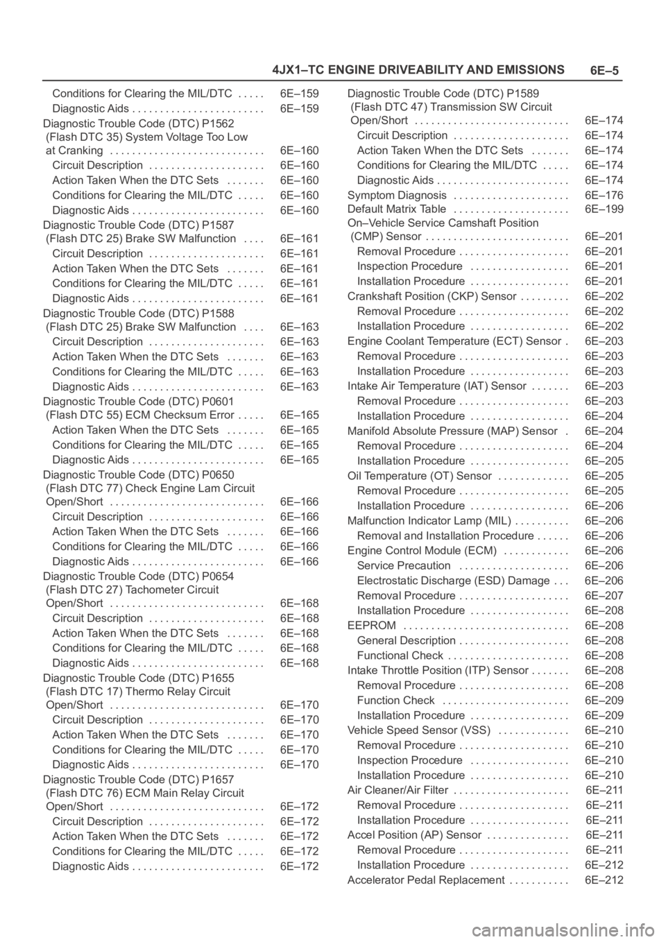
6E–5 4JX1–TC ENGINE DRIVEABILITY AND EMISSIONS
Conditions for Clearing the MIL/DTC 6E–159. . . . .
Diagnostic Aids 6E–159. . . . . . . . . . . . . . . . . . . . . . . .
Diagnostic Trouble Code (DTC) P1562
(Flash DTC 35) System Voltage Too Low
at Cranking 6E–160. . . . . . . . . . . . . . . . . . . . . . . . . . . .
Circuit Description 6E–160. . . . . . . . . . . . . . . . . . . . .
Action Taken When the DTC Sets 6E–160. . . . . . .
Conditions for Clearing the MIL/DTC 6E–160. . . . .
Diagnostic Aids 6E–160. . . . . . . . . . . . . . . . . . . . . . . .
Diagnostic Trouble Code (DTC) P1587
(Flash DTC 25) Brake SW Malfunction 6E–161. . . .
Circuit Description 6E–161. . . . . . . . . . . . . . . . . . . . .
Action Taken When the DTC Sets 6E–161. . . . . . .
Conditions for Clearing the MIL/DTC 6E–161. . . . .
Diagnostic Aids 6E–161. . . . . . . . . . . . . . . . . . . . . . . .
Diagnostic Trouble Code (DTC) P1588
(Flash DTC 25) Brake SW Malfunction 6E–163. . . .
Circuit Description 6E–163. . . . . . . . . . . . . . . . . . . . .
Action Taken When the DTC Sets 6E–163. . . . . . .
Conditions for Clearing the MIL/DTC 6E–163. . . . .
Diagnostic Aids 6E–163. . . . . . . . . . . . . . . . . . . . . . . .
Diagnostic Trouble Code (DTC) P0601
(Flash DTC 55) ECM Checksum Error 6E–165. . . . .
Action Taken When the DTC Sets 6E–165. . . . . . .
Conditions for Clearing the MIL/DTC 6E–165. . . . .
Diagnostic Aids 6E–165. . . . . . . . . . . . . . . . . . . . . . . .
Diagnostic Trouble Code (DTC) P0650
(Flash DTC 77) Check Engine Lam Circuit
Open/Short 6E–166. . . . . . . . . . . . . . . . . . . . . . . . . . . .
Circuit Description 6E–166. . . . . . . . . . . . . . . . . . . . .
Action Taken When the DTC Sets 6E–166. . . . . . .
Conditions for Clearing the MIL/DTC 6E–166. . . . .
Diagnostic Aids 6E–166. . . . . . . . . . . . . . . . . . . . . . . .
Diagnostic Trouble Code (DTC) P0654
(Flash DTC 27) Tachometer Circuit
Open/Short 6E–168. . . . . . . . . . . . . . . . . . . . . . . . . . . .
Circuit Description 6E–168. . . . . . . . . . . . . . . . . . . . .
Action Taken When the DTC Sets 6E–168. . . . . . .
Conditions for Clearing the MIL/DTC 6E–168. . . . .
Diagnostic Aids 6E–168. . . . . . . . . . . . . . . . . . . . . . . .
Diagnostic Trouble Code (DTC) P1655
(Flash DTC 17) Thermo Relay Circuit
Open/Short 6E–170. . . . . . . . . . . . . . . . . . . . . . . . . . . .
Circuit Description 6E–170. . . . . . . . . . . . . . . . . . . . .
Action Taken When the DTC Sets 6E–170. . . . . . .
Conditions for Clearing the MIL/DTC 6E–170. . . . .
Diagnostic Aids 6E–170. . . . . . . . . . . . . . . . . . . . . . . .
Diagnostic Trouble Code (DTC) P1657
(Flash DTC 76) ECM Main Relay Circuit
Open/Short 6E–172. . . . . . . . . . . . . . . . . . . . . . . . . . . .
Circuit Description 6E–172. . . . . . . . . . . . . . . . . . . . .
Action Taken When the DTC Sets 6E–172. . . . . . .
Conditions for Clearing the MIL/DTC 6E–172. . . . .
Diagnostic Aids 6E–172. . . . . . . . . . . . . . . . . . . . . . . . Diagnostic Trouble Code (DTC) P1589
(Flash DTC 47) Transmission SW Circuit
Open/Short 6E–174. . . . . . . . . . . . . . . . . . . . . . . . . . . .
Circuit Description 6E–174. . . . . . . . . . . . . . . . . . . . .
Action Taken When the DTC Sets 6E–174. . . . . . .
Conditions for Clearing the MIL/DTC 6E–174. . . . .
Diagnostic Aids 6E–174. . . . . . . . . . . . . . . . . . . . . . . .
Symptom Diagnosis 6E–176. . . . . . . . . . . . . . . . . . . . .
Default Matrix Table 6E–199. . . . . . . . . . . . . . . . . . . . .
On–Vehicle Service Camshaft Position
(CMP) Sensor 6E–201. . . . . . . . . . . . . . . . . . . . . . . . . .
Removal Procedure 6E–201. . . . . . . . . . . . . . . . . . . .
Inspection Procedure 6E–201. . . . . . . . . . . . . . . . . .
Installation Procedure 6E–201. . . . . . . . . . . . . . . . . .
Crankshaft Position (CKP) Sensor 6E–202. . . . . . . . .
Removal Procedure 6E–202. . . . . . . . . . . . . . . . . . . .
Installation Procedure 6E–202. . . . . . . . . . . . . . . . . .
Engine Coolant Temperature (ECT) Sensor 6E–203.
Removal Procedure 6E–203. . . . . . . . . . . . . . . . . . . .
Installation Procedure 6E–203. . . . . . . . . . . . . . . . . .
Intake Air Temperature (IAT) Sensor 6E–203. . . . . . .
Removal Procedure 6E–203. . . . . . . . . . . . . . . . . . . .
Installation Procedure 6E–204. . . . . . . . . . . . . . . . . .
Manifold Absolute Pressure (MAP) Sensor 6E–204.
Removal Procedure 6E–204. . . . . . . . . . . . . . . . . . . .
Installation Procedure 6E–205. . . . . . . . . . . . . . . . . .
Oil Temperature (OT) Sensor 6E–205. . . . . . . . . . . . .
Removal Procedure 6E–205. . . . . . . . . . . . . . . . . . . .
Installation Procedure 6E–206. . . . . . . . . . . . . . . . . .
Malfunction Indicator Lamp (MIL) 6E–206. . . . . . . . . .
Removal and Installation Procedure 6E–206. . . . . .
Engine Control Module (ECM) 6E–206. . . . . . . . . . . .
Service Precaution 6E–206. . . . . . . . . . . . . . . . . . . .
Electrostatic Discharge (ESD) Damage 6E–206. . .
Removal Procedure 6E–207. . . . . . . . . . . . . . . . . . . .
Installation Procedure 6E–208. . . . . . . . . . . . . . . . . .
EEPROM 6E–208. . . . . . . . . . . . . . . . . . . . . . . . . . . . . .
General Description 6E–208. . . . . . . . . . . . . . . . . . . .
Functional Check 6E–208. . . . . . . . . . . . . . . . . . . . . .
Intake Throttle Position (ITP) Sensor 6E–208. . . . . . .
Removal Procedure 6E–208. . . . . . . . . . . . . . . . . . . .
Function Check 6E–209. . . . . . . . . . . . . . . . . . . . . . .
Installation Procedure 6E–209. . . . . . . . . . . . . . . . . .
Vehicle Speed Sensor (VSS) 6E–210. . . . . . . . . . . . .
Removal Procedure 6E–210. . . . . . . . . . . . . . . . . . . .
Inspection Procedure 6E–210. . . . . . . . . . . . . . . . . .
Installation Procedure 6E–210. . . . . . . . . . . . . . . . . .
Air Cleaner/Air Filter 6E–211. . . . . . . . . . . . . . . . . . . . .
Removal Procedure 6E–211. . . . . . . . . . . . . . . . . . . .
Installation Procedure 6E–211. . . . . . . . . . . . . . . . . .
Accel Position (AP) Sensor 6E–211. . . . . . . . . . . . . . .
Removal Procedure 6E–211. . . . . . . . . . . . . . . . . . . .
Installation Procedure 6E–212. . . . . . . . . . . . . . . . . .
Accelerator Pedal Replacement 6E–212. . . . . . . . . . .
Page 1899 of 6000
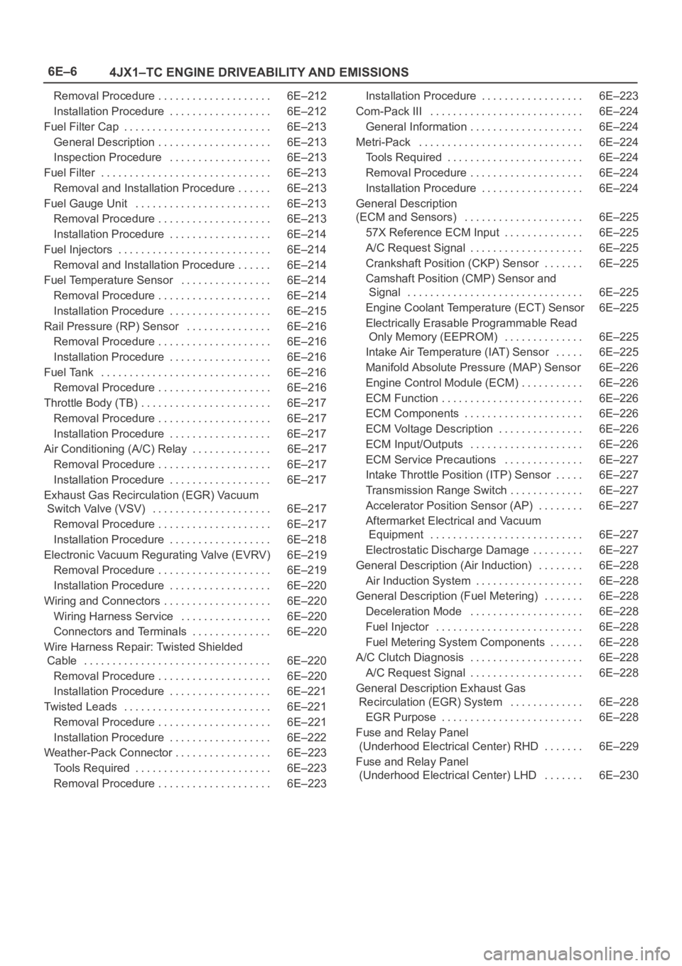
6E–6
4JX1–TC ENGINE DRIVEABILITY AND EMISSIONS
Removal Procedure 6E–212. . . . . . . . . . . . . . . . . . . .
Installation Procedure 6E–212. . . . . . . . . . . . . . . . . .
Fuel Filter Cap 6E–213. . . . . . . . . . . . . . . . . . . . . . . . . .
General Description 6E–213. . . . . . . . . . . . . . . . . . . .
Inspection Procedure 6E–213. . . . . . . . . . . . . . . . . .
Fuel Filter 6E–213. . . . . . . . . . . . . . . . . . . . . . . . . . . . . .
Removal and Installation Procedure 6E–213. . . . . .
Fuel Gauge Unit 6E–213. . . . . . . . . . . . . . . . . . . . . . . .
Removal Procedure 6E–213. . . . . . . . . . . . . . . . . . . .
Installation Procedure 6E–214. . . . . . . . . . . . . . . . . .
Fuel Injectors 6E–214. . . . . . . . . . . . . . . . . . . . . . . . . . .
Removal and Installation Procedure 6E–214. . . . . .
Fuel Temperature Sensor 6E–214. . . . . . . . . . . . . . . .
Removal Procedure 6E–214. . . . . . . . . . . . . . . . . . . .
Installation Procedure 6E–215. . . . . . . . . . . . . . . . . .
Rail Pressure (RP) Sensor 6E–216. . . . . . . . . . . . . . .
Removal Procedure 6E–216. . . . . . . . . . . . . . . . . . . .
Installation Procedure 6E–216. . . . . . . . . . . . . . . . . .
Fuel Tank 6E–216. . . . . . . . . . . . . . . . . . . . . . . . . . . . . .
Removal Procedure 6E–216. . . . . . . . . . . . . . . . . . . .
Throttle Body (TB) 6E–217. . . . . . . . . . . . . . . . . . . . . . .
Removal Procedure 6E–217. . . . . . . . . . . . . . . . . . . .
Installation Procedure 6E–217. . . . . . . . . . . . . . . . . .
Air Conditioning (A/C) Relay 6E–217. . . . . . . . . . . . . .
Removal Procedure 6E–217. . . . . . . . . . . . . . . . . . . .
Installation Procedure 6E–217. . . . . . . . . . . . . . . . . .
Exhaust Gas Recirculation (EGR) Vacuum
Switch Valve (VSV) 6E–217. . . . . . . . . . . . . . . . . . . . .
Removal Procedure 6E–217. . . . . . . . . . . . . . . . . . . .
Installation Procedure 6E–218. . . . . . . . . . . . . . . . . .
Electronic Vacuum Regurating Valve (EVRV) 6E–219
Removal Procedure 6E–219. . . . . . . . . . . . . . . . . . . .
Installation Procedure 6E–220. . . . . . . . . . . . . . . . . .
Wiring and Connectors 6E–220. . . . . . . . . . . . . . . . . . .
Wiring Harness Service 6E–220. . . . . . . . . . . . . . . .
Connectors and Terminals 6E–220. . . . . . . . . . . . . .
Wire Harness Repair: Twisted Shielded
Cable 6E–220. . . . . . . . . . . . . . . . . . . . . . . . . . . . . . . . .
Removal Procedure 6E–220. . . . . . . . . . . . . . . . . . . .
Installation Procedure 6E–221. . . . . . . . . . . . . . . . . .
Twisted Leads 6E–221. . . . . . . . . . . . . . . . . . . . . . . . . .
Removal Procedure 6E–221. . . . . . . . . . . . . . . . . . . .
Installation Procedure 6E–222. . . . . . . . . . . . . . . . . .
Weather-Pack Connector 6E–223. . . . . . . . . . . . . . . . .
Tools Required 6E–223. . . . . . . . . . . . . . . . . . . . . . . .
Removal Procedure 6E–223. . . . . . . . . . . . . . . . . . . . Installation Procedure 6E–223. . . . . . . . . . . . . . . . . .
Com-Pack III 6E–224. . . . . . . . . . . . . . . . . . . . . . . . . . .
General Information 6E–224. . . . . . . . . . . . . . . . . . . .
Metri-Pack 6E–224. . . . . . . . . . . . . . . . . . . . . . . . . . . . .
Tools Required 6E–224. . . . . . . . . . . . . . . . . . . . . . . .
Removal Procedure 6E–224
. . . . . . . . . . . . . . . . . . . .
Installation Procedure 6E–224. . . . . . . . . . . . . . . . . .
General Description
(ECM and Sensors) 6E–225. . . . . . . . . . . . . . . . . . . . .
57X Reference ECM Input 6E–225. . . . . . . . . . . . . .
A/C Request Signal 6E–225. . . . . . . . . . . . . . . . . . . .
Crankshaft Position (CKP) Sensor 6E–225. . . . . . .
Camshaft Position (CMP) Sensor and
Signal 6E–225. . . . . . . . . . . . . . . . . . . . . . . . . . . . . . .
Engine Coolant Temperature (ECT) Sensor 6E–225
Electrically Erasable Programmable Read
Only Memory (EEPROM) 6E–225. . . . . . . . . . . . . .
Intake Air Temperature (IAT) Sensor 6E–225. . . . .
Manifold Absolute Pressure (MAP) Sensor 6E–226
Engine Control Module (ECM) 6E–226. . . . . . . . . . .
ECM Function 6E–226. . . . . . . . . . . . . . . . . . . . . . . . .
ECM Components 6E–226. . . . . . . . . . . . . . . . . . . . .
ECM Voltage Description 6E–226. . . . . . . . . . . . . . .
ECM Input/Outputs 6E–226. . . . . . . . . . . . . . . . . . . .
ECM Service Precautions 6E–227. . . . . . . . . . . . . .
Intake Throttle Position (ITP) Sensor 6E–227. . . . .
Transmission Range Switch 6E–227. . . . . . . . . . . . .
Accelerator Position Sensor (AP) 6E–227. . . . . . . .
Aftermarket Electrical and Vacuum
Equipment 6E–227. . . . . . . . . . . . . . . . . . . . . . . . . . .
Electrostatic Discharge Damage 6E–227. . . . . . . . .
General Description (Air Induction) 6E–228. . . . . . . .
Air Induction System 6E–228. . . . . . . . . . . . . . . . . . .
General Description (Fuel Metering) 6E–228. . . . . . .
Deceleration Mode 6E–228. . . . . . . . . . . . . . . . . . . .
Fuel Injector 6E–228. . . . . . . . . . . . . . . . . . . . . . . . . .
Fuel Metering System Components 6E–228. . . . . .
A/C Clutch Diagnosis 6E–228. . . . . . . . . . . . . . . . . . . .
A/C Request Signal 6E–228. . . . . . . . . . . . . . . . . . . .
General Description Exhaust Gas
Recirculation (EGR) System 6E–228. . . . . . . . . . . . .
EGR Purpose 6E–228. . . . . . . . . . . . . . . . . . . . . . . . .
Fuse and Relay Panel
(Underhood Electrical Center) RHD 6E–229. . . . . . .
Fuse and Relay Panel
(Underhood Electrical Center) LHD 6E–230. . . . . . .
Page 1900 of 6000
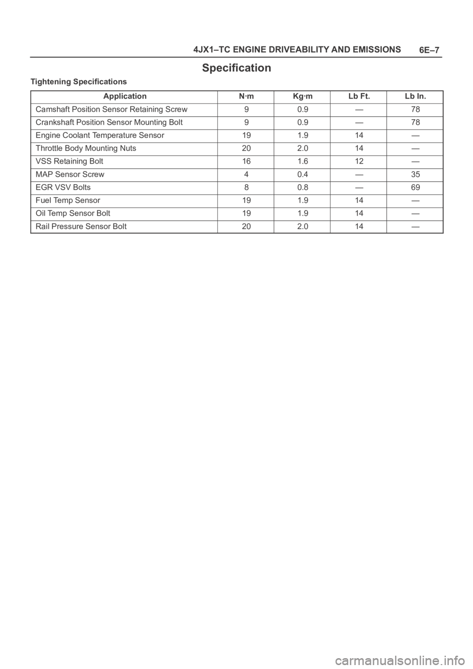
6E–7 4JX1–TC ENGINE DRIVEABILITY AND EMISSIONS
Specification
Tightening Specifications
Application
NꞏmKgꞏmLb Ft.Lb In.
Camshaft Position Sensor Retaining Screw90.9—78
Crankshaft Position Sensor Mounting Bolt90.9—78
Engine Coolant Temperature Sensor191.914—
Throttle Body Mounting Nuts202.014—
VSS Retaining Bolt161.612—
MAP Sensor Screw40.4—35
EGR VSV Bolts80.8—69
Fuel Temp Sensor191.914—
Oil Temp Sensor Bolt191.914—
Rail Pressure Sensor Bolt202.014—
Page 1910 of 6000
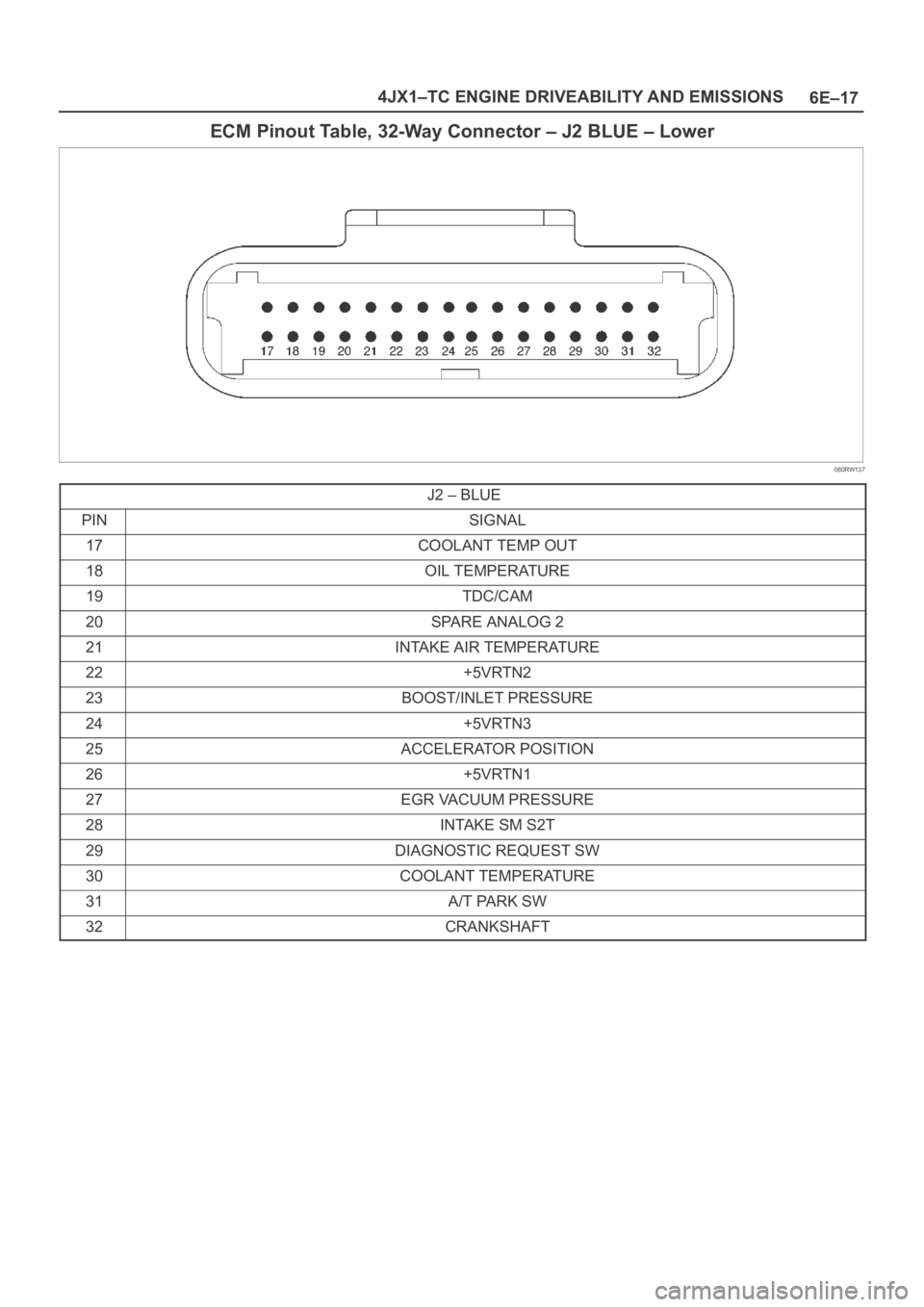
6E–17 4JX1–TC ENGINE DRIVEABILITY AND EMISSIONS
ECM Pinout Table, 32-Way Connector – J2 BLUE – Lower
060RW137
J2 – BLUE
PINSIGNAL
17COOLANT TEMP OUT
18OIL TEMPERATURE
19TDC/CAM
20SPARE ANALOG 2
21INTAKE AIR TEMPERATURE
22+5VRTN2
23BOOST/INLET PRESSURE
24+5VRTN3
25ACCELERATOR POSITION
26+5VRTN1
27EGR VACUUM PRESSURE
28INTAKE SM S2T
29DIAGNOSTIC REQUEST SW
30COOLANT TEMPERATURE
31A/T PARK SW
32CRANKSHAFT
Page 1912 of 6000
6E–19 4JX1–TC ENGINE DRIVEABILITY AND EMISSIONS
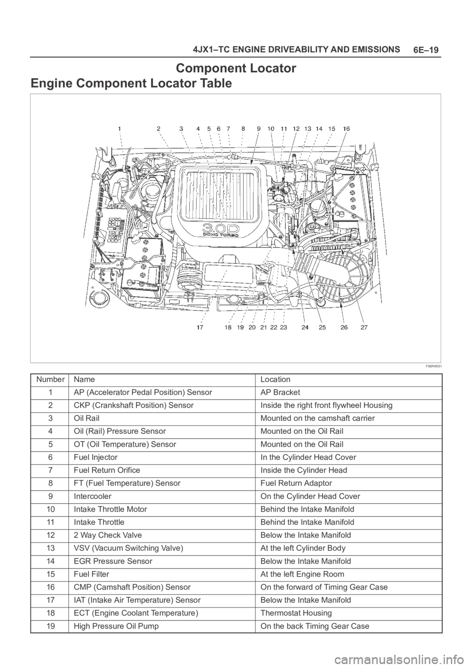
Component Locator
Engine Component Locator Table
F06RW051
NumberNameLocation
1AP (Accelerator Pedal Position) SensorAP Bracket
2CKP (Crankshaft Position) SensorInside the right front flywheel Housing
3Oil RailMounted on the camshaft carrier
4Oil (Rail) Pressure SensorMounted on the Oil Rail
5OT (Oil Temperature) SensorMounted on the Oil Rail
6Fuel InjectorIn the Cylinder Head Cover
7Fuel Return OrificeInside the Cylinder Head
8FT (Fuel Temperature) SensorFuel Return Adaptor
9IntercoolerOn the Cylinder Head Cover
10Intake Throttle MotorBehind the Intake Manifold
11Intake ThrottleBehind the Intake Manifold
122 Way Check ValveBelow the Intake Manifold
13VSV (Vacuum Switching Valve)At the left Cylinder Body
14EGR Pressure SensorBelow the Intake Manifold
15Fuel FilterAt the left Engine Room
16CMP (Camshaft Position) SensorOn the forward of Timing Gear Case
17IAT (Intake Air Temperature) SensorBelow the Intake Manifold
18ECT (Engine Coolant Temperature)Thermostat Housing
19High Pressure Oil PumpOn the back Timing Gear Case
Page 1916 of 6000
6E–23 4JX1–TC ENGINE DRIVEABILITY AND EMISSIONS
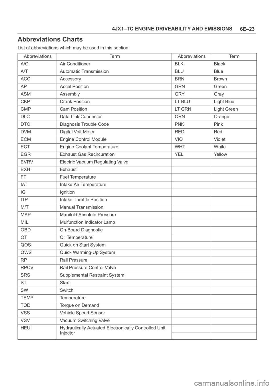
Abbreviations Charts
List of abbreviations which may be used in this section.
Abbreviations
Te r mAbbreviationsTe r m
A/CAir ConditionerBLKBlack
A/TAutomatic TransmissionBLUBlue
ACCAccessoryBRNBrown
APAccel PositionGRNGreen
ASMAssemblyGRYGray
CKPCrank PositionLT B L ULight Blue
CMPCam PositionLT G R NLight Green
DLCData Link ConnectorORNOrange
DTCDiagnosis Trouble CodePNKPink
DVMDigital Volt MeterREDRed
ECMEngine Control ModuleVIOViolet
ECTEngine Coolant TemperatureWHTWhite
EGRExhaust Gas RecircurationYELYe l l o w
EVRVElectric Vacuum Regulating Valve
EXHExhaust
FTFuel Temperature
IATIntake Air Temperature
IGIgnition
ITPIntake Throttle Position
M/TManual Transmission
MAPManifold Absolute Pressure
MILMulfunction Indicator Lamp
OBDOn-Board Diagnostic
OTOil Temperature
QOSQuick on Start System
QWSQuick Warming-Up System
RPRail Pressure
RPCVRail Pressure Control Valve
SRSSupplemental Restraint System
STStart
SWSwitch
TEMPTemperature
TODTorque on Demand
VSSVehicle Speed Sensor
VSVVacuum Switching Valve
HEUIHydraulically Actuated Electronically Controlled Unit
InjectorInjector