Page 2316 of 6000

TRANSMISSION CONTROL SYSTEM (4L30–E)7A1–71
DTC P1860 TCC Solenoid Electrical
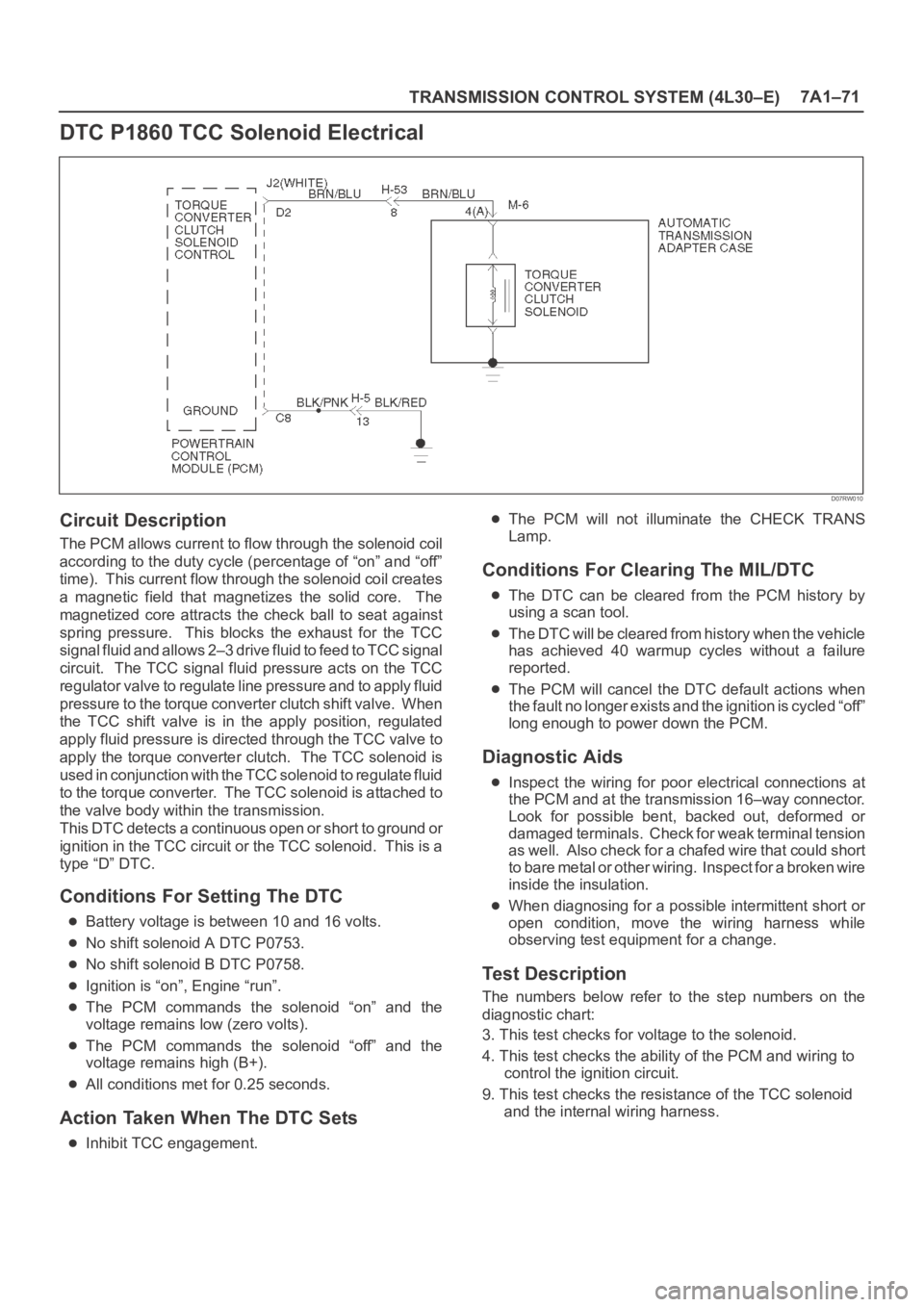
D07RW010
Circuit Description
The PCM allows current to flow through the solenoid coil
according to the duty cycle (percentage of “on” and “off”
time). This current flow through the solenoid coil creates
a magnetic field that magnetizes the solid core. The
magnetized core attracts the check ball to seat against
spring pressure. This blocks the exhaust for the TCC
signal fluid and allows 2–3 drive fluid to feed to TCC signal
circuit. The TCC signal fluid pressure acts on the TCC
regulator valve to regulate line pressure and to apply fluid
pressure to the torque converter clutch shift valve. When
the TCC shift valve is in the apply position, regulated
apply fluid pressure is directed through the TCC valve to
apply the torque converter clutch. The TCC solenoid is
used in conjunction with the TCC solenoid to regulate fluid
to the torque converter. The TCC solenoid is attached to
the valve body within the transmission.
This DTC detects a continuous open or short to ground or
ignition in the TCC circuit or the TCC solenoid. This is a
type “D” DTC.
Conditions For Setting The DTC
Battery voltage is between 10 and 16 volts.
No shift solenoid A DTC P0753.
No shift solenoid B DTC P0758.
Ignition is “on”, Engine “run”.
The PCM commands the solenoid “on” and the
voltage remains low (zero volts).
The PCM commands the solenoid “off” and the
voltage remains high (B+).
All conditions met for 0.25 seconds.
Action Taken When The DTC Sets
Inhibit TCC engagement.
The PCM will not illuminate the CHECK TRANS
Lamp.
Conditions For Clearing The MIL/DTC
The DTC can be cleared from the PCM history by
using a scan tool.
The DTC will be cleared from history when the vehicle
has achieved 40 warmup cycles without a failure
reported.
The PCM will cancel the DTC default actions when
the fault no longer exists and the ignition is cycled “off”
long enough to power down the PCM.
Diagnostic Aids
Inspect the wiring for poor electrical connections at
the PCM and at the transmission 16–way connector.
Look for possible bent, backed out, deformed or
damaged terminals. Check for weak terminal tension
as we ll. A lso ch eck fo r a ch af e d w ire th at cou l d s ho r t
to bare metal or other wiring. Inspect for a broken wire
inside the insulation.
When diagnosing for a possible intermittent short or
open condition, move the wiring harness while
observing test equipment for a change.
Test Description
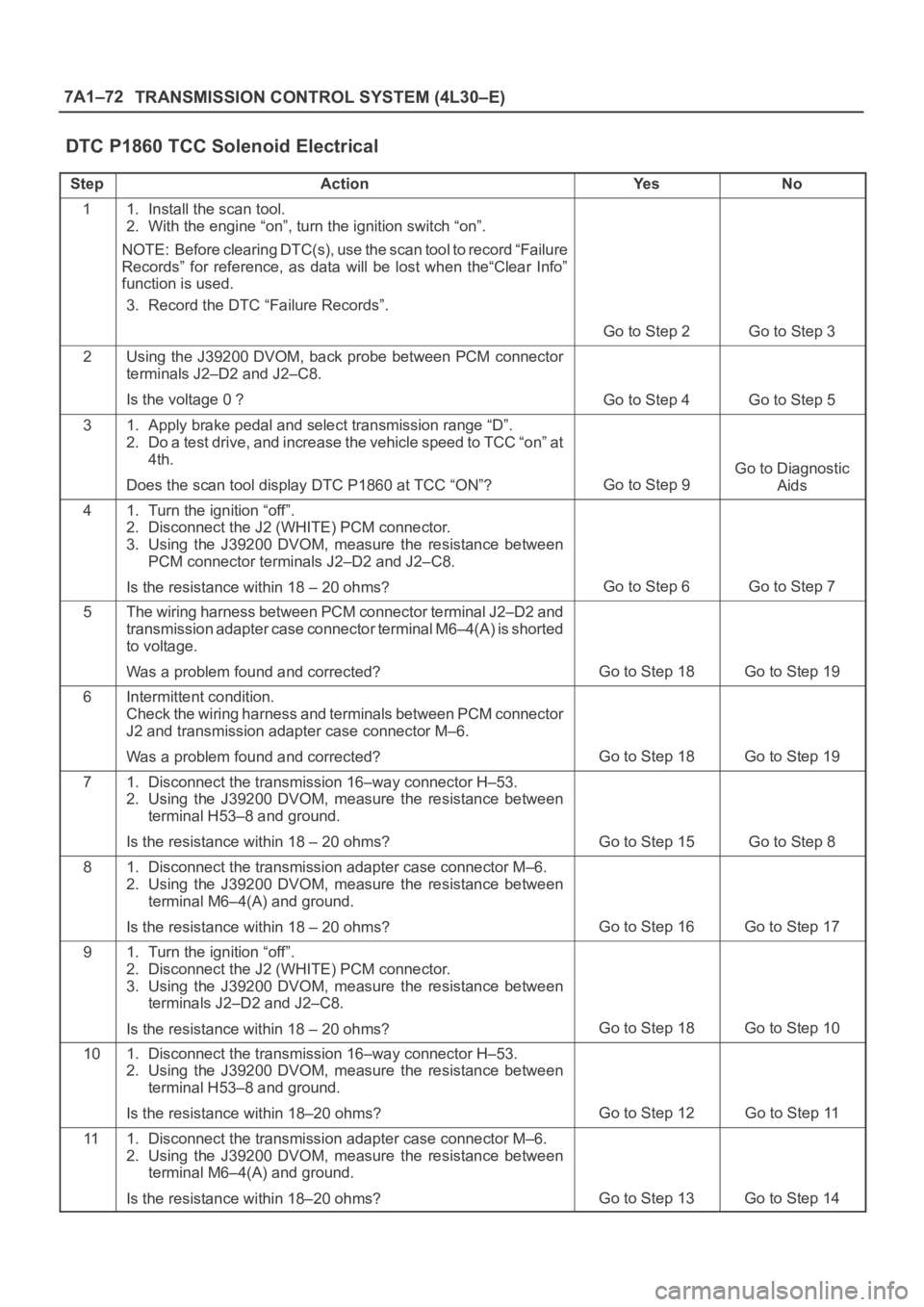
The numbers below refer to the step numbers on the
diagnostic chart:
3. This test checks for voltage to the solenoid.
4. This test checks the ability of the PCM and wiring to
control the ignition circuit.
9. This test checks the resistance of the TCC solenoid
and the internal wiring harness.
Page 2317 of 6000

7A1–72
TRANSMISSION CONTROL SYSTEM (4L30–E)
DTC P1860 TCC Solenoid Electrical
StepActionYe sNo
11. Install the scan tool.
2. With the engine “on”, turn the ignition switch “on”.
NOTE: Before clearing DTC(s), use the scan tool to record “Failure
Records” for reference, as data will be lost when the“Clear Info”
function is used.
3. Record the DTC “Failure Records”.
Go to Step 2Go to Step 3
2Using the J39200 DVOM, back probe between PCM connector
terminals J2–D2 and J2–C8.
Is the voltage 0 ?
Go to Step 4Go to Step 5
31. Apply brake pedal and select transmission range “D”.
2. Do a test drive, and increase the vehicle speed to TCC “on” at
4th.
Does the scan tool display DTC P1860 at TCC “ON”?
Go to Step 9
Go to Diagnostic
Aids
41. Turn the ignition “off”.
2. Disconnect the J2 (WHITE) PCM connector.
3. Using the J39200 DVOM, measure the resistance between
PCM connector terminals J2–D2 and J2–C8.
Is the resistance within 18 – 20 ohms?
Go to Step 6Go to Step 7
5The wiring harness between PCM connector terminal J2–D2 and
transmission adapter case connector terminal M6–4(A) is shorted
to voltage.
Was a problem found and corrected?
Go to Step 18Go to Step 19
6Intermittent condition.
Check the wiring harness and terminals between PCM connector
J2 and transmission adapter case connector M–6.
Was a problem found and corrected?
Go to Step 18Go to Step 19
71. Disconnect the transmission 16–way connector H–53.
2. Using the J39200 DVOM, measure the resistance between
terminal H53–8 and ground.
Is the resistance within 18 – 20 ohms?
Go to Step 15Go to Step 8
81. Disconnect the transmission adapter case connector M–6.
2. Using the J39200 DVOM, measure the resistance between
terminal M6–4(A) and ground.
Is the resistance within 18 – 20 ohms?
Go to Step 16Go to Step 17
91. Turn the ignition “off”.
2. Disconnect the J2 (WHITE) PCM connector.
3. Using the J39200 DVOM, measure the resistance between
terminals J2–D2 and J2–C8.
Is the resistance within 18 – 20 ohms?
Go to Step 18Go to Step 10
101. Disconnect the transmission 16–way connector H–53.
2. Using the J39200 DVOM, measure the resistance between
terminal H53–8 and ground.
Is the resistance within 18–20 ohms?
Go to Step 12Go to Step 11
111. Disconnect the transmission adapter case connector M–6.
2. Using the J39200 DVOM, measure the resistance between
terminal M6–4(A) and ground.
Is the resistance within 18–20 ohms?
Go to Step 13Go to Step 14
Page 2323 of 6000
MANUAL TRANSMISSION7B–5
Manual Transmission Assembly
Transmission and Associated Parts
220RW108
Legend
(1) Gear Control Lever and Knob
(2) Transfer Control Lever and Knob
(3) Front Console Assembly
(4) Grommet Assembly
(5) Transfer Protector
(6) Rear Propeller Shaft
(7) Front Propeller Shaft
(8) Exhaust Pipe
(9) Backup Lamp, 4WD Indicator, and 1–2
Indicator Switch Harness Connector
(10) Speedometer Sensor and 2WD–4WD Actuator
Harness Connector(11) Slave Cylinder Heat Protector
(12) Harness Heat Protector
(13) Slave Cylinder
(14) Dust Cover
(15) Engine Rear Mount Nut
(16) Engine Rear Mount Bolt
(17) Engine Rear Mount
(18) Third Crossmember
(19) Flywheel Under Cover
(20) Transmission Retaining Bolt
(21) Transmission Assembly with Transfer Case
Page 2324 of 6000
7B–6MANUAL TRANSMISSION
Removal
NOTE: Before remove the transmission and transfer
assembly from the vehicle, change the transfer mode to
2WD using push button on dash panel.
1. Remove engine hood.
2. Disconnect battery ground cable.
3. Remove the gear control lever knob.
4. Remove the front console assembly.
5. Remove the grommet assembly.
6. Remove the transmission control lever and transfer
control lever.
235RW014
7. Raise and support the vehicle with suitable jack
stand.
8. Remove transfer protector.
9. Remove the rear propeller shaft.
NOTE: Apply alignment marks on the flange at the both
front and rear side.
(4JX1)
401RW060
10. Remove the front propeller shaft.
NOTE: Apply alignment marks on the flange at both the
front and rear sides.
401RS003
11. Disconnect two oxygen sensor connectors from the
transmission harness (6VE1).
12.Remove the front and 3 way exhaust pipe (6VE1).
Remove the exhaust pipe with catalytic converter
(4JX1).
(4JX1)
150RW041
Page 2327 of 6000
MANUAL TRANSMISSION7B–9
16. Remove the slave cylinder heat protector.
17. Remove the harness heat protector (6VE1).
(6VE1)
225RW006
18. Remove two transmission harness clamps and
bracket (6VE1).
19. Remove the slave cylinder.
206RW002
20. Remove the two dust cover from transmission case.
21. Support the transfer case with a jack.22. Remove two engine rear mount nuts.
(6VE1)
022RT002
23. Remove third crossmember (6VE1).
24. Remove third crossmember with rear mount rubber
(4JX1).
(4JX1)
022RW013
25. Remove two engine rear mount bolts (6VE1).
26. Remove the rear mount from the transmission
(6VE1).
27. Remove three flywheel under cover (6VE1).
Page 2329 of 6000
MANUAL TRANSMISSION7B–11
220RW119
Legend
(1) Pressure Plate Assembly
(2) Release Bearing
(3) Wedge Collar
30. Remove the transmission retaining nuts and bolts.
31. Remove the transmission assembly with transfer
case from the vehicle.
NOTE: Remove the transfer case from the transmission
assembly if the transmission disassembly required.
Refer to Transfer Case in Drive Line/Axle section.
Installation
1. Apply a thin coat of molybdenum disulfide grease to
the top gear shaft spline.
2. Slowly operate the transmission jack until the front of
transmission is aligned with the rear of the engine.
The slope of the engine and the transmission must be
the same.
3. Align the top gear shaft spline with the clutch driven
plate spline.
220RS005
4. Install the transmission to the engine.
Tighten the transmission retaining nuts and bolts.
Page 2331 of 6000
MANUAL TRANSMISSION7B–13
(4JX1)
225RW020
5. Apply a force of about 113N (26 Ib) to the tip of the
shift fork in the direction of the transmission to engage
the clutch pressure plate and release bearing.
NOTE: A clicking sound is heard when the release
bearing and the tip of the diaphragm spring engage each
other.
Check to see if they are securely engaged by pushing the
tip of the shift fork toward the engine while applying a
force of about 25 N (5.5 lb). If the shift fork will not move,
then they are securely engaged.
220RS006
6. Install three flywheel under cover (6VE1).
Page 2332 of 6000

7B–14MANUAL TRANSMISSION
7. Install the engine rear mount to the transmission case
and tighten the fixing bolts specified torque (6VE1).
Torque: 41 Nꞏm (4.2kgꞏm/30 Ib ft)
8. Install the third crossmember to the frame and tighten
the fixing bolts specified torque.
Torque: 50 Nꞏm (5.1kgꞏm/37 Ib ft)
9. Tighten the engine rear mount nuts specified torque.
Torque: 50 Nꞏm (5.1kgꞏm/37 Ib ft)
10. Remove the transmission jack.
11. Apply the grease to top hole portion of the shift fork.
12. Install the slave cylinder and tighten the fixing bolts
specified torque.
Torque: 43 Nꞏm (4.4kgꞏm/32 Ib ft)
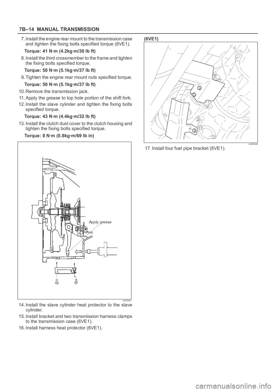
13. Install the clutch dust cover to the clutch housing and
tighten the fixing bolts specified torque.
Torque: 8 Nꞏm (0.8kgꞏm/69 Ib in)
220RS007
14. Install the slave cylinder heat protector to the slave
cylinder.
15. Install bracket and two transmission harness clamps
to the transmission case (6VE1).
16. Install harness heat protector (6VE1).(6VE1)
225RW006
17. Install four fuel pipe bracket (6VE1).