Page 2597 of 6000

The chassis electrical system is a 12–volt system with a
negative ground polarity.
Wire size are appropriate to respective circuits, and
classified by color. (The classification of harnesses by
color is shown on the circuit diagram for ease of harness
identification.)
The wire size is determined by load capacity and the
length of wire required.
The vehicle harnesses are: body harness, chassis
harness, engine room harness, instrument harness,
transmission harness, engine ECGI harness, dome light
harness, door harness, rear body harness, tailgate
harness, SRS harness and battery cables.
The harnesses are protected either by tape or corrugated
tube, depending on harness location.
The circuit for each system consists of the power source,
wire, fuse, relay, switch, load parts and ground, all of
which are shown on the circuit diagram.
In this section, each electrical device is classified by
system.
For major parts shown on the circuit based on the circuit
diagram for each system, a summary, diagnosis of
troubles and inspection procedures are detailed.
Notes for Working on Electrical
Items
Disconnecting the Battery Cable
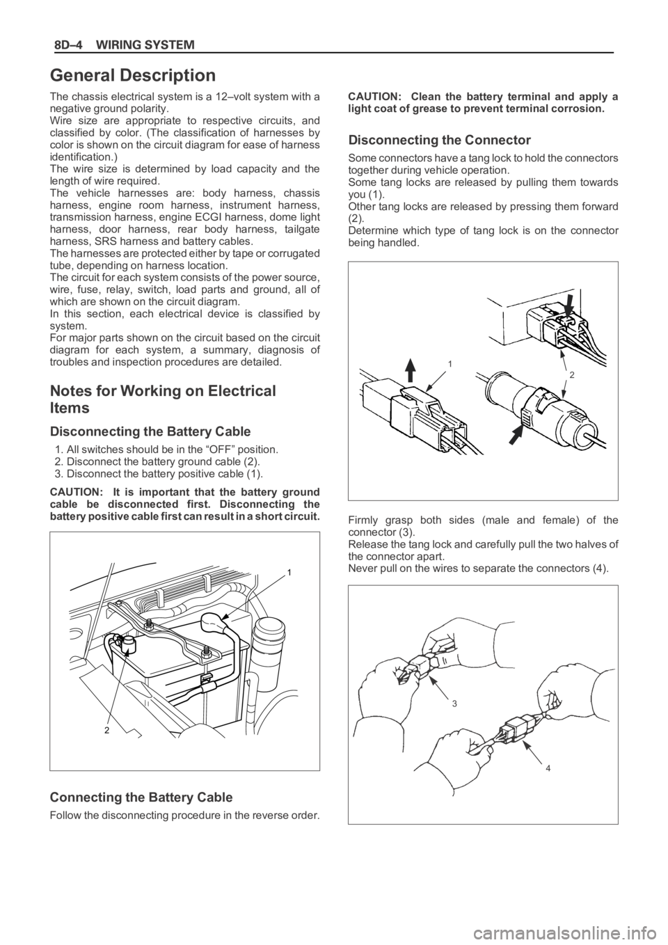
1. All switches should be in the “OFF” position.
2. Disconnect the battery ground cable (2).
3. Disconnect the battery positive cable (1).
CAUTION: It is important that the battery ground
cable be disconnected first. Disconnecting the
battery positive cable first can result in a short circuit.
Connecting the Battery Cable
Follow the disconnecting procedure in the reverse order.CAUTION: Clean the battery terminal and apply a
light coat of grease to prevent terminal corrosion.
Disconnecting the Connector
Some connectors have a tang lock to hold the connectors
together during vehicle operation.
Some tang locks are released by pulling them towards
you (1).
Other tang locks are released by pressing them forward
(2).
Determine which type of tang lock is on the connector
being handled.
Firmly grasp both sides (male and female) of the
connector (3).
Release the tang lock and carefully pull the two halves of
the connector apart.
Never pull on the wires to separate the connectors (4).
2
1
General Description
1
2
3
4
Page 2601 of 6000

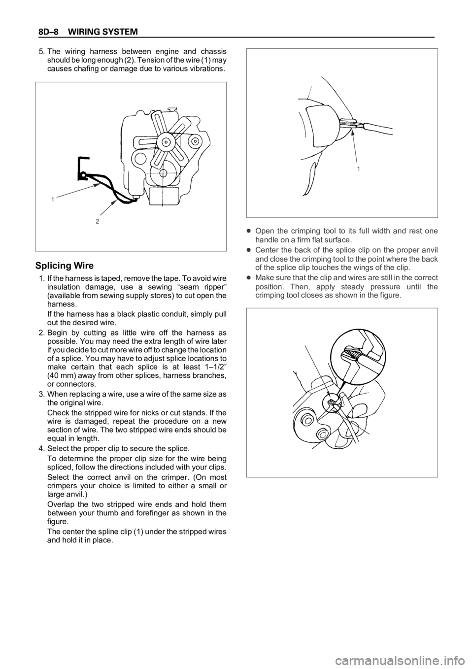
5. The wiring harness between engine and chassis
should be long enough (2). Tension of the wire (1) may
causes chafing or damage due to various vibrations.
Splicing Wire
1. If the harness is taped, remove the tape. To avoid wire
insulation damage, use a sewing “seam ripper”
(available from sewing supply stores) to cut open the
harness.
If the harness has a black plastic conduit, simply pull
out the desired wire.
2. Begin by cutting as little wire off the harness as
possible. You may need the extra length of wire later
if you decide to cut more wire off to change the location
of a splice. You may have to adjust splice locations to
make certain that each splice is at least 1–1/2”
(40 mm) away from other splices, harness branches,
or connectors.
3 . W h e n r e p l a c i n g a w i r e , u s e a w i r e o f t h e s a m e s i z e a s
the original wire.
Check the stripped wire for nicks or cut stands. If the
wire is damaged, repeat the procedure on a new
section of wire. The two stripped wire ends should be
equal in length.
4. Select the proper clip to secure the splice.
To determine the proper clip size for the wire being
spliced, follow the directions included with your clips.
Select the correct anvil on the crimper. (On most
crimpers your choice is limited to either a small or
large anvil.)
Overlap the two stripped wire ends and hold them
between your thumb and forefinger as shown in the
figure.
The center the spline clip (1) under the stripped wires
and hold it in place.
Open the crimping tool to its full width and rest one
handle on a firm flat surface.
Center the back of the splice clip on the proper anvil
and close the crimping tool to the point where the back
of the splice clip touches the wings of the clip.
Make sure that the clip and wires are still in the correct
position. Then, apply steady pressure until the
crimping tool closes as shown in the figure.
2
11
Page 2647 of 6000
3
P-2
H-142
2
B-11
P-10P-7
PCM
(A4)
CONDENSER
FANEHCU STARTER
(B)
STARTER
RELAY
(3)
P-6
BODY ENGINE FRAME
BATTERY
STARTER
SWRELAY & FUSE BOX
CONDENSER
FAN
RELAY
FL-2 50A
KEY SWFL-3 30A
PCMFL-4 30A
CONDENSER
FANFL-6 40A
ABS FL-1 80A
MAIN 8.0
B/R
8.0
B30.0
B8.0
B30.0
B/R
3.0
W/B
3.0
W/B
3.0
W/B
3.0
B/Y3.0
W/G3.0
B/R3.0
L/B2.0
W1.25
L/O
1.25
L3.0
W/G
3.0
W/B5.0
W
5.0
W
3.0
W/B
B-11IG1 ST IG2 ACC B1
7B-11
3B-11
5B-11
1
B2
OFF 4
B-11
P-5
P-1�+
�−
X-191
X-19
D08RWC56.
Page 2650 of 6000
3.0
B/Y3.0
B/Y
3.0
B/Y3.0
B/Y3.0
W/G3.0
B/R
3.0
B/R 3.0
B/Y
0.5
R/B
HAZARD
WARNING
SW
(8)PCM
MAIN
RELAY
(1)IGNITION
COILMETER STARTER
RELAY
(6)SEAT
HEATERWINDSHIELD
WIPER
MOTORRR
WIPER
MOTORHEADLIGHT
WIPER
MOTOR
AC GENERATOR
(IG) ALARM & RELAY
CONTROL UNIT C-3 10A
TURN
BACK
0.5
L/WC-4 10A
ELEC.
IGN.
0.5
L/YC-10 10A
METER
GAUGE
0.5
W/RC-1 10A
STARTER
RELAY
0.85
W/LC-5 15A
FRT WIPER
& WASHERC-6 10A
RR WIPER
& WASHERC-7 10A
H/LAMP
WIPER
FUSE BOX
1.25
B/OC-9 15A
IG COIL C-8 15A
ENGINE
0.5
L/B
0.85
B/Y
0.85
B/Y
0.5
R
0.75
B/R
SDM
(12)C-21 10A
SRS
1.25
G/RC-2 15A
SEAT
HEATER
H-631
3
H-63
��
D08RWB15
Page 2652 of 6000
P-2
H-142
2
B-11
P-10P-7
STARTER
RELAY
(4)
P-6
BODY ENGINE FRAME
BATTERY
STARTER
SWFUSE & RELAY BOX
FL-2 50A
KEY SW FL-1 80A
MAIN 8.0
B/R
8.0
B30.0
B8.0
B
3.0
W/B
3.0
W/B
3.0
W/B
3.0
B/Y3.0
W/G3.0
B/R3.0
L/B 3.0
W/B 3.0
W/B 30.0
B/R
B-11IG1 ST IG2 ACC B1
7
E
F
G
A
B-11
3
B
B-11
5
C
B-11
1
D
B2
OFF 4
B-11
STARTER
(B)
P-5
P-1+
−
X-112
4
X-11
ECM
(J3-1)
ECM
RELAY-1
FL-4 50A
ECM
3.0
R 3.0
W/B
X-102
4
X-10
ECM
(J3-2)
ECM
RELAY-2
3.0
R/W3.0
W/B
D08RWB17
Page 2653 of 6000
P-2
H-142
2
B-11
P-10P-7
STARTER
RELAY
(4)
P-6
BODY ENGINE FRAME
BATTERY
STARTER
SWFUSE & RELAY BOX
FL-2 50A
KEY SW FL-1 80A
MAIN 8.0
B/R
8.0
B30.0
B8.0
B
3.0
W/B
3.0
W/B
3.0
W/B
3.0
B/Y3.0
W/G3.0
B/R3.0
L/B 3.0
W/B 3.0
W/B 30.0
B/R
B-11IG1 ST IG2 ACC B1
7
E
F
G
A
B-11
3
B
B-11
5
C
B-11
1
D
B2
OFF 4
B-11
STARTER
(B)
P-5
P-1�+
�−
X-191
3
X-19
CONDENSER
FAN
CONDENSER
FAN
RELAY
FL-4 30A
CONDENSER
FAN
1.25
L 1.25
L/O
D08RWC54
Page 2658 of 6000
3.0
B/Y3.0
B/Y
3.0
B/Y3.0
B/Y3.0
W/G3.0
B/R
3.0
B/R 3.0
B/Y
0.5
R/B
HAZARD
WARNING
SW
(8)C-3 10A
TURN
BACK
0.5
L/WC-4 10A
ELEC.
IGN.
0.5
L/Y
METER ECM
(J2-9) ALARM & RELAY��
C O NTR O L UNITC-10 10A
METER
GAUGE
0.5
W/R
STARTER
RELAY
(6)C-1 10A
STARTER
RELAY
0.85
W/L
WINDSHIELD
WIPER
MOTORC-5 15A
FRT WIPER
& WASHERC-6 10A
RR WIPER
& WASHERC-7 10A
H/LAMP
WIPER
FUSE BOX
C-8 15A
ENGINE
0.5
L/B
RR
WIPER
MOTORHEADLIGHT
WIPER
MOTOR
0.85
B/Y
0.5
R
0.75
B/R
SDM
(12)C-21 10A
SRS
1.25
G/R
SEAT
HEATERC-2 15A
SEAT
HEATER
H-631
3
H-63
��
D08RWB20
Page 2661 of 6000
X-17M-25H-10H-12M-25 3.0
W/G
C-1 10A
STARTER RELAYFL-2 50A
KEY SWC-8 15A
ENGINE
MODE SW
(A/T)(M/T)
AC GENERATOR
STARTER
RELAY
STARTER SW
(ST)FL-1
PCM(C12)STARTER SW
(IG1)
STARTER SW(B2)
SHIFT LOCK
CONTROLLER(5)CHARGE
WARNING
LIGHT
(METER) FL-1
0.5
W/R
0.5
W/L
1.25
W/L
1.25
W/R
0.5
W/R0.5
W/R3.0
W/B
3.0
W/B
3.0
W/B
3.0
B/Y0.85
Y 0.5
W/R
0.85
W/G 0.85
W/G 0.85
W/G0.85
W/G0.75
W/G5.0
W 5.0
W
0.75
B/Y5.0
W 5.0
W
5.0
W
5.0
W 0.85
B/Y 0.85
B/Y3.0
B/Y
0.5
W/L
0.5
L2
15
1
4
32
10 11 423 3
2
1
1
10 1321 19 2
6
5 4
16
H-10H-42X-17
H-1X-17
H-13X-17
H-15P-8H-3
P-9
5.0
W
1
H-14
P-8H-3
X-17
H-16
H-3
H-2
H-2
H-15
H-14
P-8
A
B
C
D
X-17
IG
LB C
D08RW585