Page 4783 of 6000

6E–126
ENGINE DRIVEABILITY AND EMISSIONS
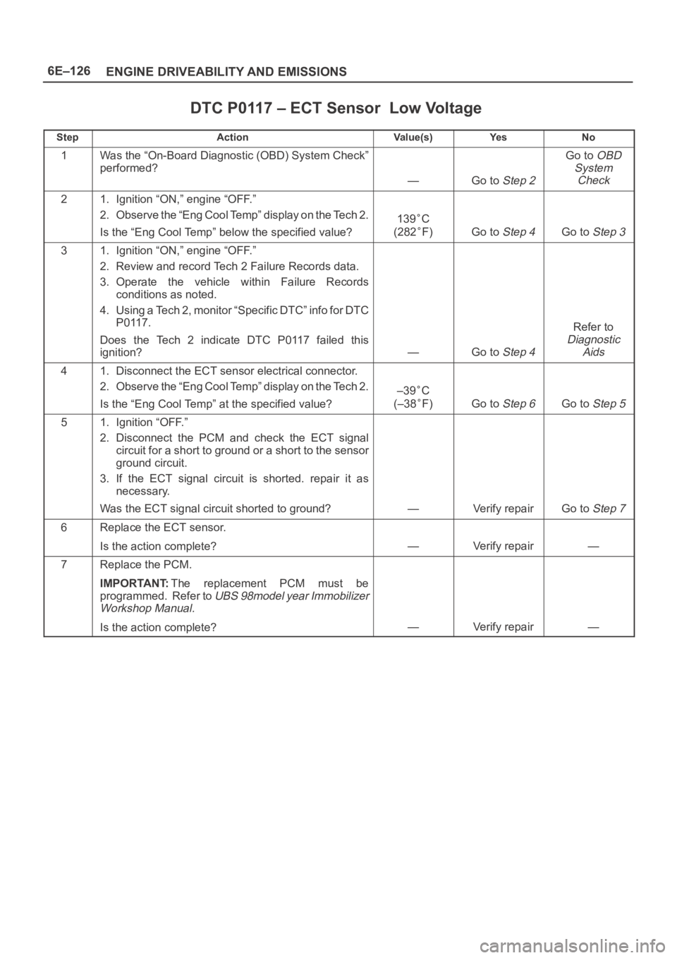
DTC P0117 – ECT Sensor Low Voltage
StepActionVa l u e ( s )Ye sNo
1Was the “On-Board Diagnostic (OBD) System Check”
performed?
—Go to Step 2
Go to OBD
System
Check
21. Ignition “ON,” engine “OFF.”
2. Observe the “Eng Cool Temp” display on the Tech 2.
Is the “Eng Cool Temp” below the specified value?
139C
(282
F)Go to Step 4Go to Step 3
31. Ignition “ON,” engine “OFF.”
2. Review and record Tech 2 Failure Records data.
3. Operate the vehicle within Failure Records
conditions as noted.
4. Using a Tech 2, monitor “Specific DTC” info for DTC
P0117.
Does the Tech 2 indicate DTC P0117 failed this
ignition?
—Go to Step 4
Refer to
Diagnostic
Aids
41. Disconnect the ECT sensor electrical connector.
2. Observe the “Eng Cool Temp” display on the Tech 2.
Is the “Eng Cool Temp” at the specified value?
–39C
(–38
F)Go to Step 6Go to Step 5
51. Ignition “OFF.”
2. Disconnect the PCM and check the ECT signal
circuit for a short to ground or a short to the sensor
ground circuit.
3. If the ECT signal circuit is shorted. repair it as
necessary.
Was the ECT signal circuit shorted to ground?
—Verify repairGo to Step 7
6Replace the ECT sensor.
Is the action complete?
—Verify repair—
7Replace the PCM.
IMPORTANT:The replacement PCM must be
programmed. Refer to
UBS 98model year Immobilizer
Workshop Manual.
Is the action complete?—Verify repair—
Page 4786 of 6000

6E–129 ENGINE DRIVEABILITY AND EMISSIONS
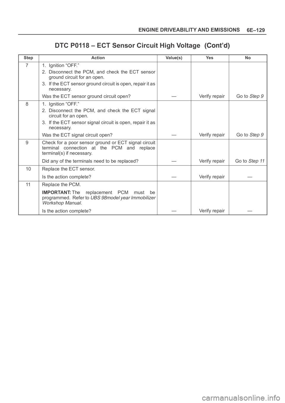
DTC P0118 – ECT Sensor Circuit High Voltage
StepNo Ye s Va l u e ( s ) Action
71. Ignition “OFF.”
2. Disconnect the PCM, and check the ECT sensor
ground circuit for an open.
3. If the ECT sensor ground circuit is open, repair it as
necessary.
Was the ECT sensor ground circuit open?
—Verify repairGo to Step 9
81. Ignition “OFF.”
2. Disconnect the PCM, and check the ECT signal
circuit for an open.
3. If the ECT sensor signal circuit is open, repair it as
necessary.
Was the ECT signal circuit open?
—Verify repairGo to Step 9
9Check for a poor sensor ground or ECT signal circuit
terminal connection at the PCM and replace
terminal(s) if necessary.
Did any of the terminals need to be replaced?
—Verify repairGo to Step 11
10Replace the ECT sensor.
Is the action complete?
—Verify repair—
11Replace the PCM.
IMPORTANT:The replacement PCM must be
programmed. Refer to
UBS 98model year Immobilizer
Workshop Manual.
Is the action complete?—Verify repair—
Page 4789 of 6000
6E–132
ENGINE DRIVEABILITY AND EMISSIONS
DTC P0121 –TP System Performance
StepNo Ye s Va l u e ( s ) Action
10Check the following items:
1. TP signal circuit or 5 volt reference “A” circuit for a
poor connection.
2. TP signal circuit or 5 volt reference “A” circuit for
high resistance between the PCM and the TP
sensor.
3. If a problem is found, repair wiring harness as
necessary.
Was a problem found?
—Verify repairGo to Step 12
11Replace the TP sensor.
Is the action complete?
—Verify repair—
12Replace the PCM.
IMPORTANT:The replacement PCM must be
programmed. Refer to
UBS 98model year Immobilizer
Workshop Manual.
Is the action complete?—Verify repair—
Page 4792 of 6000
6E–135 ENGINE DRIVEABILITY AND EMISSIONS
DTC P0122 –TP Sensor Circuit Low Voltage
StepNo Ye s Va l u e ( s ) Action
10Check the TP sensor signal circuit for a poor
connection at the TP sensor and replace the terminal if
necessary.
Did the terminal require replacement?
—Verify repairGo to Step 11
11Replace the TP sensor.
Is the action complete?
—Verify repair—
12Replace the PCM.
IMPORTANT:The replacement PCM must be
programmed. Refer to
UBS 98model year Immobilizer
Workshop Manual.
Is the action complete?—Verify repair—
Page 4795 of 6000
6E–138
ENGINE DRIVEABILITY AND EMISSIONS
DTC P0123 – TP Sensor Circuit High Voltage
StepNo Ye s Va l u e ( s ) Action
101. Ignition “OFF.”
2. Disconnect the PCM, and check for an open sensor
ground circuit to the TP sensor.
3. If a problem is found, repair it as necessary.
Was the sensor ground circuit to the TP sensor open?
—Verify repairGo to Step 12
11Replace the TP sensor.
Is the action complete?
—Verify repair—
12Replace the PCM.
IMPORTANT:The replacement PCM must be
programmed. Refer to
UBS 98model year Immobilizer
Workshop Manual.
Is the action complete?—Verify repair—
Page 4798 of 6000
6E–141 ENGINE DRIVEABILITY AND EMISSIONS
DTC P0131 –HO2S Circuit Low Voltage Bank 1 Sensor 1
StepNo Ye s Va l u e ( s ) Action
81. Ignition “OFF.”
2. Reconnect the PCM, leave the sensor
disconnected.
3. Ignition “ON.”
Does the Tech 2 indicate Bank 1 HO2S 1 voltage
between the specified values?
425-475 mV
Refer to
Diagnostic
Aids
Go to Step 9
9Replace the PCM.
IMPORTANT:The replacement PCM must be
programmed. Refer to
UBS 98model year Immobilizer
Workshop Manual.
Is the action complete?—Verify repair—
Page 4801 of 6000
6E–144
ENGINE DRIVEABILITY AND EMISSIONS
DTC P0132 – HO2S Circuit High Voltage Bank 1 Sensor 1
StepNo Ye s Va l u e ( s ) Action
61. Ignition “ON,” engine“OFF.”
2. At Bank 1 HO2S 1 connector (PCM side) jumper
both the HO2S high and low signal circuits (PCM
side) to ground.
3. Using a Tech 2, monitor Bank 1 HO2S 1 voltage.
Is Bank 1 HO2S 1 voltage below the specified value?
10 mVGo to Step 7Go to Step 8
71. Disconnect the jumpers to ground from Bank 1
HO2S 1 PCM-side connector.
2. With the HO2S 1 connector disconnected, monitor
Bank 1 HO2S 1 voltage.
Is Bank 1 HO2S 1 voltage between the specified
values?
425-475 mV
Refer to
Diagnostic
Aids
Go to Step 8
8Replace the PCM.
IMPORTANT:The replacement PCM must be
programmed. Refer to
UBS 98model year Immobilizer
Workshop Manual.
Is the action complete?—Verify repair—
Page 4804 of 6000
6E–147 ENGINE DRIVEABILITY AND EMISSIONS
DTC P0134 –HO2S Circuit Insufficient Activity Bank 1 Sensor 1
StepNo Ye s Va l u e ( s ) Action
81. Ignition “OFF.”
2. With the PCM disconnected, check continuity of the
Bank 1 HO2S 1 low circuit.
3. If the Bank 1 HO2S 1 low circuit measures over 5
ohms, repair open or poor connection as necessary.
Was a Bank 1 HO2S 1 low circuit problem found and
corrected?
—Verify repairGo to Step 9
91. Ignition “ON,” engine “OFF.”
2. Disconnect Bank 1 HO2S 1 and jumper the HO2S
high and low circuits (PCM side) to ground.
3. Using Tech 2, monitor Bank 1 HO2S 1 voltage.
Is Bank 1 HO2S 1 voltage in the specified range?
0-10 mVGo to Step 10Go to Step 11
10Replace Bank 1 HO2S 1.
Is the action complete?
—Verify repair—
11Replace the PCM.
IMPORTANT:The replacement PCM must be
programmed. Refer to
UBS 98model year Immobilizer
Workshop Manual.
Is the action complete?—Verify repair—