1998 OPEL FRONTERA ESP
[x] Cancel search: ESPPage 3366 of 6000
SECURITY AND LOCKS8H–27
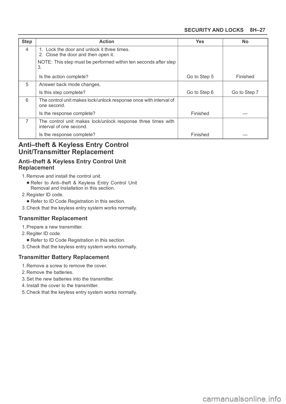
StepNo Ye s Action
41. Lock the door and unlock it three times.
2. Close the door and then open it.
NOTE: This step must be performed within ten seconds after step
3.
Is the action complete?
Go to Step 5Finished
5Answer back mode changes.
Is this step complete?
Go to Step 6Go to Step 7
6The control unit makes lock/unlock response once with interval of
one second.
Is the response complete?
Finished—
7The control unit makes lock/unlock response three times with
interval of one second.
Is the response complete?
Finished—
Anti–theft & Keyless Entry Control
Unit/Transmitter Replacement
Anti–theft & Keyless Entry Control Unit
Replacement
1. Remove and install the control unit.
Refer to Anti–theft & Keyless Entry Control Unit
Removal and Installation in this section.
2. Register ID code.
Refer to ID Code Registration in this section.
3. Check that the keyless entry system works normally.
Transmitter Replacement
1. Prepare a new transmitter.
2. Regiter ID code.
Refer to ID Code Registration in this section.
3. Check that the keyless entry system works normally.
Transmitter Battery Replacement
1. Remove a screw to remove the cover.
2. Remove the batteries.
3. Set the new batteries into the transmitter.
4. Install the cover to the transmitter.
5. Check that the keyless entry system works normally.
Page 3491 of 6000
RESTRAINT CONTROL SYSTEM 9J1–4
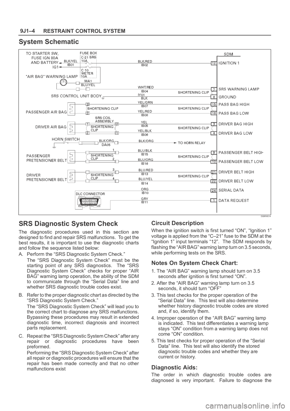
System Schematic
D09RW014
SRS Diagnostic System Check
The diagnostic procedures used in this section are
designed to find and repair SRS malfunctions. To get the
best results, it is important to use the diagnostic charts
and follow the sequence listed below:
A. Perform the “SRS Diagnostic System Check.”
The “SRS Diagnostic System Check” must be the
starting point of any SRS diagnostics. The “SRS
Diagnostic System Check” checks for proper “AIR
BAG” warning lamp operation, the ability of the SDM
to communicate through the “Serial Data” line and
whether SRS diagnostic trouble codes exist.
B. Refer to the proper diagnostic chart as directed by the
“SRS Diagnostic System Check.”
The “SRS Diagnostic System Check” will lead you to
the correct chart to diagnose any SRS malfunctions.
Bypassing these procedures may result in extended
diagnostic time, incorrect diagnosis and incorrect
parts replacement.
C. Repeat the “SRS Diagnostic System Check” after any
repair or diagnostic procedures have been
preformed.
Performing the “SRS Diagnostic System Check” after
all repair or diagnostic procedures will ensure that the
repair has been made correctly and that no other
malfunctions exist
Circuit Description
When the ignition switch is first turned “ON”, “Ignition 1”
voltage is applied from the “C–21” fuse to the SDM at the
“Ignition 1” input terminals “12”. The SDM responds by
flashing the “AIR BAG” warning lamp turn on 3.5 seconds,
while performing tests on the SRS.
Notes On System Check Chart:
1. The “AIR BAG” warning lamp should turn on 3.5
seconds after ignition is first turned “ON”.
2. After the “AIR BAG” warning lamp turn on 3.5
seconds, it should turn “OFF”
3. This test checks for the proper operation of the
“Serial Data” line. This test will also determine
whether history diagnostic trouble codes are stored
and, if so, identify them.
4. Improper operation of the “AIR BAG” warning lamp
is indicated. This test differentiates a warning lamp
stays “ON” condition from a warning lamp does not
come “ON” condition.
5. This test checks for proper operation of the “Serial
Data” line. This test will also identify the stored
diagnostic trouble codes and whether they are
current or history.
Diagnostic Aids:
The order in which diagnostic trouble codes are
diagnosed is very important. Failure to diagnose the
Page 3495 of 6000
RESTRAINT CONTROL SYSTEM 9J1–8
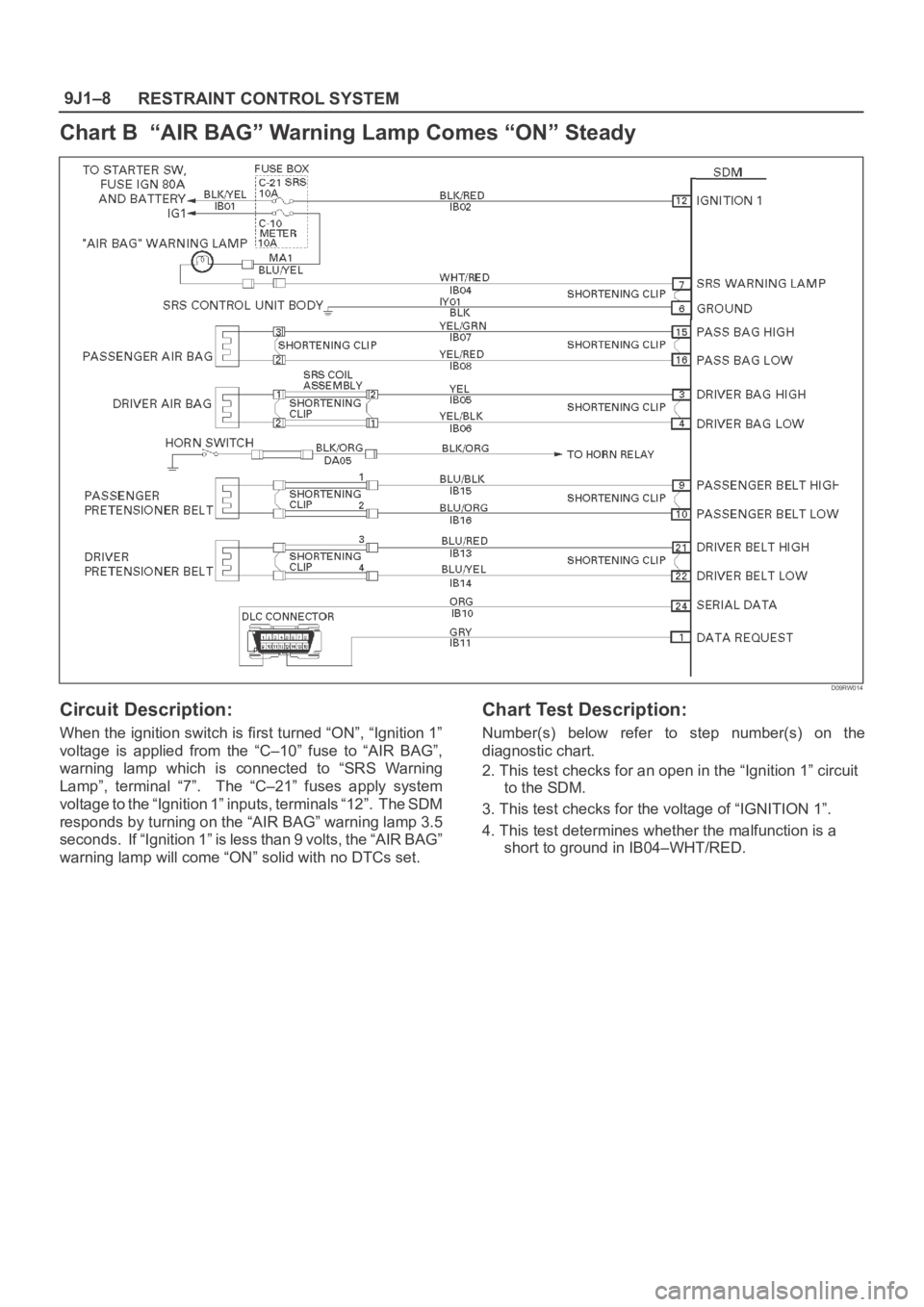
Chart B “AIR BAG” Warning Lamp Comes “ON” Steady
D09RW014
Circuit Description:
When the ignition switch is first turned “ON”, “Ignition 1”
voltage is applied from the “C–10” fuse to “AIR BAG”,
warning lamp which is connected to “SRS Warning
Lamp”, terminal “7”. The “C–21” fuses apply system
voltage to the “Ignition 1” inputs, terminals “12”. The SDM
responds by turning on the “AIR BAG” warning lamp 3.5
seconds. If “Ignition 1” is less than 9 volts, the “AIR BAG”
warning lamp will come “ON” solid with no DTCs set.
Chart Test Description:
Number(s) below refer to step number(s) on the
diagnostic chart.
2. This test checks for an open in the “Ignition 1” circuit
to the SDM.
3. This test checks for the voltage of “IGNITION 1”.
4. This test determines whether the malfunction is a
short to ground in IB04–WHT/RED.
Page 3497 of 6000
RESTRAINT CONTROL SYSTEM 9J1–10
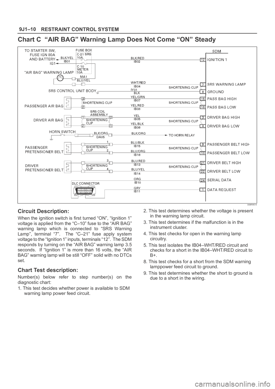
Chart C “AIR BAG” Warning Lamp Does Not Come “ON” Steady
D09RW014
Circuit Description:
When the ignition switch is first turned “ON”, “Ignition 1”
voltage is applied from the “C–10” fuse to the “AIR BAG”
warning lamp which is connected to “SRS Warning
Lamp”, terminal “7”. The “C–21” fuse apply system
voltage to the “Ignition 1” inputs, terminals “12”. The SDM
responds by turning on the “AIR BAG” warning lamp 3.5
seconds. If “Ignition 1” is more than 16 volts, the “AIR
BAG” warning lamp will be still “OFF” solid with no DTCs
set.
Chart Test description:
Number(s) below refer to step number(s) on the
diagnostic chart:
1. This test decides whether power is available to SDM
warning lamp power feed circuit.2. This test determines whether the voltage is present
in the warning lamp circuit.
3. This test determines if the malfunction is in the
instrument cluster.
4. This test checks for open in the warning lamp
circuitry.
5. This test isolates the IB04–WHT/RED circuit and
checks for a short in the IB04–WHT/RED circuit to
B+.
8. This test checks for a short from the SDM warning
lamppower feed circuit to ground.
9. This test determines whether the short to ground is
due to a short in the wiring.
Page 3500 of 6000
9J1–13
RESTRAINT CONTROL SYSTEM
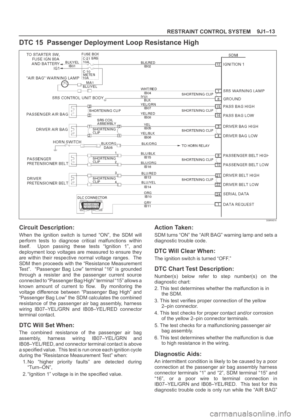
DTC 15 Passenger Deployment Loop Resistance High
D09RW014
Circuit Description:
When the ignition switch is turned “ON”, the SDM will
perform tests to diagnose critical malfunctions within
itself. Upon passing these tests “Ignition 1”, and
deployment loop voltages are measured to ensure they
are within their respective normal voltage ranges. The
SDM then proceeds with the “Resistance Measurement
Test”. “Passenger Bag Low” terminal “16” is grounded
through a resister and the passenger current source
connected to “Passenger Bag High” terminal “15” allows a
known amount of current to flow. By monitoring the
voltage difference between “Passenger Bag High” and
“Passenger Bag Low” the SDM calculates the combined
resistance of the passenger air bag assembly, harness
wiring IB07–YEL/GRN and IB08–YEL/RED connector
terminal contact.
DTC Will Set When:
The combined resistance of the passenger air bag
assembly, harness wiring IB07–YEL/GRN and
IB08–YEL/RED, and connector terminal contact is above
a specified value. This test is run once each ignition cycle
during the “Resistance Measurement Test” when:
1. No “higher priority faults” are detected during
“Turn–ON”,
2. “Ignition 1” voltage is in the specified value.
Action Taken:
SDM turns “ON” the “AIR BAG” warning lamp and sets a
diagnostic trouble code.
DTC Will Clear When:
The ignition switch is turned “OFF.”
DTC Chart Test Description:
Number(s) below refer to step number(s) on the
diagnostic chart:
2. This test determines whether the malfunction is in
the SDM.
3. This test verifies proper connection of the yellow
2–pin connector.
4. This test checks for proper contact and/or corrosion
of the yellow 2–pin connector terminals.
5. The test checks for a malfunctioning passenger air
bag assembly.
6. This test determines whether the malfunction is due
to high resistance in the wiring.
Diagnostic Aids:
An intermittent condition is likely to be caused by a poor
connection at the passenger air bag assembly harness
connector terminals “1” and “2”, SDM terminal “15” and
“16”, or a poor wire to terminal connection in
IB07–YEL/GRN and IB08–YEL/RED. This test for this
diagnostic trouble code is only run while the “AIR BAG”
Page 3502 of 6000
9J1–15
RESTRAINT CONTROL SYSTEM
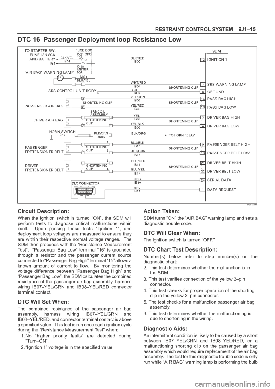
DTC 16 Passenger Deployment loop Resistance Low
D09RW014
Circuit Description:
When the ignition switch is turned “ON”, the SDM will
perform tests to diagnose critical malfunctions within
itself. Upon passing these tests “Ignition 1”, and
deployment loop voltages are measured to ensure they
are within their respective normal voltage ranges. The
SDM then proceeds with the “Resistance Measurement
Test”. “Passenger Bag Low” terminal “16” is grounded
through a resistor and the passenger current source
connected to “Passenger Bag High” terminal “15” allows a
known amount of current to flow. By monitoring the
voltage difference between “Passenger Bag High” and
“Passenger Bag Low”, the SDM calculates the combined
resistance of the passenger air bag assembly, harness
wiring IB07–YEL/GRN and IB08–YEL/RED connector
terminal contact.
DTC Will Set When:
The combined resistance of the passenger air bag
assembly, harness wiring IB07–YEL/GRN and
IB08–YEL/RED, and connector terminal contact is above
a specified value. This test is run once each ignition cycle
during the “Resistance Measurement Test” when:
1. No “higher priority faults” are detected during
“Turn–ON”,
2. “Ignition 1” voltage is in the specified value.
Action Taken:
SDM turns “ON” the “AIR BAG” warning lamp and sets a
diagnostic trouble code.
DTC Will Clear When:
The ignition switch is turned “OFF.”
DTC Chart Test Description:
Number(s) below refer to step number(s) on the
diagnostic chart:
2. This test determines whether the malfunction is in
the SDM.
3. This test verifies connection of the yellow 2–pin
connector.
4. This test cheeks for proper operation of the shorting
clip in the yellow 2–pin connector.
5. The test checks for a malfunction passenger air bag
assembly.
6. This test determines whether the malfunctioning is
due to shortening in the wiring.
Diagnostic Aids:
An intermittent condition is likely to be caused by a short
between IB07–YEL/GRN and IB08–YEL/RED, or a
malfunctioning shorting clip on the passenger air bag
assembly which would require replacement of the air bag
assembly. The test for this diagnostic trouble code is only
run while “AIR BAG” warning lamp is performing the bulb
Page 3504 of 6000
9J1–17
RESTRAINT CONTROL SYSTEM
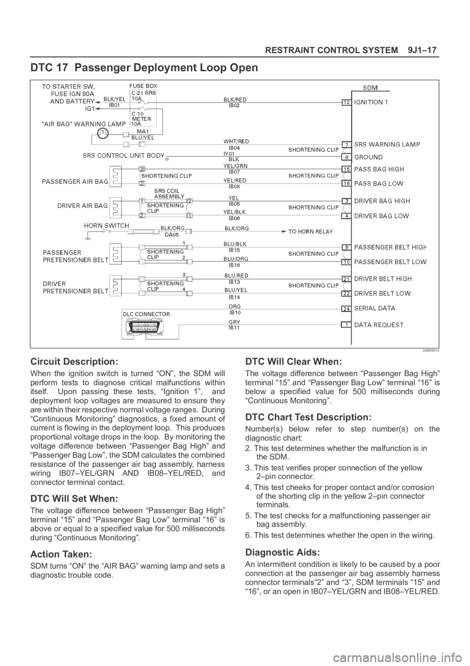
DTC 17 Passenger Deployment Loop Open
D09RW014
Circuit Description:
When the ignition switch is turned “ON”, the SDM will
perform tests to diagnose critical malfunctions within
itself. Upon passing these tests, “Ignition 1”, and
deployment loop voltages are measured to ensure they
are within their respective normal voltage ranges. During
“Continuous Monitoring” diagnostics, a fixed amount of
current is flowing in the deployment loop. This produces
proportional voltage drops in the loop. By monitoring the
voltage difference between “Passenger Bag High” and
“Passenger Bag Low”, the SDM calculates the combined
resistance of the passenger air bag assembly, harness
wiring IB07–YEL/GRN AND IB08–YEL/RED, and
connector terminal contact.
DTC Will Set When:
The voltage difference between “Passenger Bag High”
terminal “15” and “Passenger Bag Low” terminal “16” is
above or equal to a specified value for 500 milliseconds
during “Continuous Monitoring”.
Action Taken:
SDM turns “ON” the “AIR BAG” warning lamp and sets a
diagnostic trouble code.
DTC Will Clear When:
The voltage difference between “Passenger Bag High”
terminal “15” and “Passenger Bag Low” terminal “16” is
below a specified value for 500 milliseconds during
“Continuous Monitoring”.
DTC Chart Test Description:
Number(s) below refer to step number(s) on the
diagnostic chart:
2. This test determines whether the malfunction is in
the SDM.
3. This test verifies proper connection of the yellow
2–pin connector.
4. This test cheeks for proper contact and/or corrosion
of the shorting clip in the yellow 2–pin connector
terminals.
5. The test checks for a malfunctioning passenger air
bag assembly.
6. This test determines whether the open in the wiring.
Diagnostic Aids:
An intermittent condition is likely to be caused by a poor
connection at the passenger air bag assembly harness
connector terminals“2” and “3”, SDM terminals “15” and
“16”, or an open in IB07–YEL/GRN and IB08–YEL/RED.
Page 3506 of 6000
9J1–19
RESTRAINT CONTROL SYSTEM
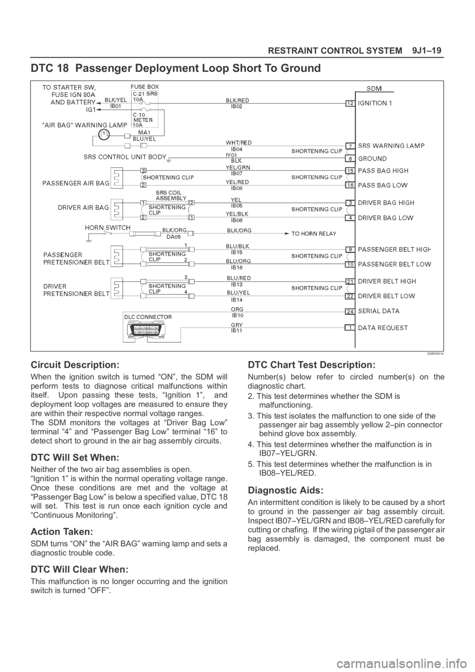
DTC 18 Passenger Deployment Loop Short To Ground
D09RW014
Circuit Description:
When the ignition switch is turned “ON”, the SDM will
perform tests to diagnose critical malfunctions within
itself. Upon passing these tests, “Ignition 1”, and
deployment loop voltages are measured to ensure they
are within their respective normal voltage ranges.
The SDM monitors the voltages at “Driver Bag Low”
terminal “4” and “Passenger Bag Low” terminal “16” to
detect short to ground in the air bag assembly circuits.
DTC Will Set When:
Neither of the two air bag assemblies is open.
“Ignition 1” is within the normal operating voltage range.
Once these conditions are met and the voltage at
“Passenger Bag Low” is below a specified value, DTC 18
will set. This test is run once each ignition cycle and
“Continuous Monitoring”.
Action Taken:
SDM turns “ON” the “AIR BAG” warning lamp and sets a
diagnostic trouble code.
DTC Will Clear When:
This malfunction is no longer occurring and the ignition
switch is turned “OFF”.
DTC Chart Test Description:
Number(s) below refer to circled number(s) on the
diagnostic chart.
2. This test determines whether the SDM is
malfunctioning.
3. This test isolates the malfunction to one side of the
passenger air bag assembly yellow 2–pin connector
behind glove box assembly.
4. This test determines whether the malfunction is in
IB07–YEL/GRN.
5. This test determines whether the malfunction is in
IB08–YEL/RED.
Diagnostic Aids:
An intermittent condition is likely to be caused by a short
to ground in the passenger air bag assembly circuit.
Inspect IB07–YEL/GRN and IB08–YEL/RED carefully for
cutting or chafing. If the wiring pigtail of the passenger air
bag assembly is damaged, the component must be
replaced.